Towards indoor navigation for a multimedia platform H.C. van den Boogaard Thesis for obtaining the Master of Science degree in Computer Science from the University of Twente, Enschede, The Netherlands
Graduation Committee: dr. ir. M.J. van Sinderen dr. ir. L. Ferreira Pires ing. F.D.P. Polman
Enschede, The Netherlands November 2007
Abstract The Guide ID Multimedia platform can brighten the life of a museum visitor by enhancing the experience with a complete multimedia tour though the museum. The current version of this platform however does only give the visitor background information about the exhibits in the museum. In some museums however the collection and/or the museum itself is so large that a multimedia tour can only contain some of the most important exhibits in the collection. In those museums it would be likely if the platform can also assist the visitor and lead him on his way from exhibit to exhibit, in a way a car route planner would do so. For this the platform needs a more or less exact location of the visitor during his visit. For outdoor area's one could use the Global Positioning System (GPS) but this does not work in an indoor environment. Much research is going on in the field of indoor positioning and indoor navigation. Many solution exist but they all have their own advantages and disadvantages. There seems to be no 'holy grail' as an indoor solution if it comes to positioning. Besides that the Guide ID company and its platform have very specific needs if it comes to positioning in a museological environment. In this thesis the existing techniques for indoor positioning are investigated and evaluated for use in the Guide ID platform, concluding that existing techniques would not optimally fit to the needs of Guide ID and its platform. The second part of the thesis therefore proposes a custom made indoor positioning system that suits the requirements of Guide ID best. It is mainly based on techniques that a (active) RFID positioning system would have but it addresses some drawbacks and includes a lot more flexibility than when standard RFID components are used. The hardware needed for the system was carefully selected and integrated to a circuit board with which some prototype devices could be made. The prototypes are used to create an initial indoor positioning and navigation system. This proof of concept shows the added value when integrated to the Guide ID platform.
i
Table of Contents 1
Introduction...........................................................................................1 1.1 1.2 1.3 1.4
2
Motivation...............................................................................................1 Objectives...............................................................................................1 Approach................................................................................................2 Structure................................................................................................2
Background and basic principles of positioning and navigation...........4 2.1 What is a position...................................................................................4 2.2 The difference between positioning and navigation...............................5 2.3 Short historical background....................................................................5 2.4 The modern approach............................................................................6 2.5 Major advantages and disadvantages of radio based positioning systems..........................................................................................................6 2.6 Classification of radio positioning techniques........................................7 2.6.1 2.6.2 2.6.3 2.6.4 2.6.5
Cell of Origin..........................................................................................7 Received Signal Strength Indication.......................................................8 Time of Arrival........................................................................................8 Time Difference of Arrival......................................................................8 Angle Of Arrival......................................................................................9
2.7 Basic mathematical background............................................................9
3
Analysis of available technologies......................................................11 3.1 Available technologies..........................................................................11 3.1.1 3.1.2 3.1.3 3.1.4 3.1.5 3.1.6 3.1.7
Infrared................................................................................................11 Bluetooth..............................................................................................11 Global Positioning System....................................................................13 RFID......................................................................................................14 Ultra Wideband....................................................................................15 Ultrasound............................................................................................16 Wireless LAN........................................................................................16
3.2 General requirements...........................................................................17 3.3 Evaluation of available technologies against the Guide ID requirements 18 3.4 General conclusion...............................................................................20
4
System design and architecture.........................................................21 4.1 4.2 4.3 4.4
Specific requirements...........................................................................21 Scenario................................................................................................21 Definition of system components.........................................................23 Architecture..........................................................................................24 4.4.1 Overview..............................................................................................24 4.4.2 Beacon architecture.............................................................................24 4.4.3 Receiver architecture...........................................................................25
ii
4.5 System behavior...................................................................................25 4.5.1 4.5.2 4.5.3 4.5.4 4.5.5 4.5.6
5
Overview..............................................................................................26 Normal beacon behavior......................................................................26 Normal receiver behavior.....................................................................28 Handheld to receiver communication..................................................28 Requesting configuration.....................................................................29 Configuration itself...............................................................................30
System implementation......................................................................32 5.1 Hardware implementation....................................................................32 5.1.1 5.1.2 5.1.3 5.1.4 5.1.5 5.1.6
CC1100 Transceiver chip......................................................................32 MSP430F2013 microcontroller..............................................................33 Saft Lithium battery.............................................................................34 SP3232 Serial linedriver.......................................................................34 OXCF950..............................................................................................35 Antenna design....................................................................................35
5.2 Radio communication...........................................................................35 5.2.1 5.2.2 5.2.3 5.2.4
Basic radio communication parameters...............................................35 Transceiver low level packet handling.................................................37 Transceiver high level packet handling................................................37 State machines....................................................................................39
5.3 RSSI filter..............................................................................................40
6
Evaluation and results........................................................................43 6.1 6.2 6.3 6.4
Evaluation of the system......................................................................43 Filter.....................................................................................................48 Evaluation of power use.......................................................................53 Evaluation of requirements against the proposed system...................56 6.4.1 6.4.2 6.4.3 6.4.4
7
Costs....................................................................................................56 Maintenance.........................................................................................57 Usability and scalability........................................................................57 Infrastructure.......................................................................................57
Conclusions.........................................................................................58 7.1 Conclusions..........................................................................................58 7.2 Future work..........................................................................................58
Bibliography........................................................................................61
iii
Preface In this thesis I present the results of the research project done for completing my education at the University of Twente, The Netherlands. The assignment was carried out from the end of August 2006 till March 2007 at and for the company Guide ID in Deventer, The Netherlands. Hereby I want to thank my supervisor at Guide ID Frits Polman and my direct colleague Mark Hattink for their valuable input, their reflections and for involving me into the ins and outs of the company, but also for the enjoyable moments when playing Need for Speed on the projector in the spare hours. I really look forward to working with you after my graduation. I also want to thank my supervisors Luís Ferreira Pires and Marten van Sideren at the University of Twente for their help and time to complete the report. Finally I would like to thank all friends, family and particularly my girlfriend for hearing me out on all topics I've covered along the way. It has been a very difficult year for both of us but in the end the job is done and it all ends well... Enschede, November 2007 Hendrik van den Boogaard
iv
CHAPTER 1: INTRODUCTION
1 Introduction This chapter describes the motivation, the objectives, the approach of the work performed and the structure of this thesis. The chapter is structured as follows: paragraph 1.1 presents the motivation of the work carried out, paragraph 1.2 states the objectives of this thesis, paragraph 1.3 presents the approach that was followed to develop the indoor positioning system and paragraph 1.4 outlines the structure by giving a brief list and background on the chapters of this thesis.
1.1 Motivation As outdoor navigation by using a GPS receiver is very common nowadays but the field of indoor positioning and navigation is still very limited. One can however think of many examples in which it would be favorable to have an indoor navigation system at hand, especially if a user has to navigate through a building that is unknown to that user. One example can be the visit to a museum. The Guide ID company, where the work for this thesis has been carried out, provides a multimedia platform that gives background information (by means of pictures, spoken text and short movies and animations) of certain exhibits throughout the museum. A visitor can rent a handheld computer at the entrance of the museum and start walking around in the museum. The system can give background information about the exhibits in the museum but it does not have any knowledge of the locations of these exhibits in the building. It would be very helpful if a visitor can be guided from one exhibit to the other or to special destinations like 'the toilets' or 'the exit'. These kind of questions arise especially in the larger museums where a lot of exhibits are present. Another example could be the navigation through a public building like a hospital. It can be hard to find the way in such a building, especially if many locations have to be attended during one visit. A system that would help you navigate from one room to the next would be very helpful. A indoor positioning system should be able to help visitors finding their way to a certain destination. This can be done in various different ways. The most simple example of this is the use of signs. If signs are properly placed throughout a building, a visitor should be able to find its way from one location to the other but in larger buildings signs could still lead to confusion. In a museum environment for instance, it is not possible nor desired to have sings leading to each and every exhibit in the museum. In those cases it is more convenient if the user only receives personal navigation instructions to the destination they have given themselves. For these personal instructions the use of handheld computer equipped with a radio based positioning system is a sensible choice. It would work just like a GPS navigation device the user may be familiar with.
1.2 Objectives In this thesis two objectives are defined:
1
CHAPTER 1: INTRODUCTION
•
The first objective is to investigate what technologies are currently available that can be used for creating an indoor positioning system. This is done by investigating the background of radio positioning and the techniques to obtain such a system.
•
The second objective is to propose an architecture and create a prototype to show a proofof-concept platform that can be used as a positioning system.
For the Guide ID company it is important to demonstrate the work done in a prototype as the suggested architecture should present a viable solution for the company to develop further. Later versions can then use the work performed here to get the indoor positioning system integrated into the Guide ID multimedia platform.
1.3 Approach The approach taken to come to this thesis can be characterized by the following phases: •
Analysis; first an analysis is done to gain knowledge and insight in the basic principles of positioning. There is analyzed what techniques exist to obtain a radio based positioning system and some analysis is done to specify a list of requirements for a positioning system.
•
Investigation; the investigation phase is characterized by investigating technologies that can be used for positioning. There is investigated how they work and what background principles they use. The results of this investigation are used to compare the technologies against the given requirements.
•
Design and specification; a positioning system is designed and specified based on the insights gained in the analysis and investigation phases.
•
Implementation; a prototype of the proposed system is implemented. With this prototype data is gathered to evaluate the performance of the positioning system.
•
Evaluation; the prototype of the system is evaluated against the requirements.
•
Conclusions; conclusions are drawn on the performance of the system.
1.4 Structure The structure of this thesis reflects the order in which the phases mentioned above have been dealt with throughout the research process: •
Chapter 2 gives insight in the basic principles of positioning and navigation. Topics that are covered in this chapter give background information about positioning in general, the origin of radio positioning, the advantages and disadvantages, a classification of radio positioning techniques and some short mathematical background.
2
CHAPTER 1: INTRODUCTION
•
Chapter 3 covers the analysis of available technologies which can be used to create a positioning system. There is explained how technologies like Bluetooth, GPS, WLAN etc. can be used to create a positioning system and to what classification of positioning technique they belong. Then a list of general requirements for a positioning system is created and with this list the technologies are evaluated against the requirements. A general conclusion is drawn from this.
•
Chapter 4 proposes a design and architecture for a positioning system. First a list of more specific requirements is given. Then a scenario is drawn how the positioning system should perform its function and from there all components needed in the system are defined, an architecture is proposed and the behavior of all system components is described.
•
Chapter 5 gives a detailed specification of the components in the system. Specific design choices and settings are reasoned and the operation of a filter to smoothen the results from the positioning system is proposed.
•
Chapter 6 presents an evaluation. First the system itself is evaluated, then the results of the filter are given and evaluated. Finally the requirements given in chapter 4 are evaluated against the proposed system.
•
Chapter 7 presents the final conclusions and suggest some topics on further research.
3
CHAPTER 2: BACKGROUND
AND BASIC PRINCIPLES OF POSITIONING AND NAVIGATION
2 Background and basic principles of positioning and navigation This chapter gives all the background information necessary to evaluate positioning systems. The first paragraph will lay down the definition of a position. The second defines why to make a distinction between positioning and navigation. The third and forth paragraph give some historical background on positioning systems and introduces radio based positioning. The fifth paragraph describes some the advantages and disadvantages. The sixth paragraph goes into the technological background how to use radio based positioning. The last paragraph mentions some mathematical background for positioning.
2.1 What is a position The formal definition of the word 'position' is: position ● noun 1 a place where someone or something is located or has been put. 2 the correct place. 3 a way in which someone or something is placed or arranged. 4 a situation or set of circumstances. 5 high rank or social standing. 6 a job. 7 a point of view or attitude. 8 a place where part of a military force is posted. ● verb put or arrange in a particular position. – DERIVATIVES positional adjective positionally adverb. – ORIGIN Latin, from ponere ‘to place’. [OXF05] In this case the first description, defining 'position' as a 'place' is applicable. In a more precise definition one can distinguish three types of a position: – – –
Absolute Relative Proximity
An absolute position means that the position is unique for a certain location independent of the hardware used to determine the location. The best example for this is the use of GPS coordinates. It does not matter what GPS receiver you use, the position of a certain location on earth is the same with each and every receiver (not counting differences in accuracy) and this position is described in a coordinate system which can define every single position on earth (for example: 27°59′17″N, 86°55′31″E). Another example is the use of landmarks. Landmarks can be built by humans or exist in the environment but they have a fixed and known position on earth. It is possible to say: 'I am at the top of the Mount Everest' which is an unique, known and fixed location on the globe. A relative position is a position relative to an absolute position or a known object. The known position is the starting location and from there a relative position can be given (for example: 5 minutes sailing at a speed of 10 knots in NNE direction from the harbor). Known techniques based on this principle are dead reckoning and range estimation. Usually it is possible to recalculate an absolute position from a relative position if all data to make this calculation is available and accurate.
4
CHAPTER 2: BACKGROUND
AND BASIC PRINCIPLES OF POSITIONING AND NAVIGATION
Proximity based positioning is the most coarse form of positioning. If no absolute or relative position can be given, sometimes it is possible to estimate a position or a range by saying that it is in proximity of an object with a known position. An example of this would be a person that had been dropped in a certain location, unknown to that person. The only thing the person knows is that he has to move towards a radio tower, somewhere in the environment. As he starts moving around he may spot the tower at a certain moment. He knows by then that he is in the proximity of the tower, but it is unknown to him from which direction he is approaching the tower. He can probably only estimate the range. Note that an absolute position does not always have to be unique. One can define that the position of the front door of a certain house is the center point of some coordinate system and that every object in the house has a unique position in that system. This can imply that when the same system is used in another house (again with the front door as center position) the table in that house can have the exact same coordinates as the bed in the other house, while physically this is not the case. The choice for a (coordinate) system depends on the situation a positioning device it is used for. While the GPS system needs to cover the whole surface of the earth, each and every position needs to be unique. If a positioning system is deployed in a building, another building may want to reuse the same coordinate space. This positions within that system may still be absolute, relative or in proximity.
2.2 The difference between positioning and navigation Positioning has been around for centuries, but recent developments in radio communication have enabled very accurate determination of positions. With this increased accuracy, more precise navigation has been made possible as well. This thesis distinguishes positioning from navigation by restricting positioning to: 'determining an adequately accurate position' and navigation to: 'support traveling from one position to another (by means of positioning)'. This implicitly means that navigation requires (continuous) positioning. Literature does not usually make this distinction and uses the words positioning and navigation arbitrarily. That is why a small proposition is made here:
Positioning
Navigation
From positioning follows navigation
To get navigation to work one first has to create an adequate, more or less continuous positioning system. Using this obtained positioning information one can develop a navigation system.
2.3 Short historical background People used positioning and navigation long before radio communication was invented. When in the Middle Ages ships sailed out to discover new worlds they needed a way to sail the
5
CHAPTER 2: BACKGROUND
AND BASIC PRINCIPLES OF POSITIONING AND NAVIGATION
oceans without getting lost. At first simple fixed reference points on the shore, like fires on hills or other high places were used (landmarks). This is sufficient for sailing along the coast but to cross an ocean you need other means. They started using celestial navigation (precise timed sightings of stars and planets) and dead reckoning. Dead reckoning is the process of estimating a global position by advancing a known position using direction, speed, time and distance of travel. This was usually accomplished by throwing a log overboard from the stern. The log was attached to a line with knots tied in it at intervals of about 14 meter. When the log hit the sea, it tended to stay in roughly the same place, so as the ship sailed forward, the line was reeled out. By counting how many knots passed through a sailor's fingers in a set time, the ship's speed could be estimated (this is also the origin of the word 'knots' in terms of describing speed) [JEA04]. The principle of using a 'beacon' (like a lighthouse) is often used in today's radio based positioning systems.
2.4 The modern approach Radio positioning methods involve interaction between two or more communicating devices. A communicating device can be either a transmitter or a receiver at a given time, but some setups for positioning require a specific role for each device. In all methods, a signal is transmitted from the transmitter and propagated through the the air to the receiver. The receiver can estimate or calculate its location based on the arrival of the received signal and the signal's properties. First development in radio positioning and navigation began early 20th century (1900-1959) using commercial AM radio stations for navigation for airplanes (these AM stations are still marked on U.S. aviation charts today) [Ill00]. Positioning was not accomplished by using the physical characteristics of radio waves, rather than using their purpose -communication over a radio link- for determining the position of the aircraft. With advanced technologies we can now use the characteristics of a radio signal for positioning as well.
2.5 Major advantages and disadvantages of radio based positioning systems Depending on the chosen techniques each radio frequency (RF) based solution has its own advantages and disadvantages. The use of every radio based device has specific characteristics which can be utilized or can cause drawbacks. The main advantage of using radio based positioning systems is the fact that there is no absolute need for line-of-sight necessary between a sending and receiving entity because radio signals generally have the ability to travel through objects. Having a clear line-of-sight between transmitter and receiver will obviously have favorable results on the signal quality or on the distance that the radio signal can travel without getting too weak to be detected. It is however not an absolute requirement. Positioning and navigation using light waves (infrared, laser) is simpler but always needs a clear view from transmitter to receiver. In a mobile environment, especially where people are involved, this can be difficult to maintain. Positioning using radio is also a long evolving technology. Much research has been done in this area resulting in various application and methods of obtaining positioning systems based on
6
CHAPTER 2: BACKGROUND
AND BASIC PRINCIPLES OF POSITIONING AND NAVIGATION
the characteristics of radio signals. As mentioned in the last paragraph development for positioning systems supporting aircraft navigation began almost a century ago. The main disadvantage of radio based positioning system is the existence of multipath propagation. Multipath propagation is the phenomenon that results in radio signals' reaching the receiving entity by two or more paths (Illustration 1: Multipath propagation) [NCS96]. For radio based positioning systems this phenomenon is extremely awkward as it changes the characteristics of the radio signals sent by the transmitter along the way to the receiver. These changes make it hard or sometimes impossible to derive the proper characteristics from the Illustration 1: Multipath propagation radio signal. Causes of multipath propagation in an outdoor environment are atmospheric ducting, ionospheric reflection and reflection from terrestrial objects, such as mountains and buildings. For indoor navigation, any object (walls, people etc.) cause multipath propagation.
2.6 Classification of radio positioning techniques To date, positioning algorithms depend on several properties of radio communication. Some of them rely on the physical foundations and characteristics of radio communication, others on the communication means itself. Five basic properties for positioning by using radio technology can be distinguished: – – – – –
Cell of Origin (CoO) Received Signal Strength Indication (RSSI) Time of Arrival (ToA) Time Difference of Arrival (TDoA) Angle of Arrival (AoA)
2.6.1 Cell of Origin The most basic form of positioning is by identifying the 'Cell of Origin' (CoO) in which center a transmitter is located. Every cell represents an area in which communication between a transmitter and a receiver is possible. No signal characteristics are used to determine a more precise location. Only the identifier of the signal is used (which performs as a beacon). Cell of Origin can be seen as a 'proximity position' as no other information is deducted besides the fact that a receiver in in range of a transmitter. By itself this kind of positioning is not very accurate, especially when radio transmitters are used that can bridge a large distance (e.g. radio signals in the Very Low Frequency bands can travel several kilometers). However, when many low-range beacons are used, this simple technique can be very useful. A dense network of beacons that have a transmitting range of a couple of meters can provide an accuracy of the same class, just by identifying the cell a user is in. Note that the assumption is made that the signals from different transmitters do not overlap. If this is not the case, the Cell of Origin information can be used for
7
CHAPTER 2: BACKGROUND
AND BASIC PRINCIPLES OF POSITIONING AND NAVIGATION
triangulation .
2.6.2 Received Signal Strength Indication In addition to Cell of Origin positioning, it is possible to extend the system with 'received signal signal strength' (RSSI) indication. Besides the identifying information of a transmitter (the cell), also the signal strength of the received radio transmission is taken into account. The closer a receiver is to a transmitter, the stronger the signal will be, because the signal's power attenuates as it propagates through the air. The attenuation is proportional to the distance covered so the distance can be estimated given the power of the received signal. The accuracy of this method depends on the accuracy of sending the signal at constant power and the accuracy of measuring the power at the receiver. Further, the signal will be subject to multipath propagation problems as well. In general there are more accurate techniques to determine the distance between a transmitter and a receiver but adding RSSI functionality to a radio transmitter/receiver is usually not very complex or expensive. Therefore this technique is a valuable addition to a system that only uses CoO for positioning. For RSSI the same remark applies as for CoO; if the received signal strength information from more transmitters is obtained, this data can be used for the triangulation algorithm for a more precise location.
2.6.3 Time of Arrival A more accurate but far more complex way to determine the position of a mobile device is by measuring the time of arrival (ToA) of a transmitted signal, sometimes referred to as 'time of flight'. Knowing the time it took the signal to get from the transmitter to the receiver and the speed at which it propagates, one can calculate the distance between the two devices. The correspondence between time of arrival and the distance between the mobile and stationary device lies in the fact that distance is directly proportional to propagation time. Specifically, the distance that a wireless signal covers is equal to the product of its speed and propagation time. For real world applications, the measurement accuracy of ToA has a significant impact on the accuracy of location estimation. Knowing that the speed of a wireless signal propagating through air is around 3·108 m/s (the speed of light), an error in the measured ToA of 1 μs leads to an error in distance estimation of around 300 meter. Very specific hardware is needed for doing these real time calculations without introducing further error. Besides this specific hardware, the ToA technique also needs a way to synchronize clocks between transmitters and receivers. All devices need to have a common clock to calculate the time difference between departure and arrival of the transmitted signal, which adds further complexity.
2.6.4 Time Difference of Arrival Another positioning method is the use of time difference of arrival (TDoA). It involves multiple stationary receivers that have synchronized clocks which collaborate to find the location of the signal's source. A signal is transmitted from the mobile device to the synchronized receivers. Each receiver saves the time at which it receives this signal and communicates this with the other receivers. The time difference between each two consecutive receivers corresponds to the distance between the mobile device and the stationary receivers. These receivers represent
8
CHAPTER 2: BACKGROUND
AND BASIC PRINCIPLES OF POSITIONING AND NAVIGATION
the foci of a hyperbola on which the mobile device is located. In many cases the terms TDoA and ToA are used arbitrary. The main difference between the two techniques seems to be the fact that for a ToA system all devices need to have a synchronized clock. Usually the beacons are at a fixed position and the mobile receivers calculate their position with the (clock) data of the beacons. In TDoA systems a beacon is the mobile device and there are stationary receivers (usually placed in corners) that pick up the signals from the mobile beacon, with which they can calculate the position of that beacon. Because its similarities with ToA another explanation for the term TDoA can also be found. In those cases a transmitter uses two different transmission frequencies. Most common is a combination of an ultrasound pulse together with a radio signal. This is done because ultrasound travels at the speed of sound (roughly 345 m/s) and the radio signals at about the speed of light (3·108 m/s). A counter at a receiver is triggered when the radio signal has bee received and stops at the arrival of the ultrasound pulse. This time difference is used to calculate the distance between transmitter and receiver. Because the ultrasound pulse propagates so much slower than a radio frequency pulse, a hardware solution for making time difference calculations is easier to implement and less error prone, but ultrasound is is also subject to multipath propagation problems and is not able to penetrate objects as easy as radio signals.
2.6.5 Angle Of Arrival Yet another positioning method uses the angle of arrival (AoA) of the received signal as an indication of the angle at which the receiver is in respect to the signal's source. Measuring the AoA of the received signal requires a direction aware antenna. This antenna is usually composed of an array of antenna elements that are able to divide their directivity lobes equivalently among different directions. The antenna indicates the lobe that has the largest intensity and hence the angle at which the signal is received. Usually it also measures the intensity of the received signal to estimate the distance between the transmitter and receiver (RSSI). In this positioning method, a mobile device normally plays the role of the transmitter and the stationary device plays the role of the receiver. This is done because most mobile devices do not have direction aware antennas and because a stationary device can be fixed and therefore calibrated properly. An advantage of this system is that no complex timing or synchronization is necessary. The need for direction aware antennas is however costly. Obviously a combination of using multiple techniques together is also possible and can greatly improve the accuracy of the system.
2.7 Basic mathematical background Some basic mathematical principles form the foundation of the techniques mentioned in the last paragraph. It is not necessary to describe all techniques in detail. The two most important are described for better understanding of the subject. •
Triangulation is the process of finding coordinates and d? l
figure 2: Distance by triangulation
9
CHAPTER 2: BACKGROUND
AND BASIC PRINCIPLES OF POSITIONING AND NAVIGATION
distance to a point by calculating the length of one side of a triangle, given measurements of angles and sides of the triangle formed by that point and two other known reference points, using the law of sines (figure 2: Distance by triangulation). In positioning this property can be established by using multiple transmitters and one receiver. Usually the distance between transmitters is known and by using RSSI, ToA or TDoA information it is possible to calculate the position of the receiver. [WIK07]. •
Trilateration is a method of determining the relative positions of objects using the geometry of triangles in a similar fashion as triangulation. Unlike triangulation, which uses angle measurements (together with at least one known distance) to calculate the subject's location, trilateration uses the known locations of two or more reference points, and the measured distance between the subject and each reference point. To accurately and uniquely determine the relative location of a point on a 2D plane using trilateration alone, generally at least 3 reference points are needed. (figure 3: Trilateration) [WIK07].
A
d
P1 r1
P2
r2 B
j r3 i
P3
figure 3: Trilateration
10
CHAPTER 3: ANALYSIS
OF AVAILABLE TECHNOLOGIES
3 Analysis of available technologies In this chapter the most common technologies for positioning are evaluated. Those technologies are not described in detail nor gives a complete list, but the technological background is given for each positioning system. All mentioned technologies are evaluated against their specific advantages and disadvantages and if they can be of any use for implementation into the Guide ID platform. The first seven paragraphs describe the most common technologies, the eighth gives a brief overview and summary. The last two paragraphs draw some conclusions and give a short discussion on the outcome.
3.1 Available technologies The following sub paragraphs present a short list of technologies that are available and can be used for a positioning system. The principles on which the technology is based are given and there will be reasoned what advantages and disadvantages the technology has.
3.1.1 Infrared An infrared based positioning system can not really be classified under radio based positioning systems. Communication over infrared waves always needs line-of-sight between transmitter and receiver. Is most cases this is a disadvantage for a positioning system, but it can also be an advantage because if transmitter and receiver are aligned, there must be a straight line between the transmitter and the receiver. This feature can be exploited in short distance communication. One could think of a system that provides the user with (route) information once an infrared receiver is aimed at an infrared transmitter. Besides that, many handheld devices (phones, pocket PC's) have an infrared communication functionality. A positioning device based on infrared communication belongs to the classes 'center of origin' and 'angle of arrival' and can be used to provide a proximity or relative position. For more precise positioning one could think of deploying a grid of infrared beacons to the ceiling of a building. Assuming that a mobile user will continuously point the infrared receiver in the direction of a beacon, the user can get a good estimation of its current position. The assumption of having a constant line-of-sight however won't be feasible in practice, which makes navigation using infrared beacons less suitable. The advantages for using infrared communication can be found in the simplicity of the infrared technology and the cost. Infrared LED's for short distance communication are very cheap and require only low battery power, increasing the ease of deployment of such beacons.
3.1.2 Bluetooth Bluetooth is another technology which has a gained a stable foundation. It's price is reasonably low and many handheld devices now have Bluetooth communication functionality which makes it a technology which is readily available for various functions even for positioning and navigation. Some papers have been published about using Bluetooth for positioning [BAN04], [ANA03] [FAD06].
11
CHAPTER 3: ANALYSIS
OF AVAILABLE TECHNOLOGIES
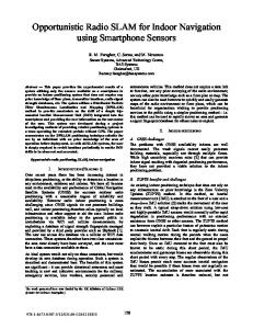
The most important problem when using Bluetooth for positioning is the time uncertainty of response of a Bluetooth device. To discover other Bluetooth adapters and then use their discovery for cell of origin (or even RSSI) it is neccesary to quickly detect other Bluetooth devices that are in the neighborhood. Various design choices of the Bluetooth specification limit the discovery of devices that are near to the user from a few to about 11 seconds. In a mobile environment this can have severe consequences on the position accuracy. One can for example pass a Bluetooth beacon without detecting it at all because its radio range is limited. The average discovery time of a beacon can in some cases be reduced but this usually comes at the trade of power needs. Making a Bluetooth device easier to discover will increase the percentage of time spent in the so called 'inquiry state', which means that the beacon spends less time in an 'idle' state and therefore use far more energy. Many suggestions are done to improve the response time of detecting Bluetooth devices in range, but none of them solve the problem completely or bring the response time back to a very low and predictable amount of time [JIA04] [PET04] [WEL02] [BOH04] [SAL00]. An small experiment was performed at the Guide 60 Percentage ID company with a Bluelon Bodytag Bluetooth 50 47.65 device. This device was set to respond to inquiry 41.16 40 scans as quickly as possible by changing some 30 parameters in such way that the device spent 20 most of its idle time in the 'inquiry state'. The 10 results are given in figure 4. As can be observed, 5 4.2 1.7 0.3 0 under these optimal conditions about 90% of 0-1s 1-2s 2-3s 3-4s 4-5s 5-6s discovering the beacon was done in less than two figure 4: Discovery time of a Bluetooth beacon seconds. The average time to detect the beacon from the start of a Bluetooth inquiry was 1.08 seconds. This is quite fast, but note that in this experiment both the receiving and sending entity remained at the same place. It is very well possible that when a Bluetooth device is found for the first time, its presence will be discovered easier on the next search for Bluetooth devices (by means of caching for example or because clocks have already been synchronized). Therefore the results will vary in an environment where a receiver moves into the radio range of the transmitter. For obtaining signal strength information, another problem of Bluetooth arises: not many devices exist that support the 'inquiry with RSSI' command. Without this option it is always necessary to connect to a Bluetooth device and only after being connected to a device it is possible to read out RSSI values. As this cannot be done during the detection phase this further increases the time to get this RSSI value. An additional problem is that in many cases a connected Bluetooth device will not spend any time in the 'inquiry' state anymore, and thus won't be detected by other devices trying to find Bluetooth devices in their neighborhood. For these disadvantages a positioning system based on Bluetooth beacons can best be classified as 'center of origin' and can thus be used to provide a proximity position. Its wide availability and reasonably low price can be an advantage to use a Bluetooth system.
12
CHAPTER 3: ANALYSIS
OF AVAILABLE TECHNOLOGIES
3.1.3 Global Positioning System The use of the Global Positioning System (GPS) has taken an enormous flight. The accuracy, price and size of GPS receivers make this technology extremely suitable for outdoor navigation. GPS receivers use time-of-arrival technology between the satellite sending its signal and its local time and the moment that signal was received. The receiver also calculates the position of the satellite based on information periodically sent in the same signal. By comparing the position and range of multiple satellites the receiver can discover its own location and produces an absolute (three dimensional) position which is the best 'class' of position to work with. The use of GPS has many advantages such as accuracy, availability, size of a receiver and the fact that a receiver can usually run on batteries for quite some time. The downside of using GPS receivers is that GPS signal usually cannot be received indoors. The satellite signals can hardly penetrate walls or other objects. Improvements for accuracy like Differential GPS (DGPS; using additional ground stations) do not solve this problem. There are amplifiers available for GPS, but they only repeat the signals received on a fixed point (on the roof of a building for example) so that inside the building a receiver won't lose it's positional fix. This can be useful for a hospital for example. An ambulance won't lose its GPS fix, so when immediate navigation is necessary, the drivers won't have to wait outside the hospital for the initial position of the ambulance. From inside the GPS receiver will give the same position throughout the building. An option is the use of pseudolites. A pseudolite is a contraction of the term 'pseudo-satellite', referring to something that is not a satellite but performs a function commonly in the domain of satellites. Pseudolites are most often small transceivers that are used to create a local, ground-based GPS alternative. This is also known as a Local Area Augmentation System (LAAS). The range of each transceiver's signal is dependent on the power available to the unit. Being able to deploy one's own positioning system, independent of the GPS, can be useful in situations where the normal GPS signals are blocked or not available (for exploration of Mars pseudolites were used) [MAS04]. The use of pseudolites do need sub-centimeter calibration when installed at a site and are not common. Another problem is that pseudolites need an adaptation of the GPS signal. The distance from normal GPS satellites to the earth is 20.200 km. When using pseudolites the distance between the pseudolites and the receiver is well within a couple of hundred meter. This renders the standard GPS signal unusable (the chip length of a GPS signal is about 300m). Using pseudolites therefore requires a non-standard GPS receiver [KEE01] [COB97] [MAT05]. Assisted GPS can be another option to enable GPS positioning for indoor use. AGPS describes a system where outside sources, such as an assistance server and reference network, help a GPS receiver perform the tasks required to make range measurements and position solutions. The assistance server has the ability to access information from the reference network and also has computing power far beyond that of the GPS receiver. The assistance server communicates with the GPS receiver via a wireless link. With assistance from the network, the receiver can operate more quickly and efficiently than it would unassisted, because a set of tasks that it would normally handle is shared with the assistance server. The resulting AGPS system, consisting of the integrated GPS receiver and network components, boosts
13
CHAPTER 3: ANALYSIS
OF AVAILABLE TECHNOLOGIES
performance beyond that of the same receiver in a stand-alone mode. This however does not directly lead to good indoor positioning and requires a quite advanced additional infrastructure, which can be unwanted or too expensive. In the future new GPS receivers can be expected which have a better tracking sensitivity [JUN06]. This can open doors for indoor positioning and navigation, but this depends highly on the conditions of the building it is used in. When used at the top floor a better receiver might work, but in a ten story building the signal will still be too weak on the other nine floors.
3.1.4 RFID Radio Frequency IDentification (RFID) is an automatic identification method, relying on storing and remotely retrieving data, using devices called RFID tags or transponders. An RFID tag is an object that can be attached to or incorporated into a product, animal or person [SHE04] for the purpose of identification using radio waves. Chip-based RFID tags contain silicon chips and antennas. Passive tags require no internal power source and therefore have a detectable range of only a few centimeters, whereas active tags require a power source and can be detected over several meters. This range difference and added complexity also causes a large contrast in price. Passive tags are available for a price lower than one Euro per tag where active tags will cost tens of Euros. When passive RFID tags are used it is possible to deploy a very dense and cheap grid of tags, but the range of a passive tag needs a RFID reader to be very close to the tags. For guiding blind people this could be an option [ALG07]. Their white stick could be embedded with a RFID reader, but this specific application needs walking around with a stick which is not always practical for 'normal' visitors in a building. A positioning system based on active RFID tags can support both Center of Origin as well as RSSI as most active RFID tag systems support to readout a RSSI value of the received signal. So using active RFID tags can be used to provide a relative positioning system. The marked for RFID is emerging rapidly creating advantages towards a RFID RSSI based system. Furthermore active RFID tags usually have a battery life-span of more than one year, which makes those an interesting option to use as beacon-devices. The disadvantages of using RFID tags is that it is usually not possible to (easily or dynamically) adjust the output power level of transmission power of a RFID tag. In a dense network of tags or an environment where low transmission powerlevels are necessary, unwanted side effect could occur. For example: if it is not possible to read RSSI values, other users in a building may trigger the RFID tags which will be received by a receiver not initiating that trigger. If no information about the signal strength is available, the receiver may think all the responding tags are near, which is not the case. The other disadvantage, which has an even larger impact: there are only very little active RFID receivers available that can be used in handheld devices. And the devices that are available are very expensive (about 1.000 Euros per receiver). At this moment there seems to be only
14
CHAPTER 3: ANALYSIS
OF AVAILABLE TECHNOLOGIES
one active RFID reader on the market which is available in Compact Flash (CF) housing to be used in handheld computers (the Identec Solutions i-Card Reader). Other readers do either miss a suitable interface or are far too large for embedding in handheld equipment.
3.1.5 Ultra Wideband Ultra-Wideband (UWB) is a technology for transmitting information spread over a large bandwidth (>500 MHz) that should, in theory and under the right circumstances, be able to share spectrum with other users. For positioning means it is only necessary to send a very short UWB pulse. The idea behind using UWB is that problems arising from multipath propagation can be overcome by using a ultra short radio pulse combined with a large bandwidth. The key difference when using UWB is that it is possible to make a clear distinction between pulses that traveled different paths to get to the receiver. The pulse that a receiver sees first may be more attenuated than Illustration 5: Absence of multipath propagation with some other pulses but the UWB characteristics make it possible to UWB clearly distinguish this pulse from other pulses received at the station due to the lack of multipath propagation (Illustration 5: Absence of multipath propagation with UWB). This opens the door to efficient high precision positioning techniques, like ToA, TDoA and AoA. For overcoming this biggest hurdle of multipath propagation, UWB is the ultimate candidate for indoor positioning and navigation systems. There is however a clear downside. The use of UWB for indoor positioning belongs to the frontiers of knowledge. A lot of research is going on at the moment [VOL05] [FON03] [FON04] [FON07] [NEI03] [HAR04] and there is only one company that can deliver a ready-to-use positioning system based on advanced techniques using UWB pulses; Ubisense. The Ubisense system uses a small badge (tag) equipped with a UWB pulse generator and a RF transceiver. In the corners of a room (at least) four sensors must be installed. These sensors should be wired to each other for perfect timing and therefore it is necessary to precisely measure the length of the cables between all sensors upon installation. The system uses TDoA and AoA for calculating the position of a tag (in 3D) with a precision up to 15 cm. If a less accurate system is required, then it is possible to drop the timing wires connecting the sensors and just make use of AoA data for positioning (losing about 20% of accuracy). The fixed placement of sensors and using a mobile tag as a transmitting device make the use of an additional infrastructure necessary if the mobile user wants to know its own position, because only the sensors combined with a Ubisense location server can calculate the position in a room. This makes the system less suitable for fast deployment. Because Ubisense is a pioneer in this market and currently the only player having a fully operational UWB system, the price of the Ubisense positioning platform is high. The mobile tags are relatively cheap (< 100 Euro) but every room needs the installation of at least four sensors. The price of these sensors is about 2000 Euro each and you have to pay for using the Ubisense location software as well (another 1500 Euro per sensor). Therefore setting up a positioning system is mainly convenient for projects where many objects in a single room have
15
CHAPTER 3: ANALYSIS
OF AVAILABLE TECHNOLOGIES
to be located (the coverage area of four sensors is up to 400 m2), and is less suitable for larger indoor areas with many different rooms. The range limitation is mainly due to regulation of restricted output power of UWB devices. Theoretically a larger coverage area is possible, just by increasing the output power of the tags, but this could give more interference on devices using a part of the bandwidth addressed by UWB equipment or bring on potential health risks, which have not been researched yet.
3.1.6 Ultrasound Using ultrasound as a positioning technique has some advantages. Because ultrasound behaves just like audible sound and therefore travels at the speed of sound. This relatively low speed makes it possible to use ultrasound for easy ToA or TDoA determination. For data transmission ultrasound is less suitable because of the nonlinear effects on propogating acoustic waves. As mentioned before a combination of RF and ultrasound is a fairly simple option to use TDoA (in the second meaning of the description of TDoA). A radiosignal is sent at the same time of a ultrasound pulse. The radio signal travels at the speed of light where the ultrasound pulse travels at the speed of sound. Given this difference it is possible to determine the time it took the ultrasound signal to reach the receiver. This can be calculated very accurately (centimeters range). The advantages of using ultrasound (especially in combination with supporting radio transmission) are clear. Besides the relative simplicity of design and the low cost requirements, this technique also comes with a disadvantage; the need for near line-of-sight. Ultrasound waves can hardly penetrate objects (nonlinear effects on propagation) without seeing a significant change in the shape of the waveform. The signal is also easily attenuated by objects. Constructing a positioning system using ultrasound requires quite a lot of beacons, preferable at the ceiling so the chances of line-of-sight are optimal, either in distance range or in the angular range of the transmitter. If all conditions are met ultrasound can deliver a rather accurate relative positioning system. A good example of a system using ultrasound for positioning is 'Cricket' by the Massachusetts Institute of Technology [PRI05]. For centimeter accurate positioning they separate beacons about 4 feet from each other in a grid layout.
3.1.7 Wireless LAN Wireless LAN (WLAN) offers an interesting basis for positioning. The technology supports RSSI readings from broadcasting access points. The availability of WLAN devices is also very high, which can be an advantage as well as a disadvantage. Deploying WLAN access points to cover an indoor location with WLAN signals is cheap and most new handheld equipment has support for WLAN. The proliferation of these access points and devices can be the down side of the technology. Different WLAN devices from different vendors have different signal characteristics. This means that for each brand and type of WLAN access point or network interface card the platform needs to be recalibrated or has some learning trajectory. This can be unwanted. Further, WLAN access points usually send at their maximum output power, which is not always configurable and WLAN devices use quite a lot of power which makes it
16
CHAPTER 3: ANALYSIS
OF AVAILABLE TECHNOLOGIES
impossible to deploy them in area's where only battery power is at hand. Existing WLAN positioning systems, for example Ekahau, also need their own network-infrastructure to communicate. This means that a handheld device will need a constant (WLAN) network connection for receiving its calculated coordinates, which can also be an unwanted or impossible in some buildings. When using WLAN as a basis for positioning, a relative position can be obtained with an accuracy of a couple of meters (center of origin and received signal strengh indication). This is done by using techniques like triangulation and trilateration, but also by using a calculated predetermined footprint of a location and empirical (learning) models depending on what product is chosen as implementation for the positioning engine [WAN03] [LIU07] [LOC04] [LEN04].
3.2 General requirements The Guide ID company has set some general requirements and constraints for a positioning system that can be included into their current platform. Some of these are are also applicable in any handheld application, others are more specific to the Guide ID company or the Guide ID platform. These requirements are in the next paragraph evaluated against the available technologies listed in the previous paragraph. •
Accuracy and range; the positioning system should provide an accuracy of several meters. The system should be able to navigate people in a building e.g. in corridors of a building. For this purpose centimeter-accuracy is not necessary. This also means that a proximity position might be good enough if the accuracy can still be guaranteed for a certain range (up to a couple of meters). An relative or even absolute position is favorable but not a necessity.
•
Portability; the device that is used by the end user of the positioning system must be portable. This means that it should either use technologies that are already available in handheld equipment or if any additional (radio) equipment has to be built in, it should not be too large that it can't be fitted into a handheld's casing. Portability also means that is should be easy for an end user to sue the device. If the transmitting or receiving signals are easily blocked by the user, the portability of the device is low.
•
Low power; the positioning system should be low power as a result of the requirement for portability. A more specific requirement set by the Guide ID company is that it is also preferable if the complete system is battery driven. In some environments (e.g. temporary exhibitions) a mains-powered positioning system can not be deployed easily.
The following requirements can be classified as more specific to the Guide ID company or their platform: •
Costs; the positioning system should be as low cost as possible. This has to be accomplished in aspects like; purchase, assemble, setup, embed, maintain, etc. It can
17
CHAPTER 3: ANALYSIS
OF AVAILABLE TECHNOLOGIES
therefore be preferable to use existing technologies that are already embedded in handheld equipment. The costs aspect can also lead to a to a trade-off in accuracy. •
Support infrastructure; the positioning system should preferably not need a 'support infrastructure'. This means that a handheld device should be able to obtain a users' position as a stand-alone device and that no other infrastructure (e.g. a (wireless) network or a position server) in needed.
•
Deployment and maintenance; the system should be as easy to deploy in an environment as possible. It is preferable if virtually any third party can install the devices, so this also includes the need for things like initial calibration or wiring the devices. The low power requirement also has its impact on this requirement as battery driven devices are generally easier to install. The system should not need intensive maintenance after deployment. It is preferred if the system can run for a long time without any servicing.
•
Scalability; the positioning system should be scalable. This requirement is twofold. On one hand this means that a chosen technology's accuracy can be improved by just adding hardware (e.g. placing more beacons). On the other hand the system must be scalable in such a way that if new inventions are done, the system can be improved by upgrading certain parts (which can be just software upgrades).
3.3 Evaluation of available technologies against the requirements The following schema presents a summary of the investigated techniques against the requirements and constraints given in the previous paragraph. The table shows the main decision making points and an overall mark given per technique. The grades are given from 1 to 5, where 1 means that the technology scores low on that specific requirement and 5 means that the technology scores high on that specific requirement. The overall grade is an average of the given scores. The 'usefulness' column is a grade set for the Guide ID company as some technologies may score very high but have their own limitations when used in the Guide ID platform. Technology
Accuracy and range
Portability Low Power
Costs
Support Deployment and Infrastructure Maintenance
Scalability
Overall grade
Useful for positioning
Infrared
1
2
5
5
4
5
1
3.3
3
Bluetooth
2
4
2
3
4
3
2
3.0
3
GPS
5
5
4
4
4
5
3
4.3
2
RFID
3
3
4
2
4
5
5
3.9
4
US
4
2
3
3
4
4
4
3.4
3
UWB
5
4
4
1
1
1
4
2.9
1
WLAN
3
4
2
3
3
2
5
3.1
3
A short observation of pros and cons for each technology is given below. •
Infrared has a weak range and the need for line-of-sight which affects the portability of the technology when used in a positioning system. Infrared transmitters and receivers require
18
CHAPTER 3: ANALYSIS
OF AVAILABLE TECHNOLOGIES
only very limited power, are low cost and do not need any support infrastructure. The deployment of infrared devices is easy and the devices do not need much maintenance as they can run on batteries. Their usefulness in a positioning system for Guide ID is mediocre as there needs to be line-of-sight between transmitter and receiver but this can also be an advantage. •
Bluetooth has low accuracy (only CoO in most cases) but an average range. Bluetooth devices are common and therefore it scores on portability. Bluetooth by itself is rather low power but a beaconing system using Bluetooth can not be ran on batteries as their discovery system requires much power. The costs are average, deployment of a Bluetooth grid can be costly if many Bluetooth transmitters have to be used. It does not need a support infrastructure but the deployment can be problematic as transmitters cannot be battery driven and need a mains power adapter. The scalability is low. If more Bluetooth transmitters are added, the general response time to inquiries is still a problem. For the Guide ID company the use of Bluetooth can be considered although the absence of battery powered beacons is problematic.
•
GPS has the best accuracy and range. GPS receivers are low cost, low power, very portable and in general not obstructed by the user itself. No support infrastructure is necessary, it does not need any maintenance and is easy to deploy. On scalability the technology scores average as the system can in general not be improved. It is less useful for Guide ID as GPS can not be used in an indoor environment
•
RFID can be used for an average accuracy and range when RSSI can be used. RFID readers for handheld equipment do exist but are very uncommon so it scores average on portability. Active RFID tags are low power and can be battery driven. On costs RFID scores bad as the existing handheld reader equipment is very expensive. The technology does not need any support infrastructure and the deployment and maintenance of RFID tags is easy. The system is also very scalable as increasing the amount of tags in an environment will generally increase the accuracy of the system and existing RFID systems that are not able to read out signal strength readings may in the future support this feature. For Guide ID this technology is very interesting but the cost factor of a RFID reader is a serious issue.
•
Ultrasound can provide good accuracy but the range can be limited because of the nearline-of-sight demands, therefore the portability is low. The technology does not require too much power, has an average cost factor and does not need any support infrastructure either. Deployment, maintenance and scalability are good. For Guide ID the low score on portability is critical which has influence on usefulness.
•
Ultra Wideband can achieve centimeter accuracy in an indoor environment. A AWB transmitter is small and its signal can be blocked easily by a human being but this does not necessarily needs to be a problem if the transmitter is mounted in the handheld casing and if there are sufficient AWB receivers. The transmitters need only little power. Installing a UWB positioning system is however very costly, the system needs a support infrastructure as UWB receivers needs to collaborate together to calculate the position of the user, which
19
CHAPTER 3: ANALYSIS
OF AVAILABLE TECHNOLOGIES
has to be reported back to the user. This also has an effect on the deployment of the system. The scalability is high, adding UWB receivers will generally improve the accuracy. For Guide ID a UWB positioning system is not suitable as it is too expensive to install. Furthermore an UWB system needs UWB receivers in every room that needs to have positioning for the user, increasing the costs even more. •
WLAN can offer about the same performance as RFID in terms of accuracy, range and portability and most handheld devices do have WLAN connectivity built in, but a WLAN Access Point can not run on batteries. The cost of a WLAN access points are average but a support infrastructure might be necessary (the Ekahau positioning engine for example runs on a server, which can communicate the position of a user back to the handheld device). For deployment and maintenance it scores a bit lower than Bluetooth, for the reason that it does not only need mains power to run but the deployment of many Access Points in a certain environment, used only for positioning, might interfere with the performance of existing wireless networks. For Guide ID the use of WLAN for a positioning system is average as the availability of WLAN on handheld devices is an advantage but the power needs and infrastructural needs are disadvantages.
3.4 General conclusion Judging after the comparison table of the last paragraph, an indoor positioning system based on active RFID tags and handheld receivers is the technology that suits best to the needs of the Guide ID company. The disadvantage that has the largest impact not to chose that technology is the price of handheld active RFID readers. A RFID based system will use the Cell of Origin and Received Signal Strength Indication techniques to perform its function. Although more advanced techniques like Angle of Arrival and Time of Arrival will increase the accuracy of the system, those techniques are too complex to use. This accuracy is not needed by the Guide ID company and thus is a system based on CoO and RSSI sufficient. In the next chapters the basics for a new positioning system are proposed based on active RFID tags and receivers. The hardware for these tags and receivers however do not use commercial off-the-shelf tags and reader devices, but are also part of the proposed system. There is aimed at a system that has more or less the same properties of commercially available RFID hardware, but at lower costs by designing and developing an in-house solution. The development of a new system also improves the flexibility of the system as different design choices can be made along the way.
20
CHAPTER 4: SYSTEM
DESIGN AND ARCHITECTURE
4 System design and architecture This chapter describes the first steps taken to develop the hardware for a new positioning system. The first paragraph analyzes what key advantages the system must have for successful development. The second paragraph gives insight in what hardware components have been chosen to fit in the requirements given to the positioning system. The third paragraph presents a functional overview of the components, when used together as a system. The fourth paragraph gives the schematic overview of the wiring of components to accomplish the desired functionality.
4.1 Specific requirements By developing a new positioning system more stringent requirements and constraints can be set. Besides the requirements set in paragraph the Guide ID company has some more restrictive demands for the new system. •
The system must be able to navigate visitors through a building but does not necessarily need to cover the complete building. This means that it is sufficient to help a user navigate at places in a building where assistance is advisable. One could think of places like junctions in corridors or when a user is near to an entrance or exit of a room. In essence a proximity location is sufficient as long as the distance range between a user and the place where the user 'has to make make a new navigation decision' is adequate.
•
The system must be completely battery driven as many of the environments in which the positioning system will be used do not accommodate a mains power supply. This requirement has influence on deployment and maintenance as well as low power.
•
The system must function without the need for a support infrastructure. A handheld application must be able to obtain its position by itself. This is also a bit implied in the first requirement above as the system will not cover the whole building.
•
The system must be flexible. Any parameters that are adjustable should remain adjustable for the Guide ID company to obtain optimal results once the system is deployed. One could think of parameters like 'transmission output power'.
•
All (electrical) components used in the prototype must be widely available. After the prototype stadium it must be possible to create a product that can be put onto the market, using more or less the same components as the prototype.
•
It is preferable that any hardware component can be used in more than one way (e.g. by changing the internal software). From a hardware perspective the diversity of system components should be as low as possible.
4.2 Scenario A scenario is given to outline the way in which the positioning system should perform its
21
CHAPTER 4: SYSTEM
DESIGN AND ARCHITECTURE
function: When a user enters a building with the Guide ID handheld, the user can select a destination on the Guide ID handheld. As soon as a destination is set the handheld calculates the shortest path to the destination and the user is told to start moving in a certain direction. The user starts walking and as soon as the user gets close to a junction or any other point where the system should assist him in choosing the right direction, the handheld computer informs the user what to do next. This can be done by spoken instructions and/or by visible instructions on the handhelds' screen. The user follows its way towards the next 'assistance point' where the handheld provides the user with new directions. This is repeated until the user reaches its final destination. A user may misinterpret the instructions from the handheld. In that case the next 'assistance point' is not the same as had been calculated by the handheld (the user has taken the wrong route). As soon as a new (incorrect) 'assistance point' is reached by the user, the handheld notices this and recalculates new directions from that point towards the final destination. This may imply that the handheld advises to the user to turn around. This approach and the requirements lead to an architecture in which transmitters are positioned as beacons at strategic locations in a building (the 'assistance points'). A handheld computer must then be equipped with a receiver that can pick up signals from the transmitters and differentiate all transmitters from each other. If only the unique identification number of a transmitter can be distinguished this approach would lead to a 'cell-of-origin' positioning system. When signal strength values can also be determined by the receiver, a more precise location can be obtained. Gaining insight in signal strengths can improve the accuracy at which moment the transmitter will trigger certain information at the handheld. A threshold can then be set for each location at which the handheld should provide information to the user of the system. Figure 7 shows a map of a fictive building with a placement suggestion of transmitters (beacons) at strategic locations and the threshold at which the handheld will show location specific information to the user. The arrows indicate the route that the system has calculated for the user to reach room X in the building, following the shortest path. Note that this thesis focuses specifically on the low level aspects of the positioning system (the beacons and receivers) and not on the higher level software that presents the information to the end users.
22
CHAPTER 4: SYSTEM
DESIGN AND ARCHITECTURE
figure 6: Map of a fictive building
4.3 Definition of system components The positioning system that has been developed uses cell of origin (CoO) and received signal strength indication (RSSI) as underlying techniques to enable positioning and navigation. Those techniques are relatively simple and do not require very complex hardware or software for obtaining a system that fits to the requirements of the Guide ID company. The main components that can be distinguished in the system are 'beacons' and 'receivers'. Beacons and receivers are capable of wireless communication and therefore the basis that is needed to create the positioning system. Definition of a beacon: beacons are compact, battery driven devices that regularly transmit their own unique identification number. They can be placed at fixed locations in a building and their purpose in the system is to inform users at those specific locations with specific content (e.g. directions). Therefore they can be placed best at locations where a user of the system 'expects' some output from the system, like intersections. figure 7: Communication between beacon, receiver and handheld
Definition of a receiver: a receiver is a small mobile device that is connected to a handheld computer. It is able to receive the identification numbers sent by the beacons and calculate their corresponding signal strengths. This information is then sent to the handheld. Their purpose is to enable the system to pass the information necessary for
23
CHAPTER 4: SYSTEM
DESIGN AND ARCHITECTURE
positioning (beacon's identifier numbers and signal strengths). The handheld can use this information to present specific content to the end user of the system. Because a handheld (and thus a receiver) is used by the end user, this equipment is not in a fixed location but moves with the position of the end user. Figure 7 shows this interaction of system components. The receivers are kept as simple as possible. They merely operate as an interface between the signals transmitted by beacons and the handheld computer. This is done because of memory constraints on the receiver hardware. The handheld computer is much more powerful and therefore better suited for handling things like threshold triggers and the calculation of route information.
4.4 Architecture This paragraph will give some more insight in how the components interact and contribute to the system as a whole. At first an overview of the system is given and in the following subparagraphs the system will be decomposed to a lower level.
4.4.1 Overview Figure 8 depicts a high level view of the platform architecture. The beacons communicate with receivers and receivers communicate with a handheld computer. As can be observed from the illustration, the arrows depicting communication have arrowheads on both sides. For purposes of positioning, only identification numbers of beacons have to be transmitted to a receiver and then to the handheld. The architecture however supports bidirection communication to increase the flexibility of the system. Communication from a handheld to a receiver is figure 8: Architecture overview used for obtaining receiver specific information (e.g. their own hardware address or for initializing the receiver). Communication between a receiver and a beacon is possible for wirelessly changing a beacon's configuration (e.g. the rate at which a beacon sends its own identifier number or the power level at which the beacon transmits). For 'normal operation' there only needs to be communication from beacon to receiver and from receiver to handheld. The illustration only shows one receiver and multiple beacons. The system obviously supports more handheld devices (equipped with receivers) as these devices can operate as a standalone device for obtaining positioning information. It is drawn this way because the system is viewed as a mobile user would use it. Any other user using the system can be seen as a new instance of figure 8.
4.4.2 Beacon architecture The internal architecture of a beacon at a lower level is given in figure 9. As depicted in this figure, a beacon is composed of two physical hardware components that are necessary for transmitting the beacon's identification number. The transceiver figure 9: Beacon architecture
24
CHAPTER 4: SYSTEM
DESIGN AND ARCHITECTURE
is used to transmit data (the identification number) wirelessly to the receivers (but the transceiver is also capable of receiving data wirelessly; it can operate as a radio transmitter as well as a radio receiver hence the name transceiver). The microcontroller is used to control the behavior of the transceiver. In more detail; a microcontroller creates data packets with its own unique identifier number and transfers this packet data to the transceiver (using the industry standard SPI interface). Then it signals the transceiver that a packets is ready for wireless transmission. The transceiver at its turn broadcasts the packet into the air (independent of any knowledge of receivers in the neighborhood, so even if nobody is listening, the packet with beacon identification information is transmitted). Note that another important physical component is necessary to enable wireless communication; an antenna, but since this device does not play any active role in the communication it is not drawn in the figure. In this figure more than one receiver is drawn as the data broadcast by one beacon can be received by more receivers simultaneously (or even by none).
4.4.3 Receiver architecture A receiver consists of the same hardware components as a beacon (figure 10). This meets up to the requirement that hardware components should be reused wherever possible to keep development and production costs down to a minimum. There is however one hardware component added to the system which makes communication between the receiver and the figure 10: Receiver architecture handheld device possible; a RS232 line driver but this part does not perform an active role in the communication either (it only translates signals from microcontroller levels to RS232 levels) and is therefore left out in the figure. The RS232 connection is an industry standard which is still widely used as communication interface between all kinds of devices. A handheld device generally has at least one 'serial port' to which the receiver can be connected. The transceiver listens for incoming data packets from beacons. When a data packet arrives it will be decoded from wireless signals into a binary array (the packet) and the signal strength at which the reception was done will be appended to the data. After this, the transceiver signals the microcontroller that new packet data is waiting. The microcontroller will transfer the data from the transceiver to the microcontroller and then the microcontroller sends the data through to the connected handheld for further processing. This is not done in one step as for configuration purposes the packet has to be inspected and reacted to even before it is transferred to the handheld.
4.5 System behavior For the system behavior the same approach is applicable as for the description of the architecture. At first an overview is given on how communication takes place. From there a
25
CHAPTER 4: SYSTEM
DESIGN AND ARCHITECTURE
refinement is made how the lower level system components interact which each other to obtain the right functionality of the positioning system.
4.5.1 Overview As said, standard communication between beacons and receivers takes place even if no receiver is present. This kind of broadcasting is chosen because of power constraints at the beacon's side. As a beacon is a stand alone device that runs on batteries, the batteries should not be drained too fast to maintain a usable system and meet the requirements set for the positioning system. Sending or receiving signals (data) takes a lot of power while 'sleeping' is very energy efficient. Therefore there is chosen to create beacons that do only periodically send their own identification number and then fall asleep again. An approach where beacons would only transmit their information when a receiver is in the vicinity seems like a more energy efficient approach but a beacon can only know that a receiver is near by letting the beacon periodically listens for receivers that transmit some kind of 'wake up' signal. Because of the very short time it takes to send a radio signal, the beacons need to wake up very often to look for 'wake up' packets so the packet will not be missed. This would cause the beacon not to respond to a receiver that is nearby. It is more energy efficient to just transmit a packet and then fall asleep again until the beacon's next transmission. Another downside of the wake-up approach is that if there is chosen for a longer radio signal (by means of a longer air-time) to wake-up the the beacons, the transmission medium (the 'air') is 'polluted' with these long wake-up packets. Other beacons or receivers in the building may suffer from this because it interferes with other devices trying to communicate. To meet to the flexibility requirement, the beacons must be configured wirelessly. To obtain this there is chosen to implement a strategy where beacons periodically signal receivers that they are in a 'configurable' state. Instead of transmitting their 'normal' packet containing their unique identification number and fall asleep again, they send a slightly different packet. After this, the beacon does not fall asleep immediately but starts listening for incoming radio traffic for a very short period of time. A receiver could pick up this special state and immediately respond to this packet by sending a request to the beacon to stop its normal behavior and go into configuration mode. More about this is in the 'configuration behavior' chapter
4.5.2 Normal beacon behavior An overview of normal behavior between a beacon and a receiver is given in the sequence diagram shown in figure 11. Normal behavior must be interpreted as the behavior a beacon exhibits to let the positioning system function, which means that a beacon must sent its unique identification number periodically. This unique identification number is transmitted in a so called 'hello packet' to any listening receivers that reside within communication range of that beacon. figure 11: Sequence diagram of standard beacon behavior
26
CHAPTER 4: SYSTEM
DESIGN AND ARCHITECTURE
In the default situation there is chosen to transmit these 'hello packets' six times per seconds. This value is determined by the factors energy efficiency and a hardware constraints (watchdog timer) and can be configured with a certain n: approximately each
1n255 to send a packet
1
n⋅12 second (so the default is n = 2).
To indicate that a beacon will not fall asleep immediately after sending the identification number, a 'hello with wait for reply' packet is defined. This packet can be used to signal receivers that a beacon did not go to sleep immediately after sending the packet but stays awake for a very short time to be able to receive incoming configuration requests. A parameter to obtain this behavior is used to determine how often the beacon will send a 'hello with wait for reply' packet. The 2-byte parameter can make the beacon stay awake for configuration after each transmission (parameter set to one) up to once every 65534 normal 'hello packets'. The parameter set to zero will disable this functionality. Figure 12 shows the behavior with the parameter set to three. In the default situation, this parameter figure 12: Normal and 'stay awake' is set to 180, which means the beacon listens for configuration packet sequence requests approximately every 30 seconds. This value is chosen because of energy constraints (stay awake too often requires too much energy) and convenience (when changing a beacons parameters one does not want to wait for 10 minutes to configure just one beacon). The state diagram how a beacon functions is presented in figure 13.
27
CHAPTER 4: SYSTEM
DESIGN AND ARCHITECTURE
figure 13: General state diagram of beacon operation
4.5.3 Normal receiver behavior As mentioned in the architecture of the receiver, the receiver is some kind of 'service-hatch'. Incoming packets get their received signal strength appended by the transceiver. The microcontroller reads out this data and then sends it to the handheld computer for further processing, so for positioning purposes no checks are done by the microcontroller on the data from the transceiver. Here also applies; normal behavior is the behavior that a receiver exhibits to obtain the positioning system.
figure 14: Normal receiver behavior
This is shown in figure 14 where the two communication steps are drawn. One step for receiving data from the beacon by the receivers' transceiver hardware and another step for transferring the data to the handheld. Note that the RSSI data is added by the receiver's hardware itself and is evidently not transmitted with the 'hello packet' by the beacon.
4.5.4 Handheld to receiver communication Almost all communication is initiated by a sending beacon that will be received by a receiver and send through to the handheld. For initializing the receiver and configuration purposes it is also possible to send data to from the handheld to the receiver. If a handheld wants to
28
CHAPTER 4: SYSTEM
DESIGN AND ARCHITECTURE
communicate to a receiver it first has to send a special 'attention' packet. This is necessary because the microcontroller cannot handle multiple tasks at the same time and the built in serial routine cannot handle a full duplex connection. It might be the case that at the moment the handheld wants to transfer data to the microcontroller at that same moment the microcontroller is transferring data to the handheld. In that case the 'attention' is detected (it generates an interrupt) but the microcontroller is not capable of listening to what the handheld has to say. Therefore it will first finish the job that was in progress and then it blocks the transceiver from receiving incoming packets and sends a 'ready' reply to the handheld. From there the microcontroller is only listening to incoming data from the handheld. The handheld recognizes the 'ready' response and knows that the microcontroller is ready for receiving commands from the handheld. A 'request settings' can be sent for example and the microcontroller will reply with a corresponding packet. After this, the receiver falls back in its normal behavior and starts receiving packets from beacons again. This example is drawn in figure 15. If no other job is in progress at the moment an 'attention' is sent by the handheld, the microcontroller will reply immediately with its 'ready' response.
figure 15: Handheld to receiver communication
4.5.5 Requesting configuration A beacon can be configured but as stated in paragraph x a beacon is normally not receptive to any incoming traffic. The 'hello with wait for reply' is the exception to this but any entity that wants to contact the beacon must respond very quickly as a beacon will only stay in 'receive mode' for a very short period of time. To make sure that a beacon will be addressed within the time it can receive data, a mechanism is set up to make sure that there is as little time loss between a beacon signaling that is is in 'receive mode' and a receiver responding to this, the
29
CHAPTER 4: SYSTEM
DESIGN AND ARCHITECTURE
receiver can accomplish this task without intermediate intervention of the handheld. The only thing the handheld has to do is to request the receiver to configure a certain beacon. This process is depicted in figure 16.
figure 16: Request a beacon to go into 'configuration mode'
A receiver is in 'normal operation' just as the beacon. An 'attention' can be sent to signal the receiver for a request from the handheld. As soon as possible the receiver indicates that it is ready. The handheld at its turn tells the receiver that configuration of beacon X is required. From that moment the receiver will wait for the 'hello with wait for reply' packet from the requested beacon, indicating that the beacon is listening for incoming traffic. As soon as that packet arrives at the receiver, the receiver takes action and sends a request to the beacon to go into 'configuration mode'. The beacon will respond to this request and state that from that moment it is in configuration mode. This indication is passed through to the handheld so the handheld knows that the beacon can now be configured. The receiver will however resume its normal operation and starts to listen to any incoming data again (which can be 'hello' packets from other beacons nearby).
4.5.6 Configuration itself The configuration itself can be seen as a simple stop-and-wait protocol. A handheld can get or set settings from the beacon by sending the appropriate packet. The receiver will transmit this packet to the beacon and a beacon will respond to the request. This response is again received by the receiver and passed on to the handheld. Note that an 'attention' has again to be sent first for every request as the receiver is in normal operation mode. A beacon can also be signalled to quit configuration mode. When this is done the beacon will restart and resume its
30
CHAPTER 4: SYSTEM
DESIGN AND ARCHITECTURE
normal operation (if necessary with the new settings). A beacon also has a timer mechanism built in that if no configuration requests is received for a period of time, the beacon will restart its normal operation. This is done because in some cases packets may get lost or the administrator of the system may forget to quit the configuration mode. During the configuration process the beacon is in 'receive mode' so it will use a lot of energy and possibly drain the battery if the configuration mode is not exited at a certain moment. An example of configuration of beacon X is given in figure 17.
figure 17: Configuration of a beacon
31
CHAPTER 5: SYSTEM
IMPLEMENTATION
5 System implementation This chapter outlines decisions that were made to implement the prototype. The first part will specify the components used to create the basis for the positioning system and all components are verified against the requirements that are set for the Guide ID positioning system. The second part of the chapter will give more detailed information about the way the entities communicate in the system. The last part presents a filter that is used to 'flatten' the collected RSSI values to give more accurate results.
5.1 Hardware implementation As described in the previous chapter, the key to the positioning system is to obtain signal strength information from packets that are received at the handheld computer. The two main components used to do this are the transceiver and the microcontroller. The transceiver is used to handle all low-level packet functions and make the system able to transmit and receive data at a specific radio frequency. The microcontroller on one side of the system controls the transceiver and generates packets that can be transmitted at a specific interval. At the receiving side of the system, the microcontroller will handle incoming packets and send the packets to the handheld computer.
5.1.1 CC1100 Transceiver chip For transmission and reception of packets the CC1100 transceiver chip from the ChipCon company in Norway was chosen. Recently Texas Instruments (TI) bought this company and merged their products into their catalog. Full support is now given by all the Texas Instruments offices around the world. The fact that a large company distributes these transceivers is one of the reasons for choosing this transceiver. It is easy to obtain those in The Netherlands and the price per transceiver is also low. For RSSI calculations this transceiver is very interesting because it supports 8-bit digital RSSI reading with a resolution of 1/2 dB per bit. This is very useful for the purpose of reporting back RSSI values. Competing transceivers (for example the Nordic nF903) does not support RSSI reading at all and the predecessor of the CC1100 (the CC1000) does only support analog RSSI which make interfacing the transceiver to a microcontroller for the specific purpose of RSSI measurements a lot more complex than when it is done in the hardware of the transceiver itself. For transmission the full range of ISM/SRD bands can be used in the CC1100. The device is configurable to use the range of 300 up to 1000 MHz, making its design very scalable. The only (hardware) condition for selecting a frequency is to take into account that all transmission frequencies need specific antenna characteristics. For each different output frequency the physical and electrical design of the antenna path (balun) is different. Therefore it is necessary to choose an operating frequency band first. For the proposed system there is chosen for the 433MHz. ISM band. This band is mainly used by radio amateurs and RF remote controls. It is also possible to choose for the 868 MHz. ISM on the data from the transceiver band.
32
CHAPTER 5: SYSTEM
IMPLEMENTATION
The fact that the design complexity of the antenna path balun increases when the transmission frequency increases was decisive to choose for a low frequency. In the future this can be changed at the cost of a new PCB design. A 2.4 GHz. version of the CC1100 also exists. This transceiver (CC2500) is pin and instruction compatible with the CC1100. So designing a future 2,4 GHz. version is possible taking into account that the antenna path must also be changed and a prototype can not be made by hand that easily. Another advantage of the CC1100 is its ready-to-use transceiver. There is no advanced knowledge on radiographic data transmission required or how packets should be sent from one device to the other. The transceiver is equipped with full packet handling capabilities including preamble generation, sync word insertion and detection, address check, flexible packet length and automatic CRC checking. The basic idea of the transceiver is that a software implementation only needs to initialize the transceiver with parameters like transmission frequency, bitrate, encoding type, etc. After this initial setup the software only needs to write packet data to the (64 byte FIFO) buffer of the transceiver and put it in transmit mode. The transceiver will then automatically send the data that resides in the buffer, without any other interaction of the microcontroller or other hardware components. For receiving packets a similar setup procedure can be followed, putting the transceiver in 'receive' mode, which will automatically start filling the buffer with incoming packet data. Receiving packets will require about 15,6 milliamperes, sending a packet at +10 dBm about 28,8 milliamperes and when in sleep mode the transceiver only requires a couple of microamperes. The CC1100 can be programmed to use data rates from 1.2 up to 500 kbps. A high data rate shortens the 'air time' and therefore saves valuable battery capacity. The wide operating voltage of 2.0 – 3.6 volts further enable battery-powered beacons. Communication between the transceiver and microcontroller will take place using the industrial standard Serial Peripheral Interface (SPI) and is capable of communicating at approximately 8 megabit per second. This enables the device to handle the relatively high 'over the air' data rates. The capability of SPI communication has influenced the selection of a microcontroller because a microcontroller natively supporting this inter-chip communication standard is preferable over a more difficult to implement 'bit-banging' solution.
5.1.2 MSP430F2013 microcontroller The first criterion for selecting a microcontroller is the availability of the Serial Peripheral Interface. The Texas Instruments MSP430F2013 has this interface and was selected for several reasons: The microcontroller has a very low pin-count (depending on the packaging only 14 pins). This means that for use in a beacon hardly any pins will be left unconnected. This decreases the size of the PCB and reduces power needs as well. For a prototype the size of a PCB is not important but in later production models the same setup should be used and implemented on a Compact Flash adapter card which is only 43x36x50 mm in size.
33
CHAPTER 5: SYSTEM
IMPLEMENTATION
The second reason is that the MSP430F2013 is an ultra-low power microcontroller in design. In active mode (1 Mhz.) the microcontroller needs a current of only 220 microamperes. It has almost the same voltage range of the CC1100: 1.8 – 3.6 Volt. The microcontroller can run at different speeds, depending on the mode it is in. In active mode the default speed is 1 MHz. but it can also operate at a top speed of 16 MHz at the trade of higher power consumption. It is equipped with 2048 + 256 byte flash memory and 64 bytes of RAM. This seems very little but since the transceiver supports most low-level packet handling capabilities this is adequate. It features a 16-bit RISC instruction set, 8+2 general purpose input/output pins with configurable pull-up/pull-down resistors and interrupt capability. Some of the pins can be reconfigured for a specific function (like the SPI interface). A timer and watchdog timer are also present. The MSP430F2013 is also easily available in The Netherlands and since Texas Instruments bought the ChipCon company there is more and more information available on integrating Texas Instruments' MSP430 architecture with the ChipCon transceivers. Besides this Texas Instruments released a development kit for the MSP430F2013 which contains a complete integrated development environment (IAR Workbench) capable of in-line debugging and a USB stick with a detachable MSP430F2013 microcontroller that can run autonomously after it has been programmed with the programmer part of the USB stick.
5.1.3 Saft Lithium battery Battery operation is important in the proposed positioning system. The beacons should be able to operate for a long time using a battery as power source. For the system there has been chosen for Saft batteries as they produce a wide range of Lithium based batteries. Lithium batteries have a nominal voltage of 3.6 Volt which is ideal for the positioning system as all hardware components can handle an input voltage up to 3.6V. This means that the hardware can be interfaced to the battery directly without the need of any voltage regulating equipment. In the prototype beacons a Lithium-thionyl chloride C-size battery is used with a capacity of 5500 mAh [SAF07]. If for the production beacons a smaller sized battery is needed, there also exist various A and AA-sized Lithium cells at the trade of capacity and thus runtime of the beacons. Rechargeable batteries are not recommended as they have a higher self discharge time, which means that the batteries will lose their capacity quickly even when they are not used. For the nowadays common NiMh batteries this effect can lead to a discharge of about 1% each day so a battery will not retain its initial capacity for a very long time even when it is not in use. The Saft battery has less than 3% self discharge after one year of storage [SAF07].
5.1.4 SP3232 Serial linedriver For prototype connectivity of the receiver to a handheld computer a serial connection is used. The microcontroller operates in the 3 Volt range but because RS-232 communication uses a positive/negative voltage for encoding a logic 0 and a logic 1, a serial line driver is needed. The Sipex SP3232 is a standard 3 Volt serial linedriver (pin compatible with the better known Maxim Max3232 linedrivers) that converts TTL signals to true RS-232 voltage levels. The
34
CHAPTER 5: SYSTEM
IMPLEMENTATION
microcontoller's serial input/output levels will be shifted to the corresponding RS-232 levels to interface it to the handheld computer.
5.1.5 OXCF950 For use in the final product the serial interface should be replaced to an interface that can fit into a handheld computer. Most handhelds now feature a Secure Digital slot as well as a Compact Flash slot. The Compact Flash slot should be large enough to house the chosen hardware, except for an antenna that must be mounted on the outside of the handheld device. The Oxford Semiconductors OXCF950 provides a (TTL) RS232 to Compact Flash interface. When the receiver is inserted into the handheld computer, the operating system will detect a new serial port. This port can then be used for communication between the handheld computer and the receiver. This chip will not be used in the prototype but is considered for the production phase as it is important for the design of the system that it can actually be built into a proper casing after the prototype stadium.
5.1.6 Antenna design An important aspect of a communication device is the design of the antenna. A badly designed antenna will have a severe impact on the performance of the device as a whole, or won't even perform its function at all. There are many designs to choose from, each with its own advantages and disadvantages. For the final product an integrated antenna would be favorable. It is possible to etch an antenna into the PCB of the beacons to keep them small. But because antenna design is very complex matter, the prototype will have a standard quarter wave ground plane antenna (quarter wave 'whip'). In this design the antenna is formed by a vertical wire that has a quarter length of the waveform. For a 433 MHz. design the corresponding wavelength is 69.24 cm1. A quarter wave antenna should be 17.3 cm in length for optimal performance. Because the antenna stands on a ground plane, the radio waves are reflected and so this design performs like a standard, but larger, dipole antenna. For RSSI detection it is important to have a good signal to start with. A badly designed antenna has very low gain, resulting in a bad signal strength at the receiver. The better the signal strength is at the transmitter, the better the system will perform and the higher the detectable range will be. The quarter wave antenna has a gain of up to 2dBi and performs in an omnidirectional way which is favorable when used in a positioning system as the strength of the signal radiation should be the same in all directions. A 17 cm long antenna is sufficiently short to use in the prototypes for beacons and handheld receivers.
5.2 Radio communication For successful radio communication a couple of parameters must be set. The following paragraphs discuss these parameters and why they are set in certain ways.
5.2.1 Basic radio communication parameters 1
=
c f
wavelength = speed of light / frequency
35
CHAPTER 5: SYSTEM
IMPLEMENTATION
For simplicity the Guide ID Positioning System uses a fixed frequency for data communication. The advantage over frequency hopping systems is that all beacons and receivers are able to communicate without any setup procedure between a beacon and a receiver to initiate communication. Any packet sent by a beacon on the carrier frequency will be received by any listening receiver. It keeps the system simple but can on the other hand be more subject to interference from other devices using the same frequency. As described in the paragraph about antenna design, the carrier frequency is based in the 433 Mhz and actually locked to 432.999817 MHz. (not taking slight variations in stability of the clock oscillator into account). From that base frequency multiple 'channels' can be chosen for transmission. Each channel up will add 200 kHz. to this base frequency and can be used if the chosen channel has too much interference or causes too much interference. As a default all devices in the system use channel 0 for communication but this can be changed easily to provide flexibility in the system. The bitrate that is chosen for the system is set to 250 kbps. The main reason to select such a high bitrate is that a high bitrate will only occupy the medium (the air) for a short time, compared to lower bitrates. The shorter the 'airtime', the longer the battery life. Other advantages are that a shorter airtime will decrease the chance on collisions of packets sent by other beacons (or even other devices occupying the same frequency band). The downside of using a higher bitrate is that the sensitivity of the receiver gets worse. For a 1.2 kbps bitrate the sensitivity of the transceiver is -110 dBm where for 250 kbps the sensitivity is -93 dBm. Another disadvantage is that higher bitrates typically occupy a wider bandwidth which may cause problems with other devices communicating in the same band. The chosen bitrate requires a bandwidth of 541 kHz. Although 500 kbps is supported by the transceiver, Texas Instruments warns that a 500 kbps will suffer from an increased packet error rate. Another reason for choosing 250 kbps as a maximum bitrate is that the serial interface to the handheld computer only supports up to 115.2 kbps. In theory this could overload the buffers of the transceiver as data can only be sent to the handheld device on a lower bitrate, but the overhead caused by the 'air-to-air' protocol to guarantee proper wireless data transmission prevents this from happening. For encoding data onto the carrier frequency there is chosen to use Minimum Shift Keying (MSK) which is the default setting in the support program (Texas Instruments RF Studio) to obtain reliable 250 kbps operation. The parameters suggested by the program are also optimized for sensitivity. In general is MSK advisable to reduce problems caused by non-linear distortion. The transceiver supports various transmission power settings, ranging from -30 to +10 dBm. All transmissions in the system are set to +10 dBm (which comes down to 10 mW) to optimize the detectable range of the devices. This settings can also be changed easily to provide more flexibility to the system. It might be appropriate to decrease the transmission power in an environment where many beacons overlap each others transmission range or where regulatory obligations prevent the system to transmit at full power. Decreasing the transmit power can also be done to extend the battery life of a beacon. Current consumption at +10 dBm is typically 28.9 mA and for 0 dBm output power, the current consumption falls down to 15.5 mA. So the trade off that was made is based on detectable range and not on power
36
CHAPTER 5: SYSTEM
IMPLEMENTATION
requirements.
5.2.2 Transceiver low level packet handling The transceiver includes all features to completely handle incoming and outgoing packets. Some of those need some explanation to understand how the complete system will work. The transceiver has a built-in demodulator, symbol synchronizer and data decision circuitry (figure 18). These circuits are optimized to enhance the performance of the transceiver. In our case where MSK modulation is used, the demodulator will compensate for the offset between the transmitter and receiver frequency, within certain limits, by estimating the center of the received data. figure 18: Transceiver block diagram
Bit synchronization algorithms extract the clock from incoming symbols. The algorithm requires that the expected data rate is programmed at forehand. It re-synchronizes continuously to adjust for errors in the incoming data rate. Byte synchronization is achieved by a continuous search for a 'synchronization word' (sync word). The sync word is configurable 16 or 32 bit field that is automatically inserted at the start of the packet by the modulator in transmit mode. The demodulator uses this field to find the byte boundaries in the stream of bits. It also functions as a system identifier, since only packets with the correct predefined sync word will be received. For the Guide ID system, a 32 bit field is chosen which is recommended for high data rates. Besides the sync word the packet handling hardware will known when to start listening to a packet by listening for a number of preamble bytes. These bytes contain an alternating sequence of ones and zeros (01010101...). At least 2 preamble bytes can be inserted at the start of the packet, with a maximum of 24. For the Guide ID system there is chosen to use 4 bytes, which is the recommended amount for reliable communication at 250 kbps. The RSSI value is an estimate of the signal power level in the chosen channel. This values is based on the gain setting in the receive channel and the measured signal level in that channel. At the moment the demodulator detects a sync word the RSSI value is frozen until the packet is completely received. The transceiver can be configured to include information from the 'link quality indicator' (LQI) and the RSSI value in the packet data. This data will then be present in the receive FIFO buffer of the transceiver. For maintaining a good lock at the center frequency the system must be calibrated at least at power on. The beacons are configured to auto-calibrate after sending four packets. This is a function that is also supported by the transceiver itself and done so to keep the interface to the microcontroller as simple as possible.
5.2.3 Transceiver high level packet handling 37
CHAPTER 5: SYSTEM
IMPLEMENTATION
For complete packet handling the transceiver also supports forward error correction, interleaving, data whitening and CRC checking. The latter is used in the Guide ID system to simplify the functioning of the system. The transceiver has two programmable general purpose pins that can be configured to function as interrupt. When receiving a packet the transceiver will check the CRC of the packet and if the CRC matches an interrupt will be given on one of the pins (GPO0) that a packet is ready and waiting in the FIFO buffer. The other pin (GDO2) is configured to generate an interrupt when the FIFO buffer overflows. Theoretically this should never happen but when debugging the system is is handy to have this interrupt functioning as any breakpoint in the system would cause the transceiver to pile-up packets in the buffer until it overflows and stops to respond. With handling this particular interrupt the transceiver can be reset and started to receive mode again. The transceiver also supports an optional address check byte. This byte can be used by devices in the same channel to ignore incoming packets that do not have the address specified at this position. The values 0 and 256 are used as a broadcast address and are always let through by the transceiver. The address byte increases the performance of the system dramatically as the receiving part stops receiving when the address byte does not match. In the Guide ID system the address byte is used to denote the 'beacons' and 'receivers'. This is sufficient as a beacon will generally only send data to any receiver and vice versa. Especially: the beacons will (when in receive mode) not be 'disturbed' by packets sent to a receiver and receivers will not analyze any incoming packets that are sent to a beacon. because an incoming packet is not further processed the microcontroller does not get an interrupt and can stay in sleep mode, saving power and processing overhead. The transceiver is configurable to support any variable or fixed packet length, even a length that is larger than the FIFO buffer itself. This mode can only be supported if the microcontroller start reading out bytes from the buffer while the transfer of a packet is still in progress. For the Guide ID system there is a fixed maximum packet length defined of 16 bytes. This is done to keep the system simple and more reliable. The length of a packet is also one byte that resides in the header of the packet sent by a transceiver. The receiving transceiver compares the value against the defined maximum packet size. If the incoming packet is longer than the receiver supports, the packet is discarded completely and no interrupt will be given to the microcontroller. The following steps are taken by the transceiver when a complete, valid packet comes in: 1. 2. 3. 4. 5. 6. 7. 8.
Preamble is detected The sync word is detected The length byte is checked The address byte is checked The packet data is received The CRC of the packet is computed and validated The LQI and RSSI values are appended to the packet data in the buffer Generate an interrupt on the GPO0 pin
38
CHAPTER 5: SYSTEM
IMPLEMENTATION
The packet format that the transceivers use to communicate has the following structure (figure 19: Transceiver packet format): Preamble bits (1010...1010)
Sync word
Data Length
Destination Group
Payload Data
CRC
4 octets
4 octets
1 octets
1 octets
0..15 octets
2 octets
figure 19: Transceiver packet format
The dark gray parts denote specific hardware settings used by the transceivers to enable communication on the low level side of the transceiver. The light gray parts are used by the transceiver's higher level packet but are (when a packet is valid) also sent to the microcontroller for further processing. So the preamble, sync word and the CRC are stripped from the packet data in the buffer of the transceiver. The white part is the actual packet data that can be used by higher level protocols for data communication. This data is completely transparent to the transceiver. The microcontroller has to create this data upon sending a packet and analyze the contents when receiving a packet. Note that the appended LQI and RSSI value are not part of this packet structure as it is appended to the packet afterwards and not sent over-the-air.
5.2.4 State machines The transceiver can be put into receive or transmit mode by putting its internal state machine into the specified state. To understand how the transceiver operates and how its behavior is controller by the microcontroller the simplified state transition diagram is given in figure 19: Transceiver packet format. The state machine is copied from the CC1100 data sheet [CHI06] and also gives some insights in the transceiver's power requirements of the various states.
Illustration 20: Simplified transceiver state diagram
From this a state machine can be given for the beacon as well as the receiver.
39
CHAPTER 5: SYSTEM
IMPLEMENTATION
The internal operation of the beacon is depicted in figure 21. Left of the line, the state machine of the microcontroller is given and right of the line the state machine of the transceiver is given. The line illustrates the concurrency of both components. Both components start in the 'sleep' state for minimal energy consumption. When the microcontroller wakes up it performs a couple of functions to control the transceiver which enable the transceiver to send a packet. When the processes is finished, both components fall asleep again until it is time to send the next packet.
Although the maximal bitrate for the CC1100 transceiver is 500 kbps
figure 21: Beacon internal state machine
5.3 RSSI filter To improve the quality of signal strength readings, a filter has been developed. Without the filter a lot of jitter is visible . This hinders the accuracy when using signal strength readouts for positioning. The most significant errors in signal strength in a certain environment are caused by the environment itself. All kinds of objects (but mostly metal objects) in the environment cause multipath propagation which ultimately leads to 'dark spots' at certain locations in the environment. At these locations the signal strength drops dramatically or vanishes completely (i.e. the signal is below the sensitivity threshold of the receiver). The existence of this effect in an environment is shown in the evaluation chapter. Moving objects are also influencing the signal strength at a receiver. People may block the signal from a beacon, causing a much lower signal strength readout than would be expected. These effects usually have a temporarily effect, as people tend to move within a room (at least the person that is using the navigation system). The transceiver itself may also cause a bad readout of RSSI values. Sometimes the wrong signal strength is reported, probably caused by locking the RSSI value when some strong signals remain in the channel or in adjacent channels. There is no evidence what causes these faulty readings, but as they only sporadicly occur it is not necessary to try to completely eliminate this effect. The filter tries to optimize the readings by making three assumptions about the environment:
40
CHAPTER 5: SYSTEM
– – –
IMPLEMENTATION
People using the navigation system are moving towards a (new) beacon People using the navigation system are moving in general (thus not standing still) The signal strength in an environment can only be weakened by objects in that environment and not be amplified.
In general this leads to the conclusion and the target objective of the filter that the received signal strength of a beacon should increase when a user is moving towards that beacon. Ideally the signal strength at the receiver follows a curved line as shown in figure X. Because of the jitter effects described above this is usually not the case. Therefore the filter tries to drop 'bad' readings and keep 'good' readings but this only works under the assumptions given above. In words explained, the filter remembers the last n signal strength results of a beacon and determines the m highest values of these n results. Then it calculates the average of those m highest values. This average can then be used by the navigation software for further analysis (for example: check if this value is below or above a beacon's threshold on a certain map). This is done for every new packet that is received thus it creates some kind of 'moving average'. The parameters n and m depend mainly on the amount of packets a beacon sends every second. A higher n may increase the quality of the filtered RSSI value but might also create a lag on the RSSI value to go down again (see example 1 below). The parameter m has to be selected carefully as it takes m good signals to increase the RSSI reading. In an environment where beacons send their packets with a large interval a m that is too large may cause the RSSI value to be unable to increase to a certain threshold (example 3). Some examples: Example 1: If n=21 and m=5, the last 21 measurements are used over which the average of the 5 highest measurements is calculated. Imagine that a beacon sends 3 packets per second and that a user has passed the beacon (so the RSSI readouts of the beacon are decreasing). This causes a lag of 7 seconds (21 / 3) for the filtered RSSI value to go down again as it takes 21 new (lower) values to get the highest 5 measurements (taken when very near to the beacon) out of the filter. This may cause overlap of RSSI thresholds on a map. Example 2: If n=10 and m=1, the last 10 measurements are used over which the average of the 1 highest measurements is calculated. The beacon sends a packet twice per second. Imagine an errornous high RSSI reading from the transceiver. This causes the filter to return a high filtered RSSI value for 5 seconds (10 / 2), which may cause the navigation software to trigger a message that should not have been triggered at that location. If m was larger (for example 3), the average would have been calculated over the highest 3 measurements in which one wrong value would have a smaller impact to the average.
41
CHAPTER 5: SYSTEM
IMPLEMENTATION
Example 3: n=5 and m=5. If a beacon only sends one packet every second, the filter uses the highest RSSI values from the last 5 seconds. If a user passes a beacon, the results of the last 4 seconds are also accounted by the filter, which may cause the average to be far smaller than the actual RSSI value close to the beacon. This may leave the average too low to reach a certain threshold. The filter has been implemented this way because it can deal with the temporary effects of bad signal readouts, caused by the black spots in the environment as well as bad readouts by people blocking the signal, but it is obvious that the assumption that people using the system are moving (and moving towards a beacon) is crucial to the filter. If they are not moving and for example standing still in a black spot, the filter collects data that is not representative for that location. For the Guide ID navigation system this filter is sufficient as it only needs to trigger at certain thresholds.
42
CHAPTER 6: EVALUATION AND
RESULTS
6 Evaluation and results In this chapter the presented solution for the Guide ID navigation system are evaluated. The first paragraph show some results that were obtained by running real-life tests with the beacon and receiver system. The second paragraph shows the results that can be obtained by using the proposed filter algorithm. The third paragraph presents the evaluation of power that is used by the beacons. In the fourth paragraph the system is evaluated against the requirements that were set. The last paragraph presents some suggestions for further research and improvements that can be considered using the current system.
6.1 Evaluation of the system In this paragraph some results are presented which are obtained from RSSI data that has been collected in 'real-life' tests in the Guide ID building. All graphs are produced by using real measured RSSI-values and evaluating these values with a Matlab script. The script is also capable of generating graphs using different filter settings. The first graph (Illustration 22: Moving towards a beacon) is made by recording the measured RSSI values in a corridor. During this experiment the receiver moves towards the beacon in an uniform motion at a constant speed of approximately 4 km/h. The beacon transmits its unique identifiying number approximately 12 times per second. The distance that is covered between the first and the last measurement is 16 meters away from the beacon up to the receiver touching the the antenna of the beacon. Both receiver and beacon are approximately 1 meter above the floor and 2 meters below the ceiling during the experiment.
43
CHAPTER 6: EVALUATION AND
RESULTS
Illustration 22: Moving towards a beacon
The graph shows one smooth line which is plotted as a reference. This reference line follows the formula:
FSL=− 20⋅log
Distance 20⋅log frequency 32.5 1000
[WIL06]
The distance parameter is in meters from the beacon and the frequency is the base transmission frequency (rounded to 433 MHz). This is a free translation of the 'free space loss' formula for radio signals in open air. Because radio signals are always distorted by the environment this can only be seen as a reference what the signal strength may have looked like in an ideal environment. The other line corresponds to the measured RSSI value at a certain position in the corridor. As can be observed, the measurements show a lot of jitter in the received signal strength, but the data is not completely random. There is a tendency visible that the closer the receiver moves to the beacon, the higher the received signal strength gets and there is a little resemblance to the drawn reference line. The closer the receiver gets to the beacon, the steeper the angle of the received signal strengths, although this effect is mainly visible in the last one or two meters from the beacon. In the second graph (Illustration 23: Moving towards a beacon in slow motion) the same experimental setup is used but now the the speed at which the receiver moves to the beacon was brought back to less than 1 km/h (approximately 0.4 km/h). This test was done to show that the variations in signal strength readings are mainly caused by the environment itself.
44
CHAPTER 6: EVALUATION AND
RESULTS
Illustration 23: Moving towards a beacon in slow motion
The graph shows that during the experiment there are many places in the corridor where the signal strength is decreases significantly. That this is due to the environment itself is clearly visible as there can be observed that the decreases in signal strength do not occur all of a sudden. The large amount of measurements show that the signal strength at some places gradually decrease to a certain low and then gradually climb back to a normal level. For a clearer view of this effect a fragment of the graph above is shown in Illustration 24: Fragment of Illustration 23: Moving towards a beacon in slow motion.
45
CHAPTER 6: EVALUATION AND
RESULTS
Illustration 24: Fragment of Illustration 23: Moving towards a beacon in slow motion
Illustration 25: Moving towards a beacon in slow motion twice shows the results of two separate tests done in the same corridor in slow motion. As can be seen the corridor has some kind of 'footprint' as both lines in the graph, used for the two experiments, are relatively close to each other and show the same general structure. There is a small error in time and place as the accuracy in the movement speed is not completely constant but the graph shows that there is a clear relationship between signal strength data and the location of a receiver.
46
CHAPTER 6: EVALUATION AND
RESULTS
Illustration 25: Moving towards a beacon in slow motion twice
The following graph (Illustration 26:Range test in an outdoor environment) shows the measurements taken in an outdoor environment and were used for some range testing of the beacon and receiver. It shows that in a relatively open environment without objects that may block the signal, the beacon can still be detected at approximately 50 meters away. The measurements where taken by moving the receiver away from the beacon (and then reversing the measured data). When moving further away from the beacon than 50 meters, some of the received signals (up to all of the received signals) will fall below the sensitivity threshold of the receiver and are not detected anymore. Note that lower data rates than the chosen 250 kbps increase the receiver's sensitivity as signals will be 'easier' to decode. The measured 50 meters of (outdoor) range is however more than sufficient for the Guide ID positioning system. Note that the further away from the beacon, the harder it becomes to assign a distance to an RSSI value as the variation in signal strength gets smaller (i.e. the free space loss line is almost a straight horizontal line).
47
CHAPTER 6: EVALUATION AND
RESULTS
Illustration 26:Range test in an outdoor environment
6.2 Filter In this paragraph some results are shown using the proposed filter. It shows a couple of settings and their impact on the calculated average RSSI values. The first graph shows the same RSSI data as in Illustration 22: Moving towards a beacon but now with the filter applied. There is zoomed in to a smaller part of the graph to illustrate the effect of the filter. It uses some 'extreme' settings to show the impact of the filter on the reported RSSI value. Note that the blue lines indicating the filtered values can not be drawn until the end of the graph. The filter needs to have n older values before it can start calculating the average. In the prototype application the data will be collected earlier as signals will be picked up from approximately -90 dBm upwards.
48
CHAPTER 6: EVALUATION AND
RESULTS
Illustration 27:The filter applied on the experiment data of the Guide ID corridor (partial, small m-values)
The dark blue line uses the filter settings n=5 and m=1, so the average is given by the highest value over the last 5 measurements. The light blue line uses n=40 and m=1. The settings illustrate that the values for the filter have to be chosen carefully. The dark blue line follows the red measurements line very closely, leaving out some low values as it takes only a few older measurements. It is clearly visible that when a peak RSSI value comes in, it takes only 5 measurements until the lines decreases again if no other high RSSI value was measured. This settings smoothens the graph only by a small bit. The light blue line keeps up to 40 measurements but also only take the highest RSSI value as the reported average. As can be observed this line goes up on every 'bump' of a single high value reported by the receiver. It gives a better and smoother result than the n=5, m=1 setting, but by taking only one high RSSI value the average is taken up by the same amount making an instant step instead of a steady gradual increase. The full graph using these settings is printed below.
49
CHAPTER 6: EVALUATION AND
RESULTS
Illustration 28:The filter applied on the experiment data of the Guide ID corridor (full, small m-values)
The full graph further confirms the fact that a higher n-value is important to keep a smoother increasing RSSI value to use as a threshold. Once a threshold it reached, the RSSI value will not fall below the threshold again until the beacon has passed. The next graph shows the filter using relatively large m-values compared to the n-values.
50
CHAPTER 6: EVALUATION AND
RESULTS
Illustration 29:The filter applied on the experiment data of the Guide ID corridor (partial, large m-values)
The dark blue line illustrates the filter with n=10 and m=10, so all of the last 10 measurements are used to calculate the average RSSI value. The light blue line illustrates the effect of the filter with n=40 and m=30, so using the highest 30 values of the last 40 measurements. It is obvious in the graph that the lines follow a far more gradual path upwards when getting closer to the beacon. High peaks are filtered and only have a real impact if there are more high values measured. The dark blue line however still has some jitter in the output although the result is smoother than when no filter is applied. The result however is still a line that goes up and down. The light blue line is increasing very gradually. The full graph also illustrates this.
51
CHAPTER 6: EVALUATION AND
RESULTS
Illustration 30:The filter applied on the experiment data of the Guide ID corridor (full, large m-values)
Over the full range the dark blue line is smoother but still shows a lot of highs and lows. The light blue line climbs gradually. Note however that these settings may lead to a much lower RSSI value to be reported than the real measured value, because so many old values are taken into account. The last graph (Illustration 31: Passing a beacon) shows the settings that are currently used in the prototype. There is chosen for a trade-off between power requirements, calculation complexity and accuracy. The number of transmissions per second by a beacon is set to 6 (power requirement, see next paragraph) and the filter uses the parameters n=20, m=3 (calculation complexity vs accuracy). With these values the lag that is caused by high RSSI values is limited to approximately 3.3 seconds (20 measurements / 6 packets per seconds from the beacon). This means that the highest value measured (when passing a beacon) will remain high by the filter for about 3.7 meters from the beacon before it starts falling down again (an average walking speed of 4 km/h for 3.3 seconds). The accuracy of the filter to smoothen and flatten the signal is found to be sufficient without requiring too much calculation power (differentiating more high measurements (a larger m in the formula) over many measurements (a larger n) takes more calculation power as well as memory from the handheld computers). In the graph there can be observed that the signal remains high for about 3 meters, due to slight differences in the walking speed and the rate in which the beacons send their identification number. The chosen n and m for the filter are also sufficient to accurately handle black spots in the environment.
52
CHAPTER 6: EVALUATION AND
RESULTS
Illustration 31: Passing a beacon
6.3 Evaluation of power use As beacons are running on battery power and cannot be recharged it is important to make an estimation of the battery life of a beacon. To come to this calculation it is necessary to understand the behavior and thus the state machine of the beacon. Each state takes a certain amount of time and requires a certain amount of power. A list of all states and their current consumptions are given below. With this an estimation can be given about the battery life expectancy of a beacon. These values have been carefully copied from the data sheets of the microcontroller and the transceiver. Not all timing values are clearly specified in those sheets. Where possible they have been calculated by counting the microcontroller's processor instruction cycles. The energy 'units' indicates the amount of time multiplied with the current consumption. This value represents the relative amount of energy used in that state. State
Current consumption Time
Energy 'units'
Sleep
0,05 mA
-
-
Idle
3 mA
2000 μs
6000
Calibrate
11 mA
800 μs
8800
Transmit mode
40 mA
512 μs
20480
Receive mode
20 mA
6200 μs
124000
Sleep -> Idle
2,5 mA
200 μs
500
53
CHAPTER 6: EVALUATION AND
Idle Transmit
-> 10 mA
90 μs
RESULTS
900
Table X: Beacon states and their current consumptions over time
The sleep state represents the state in which the microcontroller and the transceiver are both in their own low ultra power modes. This means that only a oscillator circuit is running to wake the microcontroller for action but for the rest all internal circuits are switched off. No indication of time is given as a beacon remains in this state all time it is not in one of the other states. Therefore it depends on settings like 'number of packets per second' and is given in the results chapter. The idle state represents a state in which the microcontroller's and transceiver's interal circuits are running but not performing any function. This is an estimated value and is mainly used to indicate the time between transmission of a packet and returning back to sleep. The calibrate state represents the state in which the transceiver performs its calibration to lock to the transmission frequency. The transmit state represents the state in which the actual packet is sent by the transceiver. This is the most important state as it consumes most current, has a very high 'energy units' count and is entered by the beacon every time a packet has to be sent. The receive mode state represents the state in which the transceiver and microcontroller stay awake and wait for incoming configuration packets. This state requires a lot of time and energy and is therefore only entered occasionaly. The sleep -> idle and idle -> transmit state represent some transitions in which the transceiver may reside, moving from one state to the other. A couple of operational parameters can be set that influence the power usage of a beacon: 1. The transmission output power 2. The interval between transmitting the identification number of the beacon (number of packets per second) 3. The interval between calibrating the transceiver 4. The interval between normal 'hello' packets and 'hello with wait for reply' packets The transmission power is fixed in the system to the maximum value of +10 dBm. This is done for best performance (largest detectable range). As it will also give an upper limit on power usage for transmitting a packet this value is used in the calculation. The interval between transmissions is set to 6 in the system but the graph shows a couple of alternative options and their impact on power usage. Calibration of the output frequency is necessary and the transceiver has a option built-in to support automatic calibration after every four state transitions between transmit to idle or receive to idle. As the beacon falls asleep after every transmission, this calibration process is done automatically by the transceiver without any intervention from the microcontroller. The microcontroller could be reprogrammed to manually
54
CHAPTER 6: EVALUATION AND
RESULTS
calibrate the transceiver but in the current prototype the microcontroller does not concern about calibration and leaves this to the transceiver. Further the frequency of sending 'hello with wait for reply' packets is important as the 'receiving' state of the transceiver costs a lot of power while it is perhaps waiting in vain for a configuration packet. The Guide ID company finds it sufficient to keep this setting to 180, which by sending 6 packets per seconds leads to a maximum wait time of 30 seconds until remote RF configuration may take place. The following table shows the relative amount of power that is needed in the default configuration. Parameter
Value
Energy 'units'
Relative consumption
'Hello packets' per second
6
131280
56.2%
Calibration every x packets
4
13200
5.7%
Listen for incoming packets every x
180
4000
1.7%
36000
15.4%
49089
21.0%
Idle Sleep
Table X: Beacon relative power consumption
As could be expected the main operation of the beacon (sending packets) is the most expensive function and draws the most energy from the battery. Therefore this value should be evaluated closely by the company, upon deciding the life time that a beacon would last when deployed in a building. Note that the amount of packets sent per second influences the time spent in 'sleep' (sending very little packets, will leave almost all consumption to the sleep mode) which will also change the relative consumption figure. For usable values however, most power is consumed by sending the packets and not by residing in sleep. Also note that the idle time is a fairly pessimistic estimation (2 ms at 3 mA) and that the current consumption in sleep is measured and estimated at 50 μA. This value is probably far less but there were no metering tools available to take reliable measurements. The combined sleep power requirements given in the specification sheets of the microcontroller (900 nA) and transceiver (400 nA) is only 1.3 μA, but other (passive) components on the beacon's PCB might also draw an unknown amount of current. The following table and graph show the average power requirement based on the main parameter, the number of packets per second and the estimated life expectancy using the Saft 5500 mAh Li-Ion battery. The life expectancy is calculated by dividing the battery capacity (5500 mAh) by the average current consumption. This result is then multiplied by 0.75 assuming that the battery capacity may decrease by 25% due to self-discharging, environmental influences, shelf life before using the battery etc. The 25% is a very safe guess, as the self-discharge rate of this battery is only 3% per year (at 20°C) [SAF07]. Packets per (Interval) 12 (1/12s)
second Average current consumption Estimated in μA months 417.14
life
expectancy
13.7
55
in
CHAPTER 6: EVALUATION AND
6 (2/12)
233.57
24.5
3 (4/12)
151.78
40.4
1.5 (8/12)
95.89
59.7
72.95
78.5
0.75 (16/12)
RESULTS
Table X: Packets per second, average current consumption and battery life
Packets per second versus battery life time 120 100
Months
80 60
Life time T arget life time
40 20 0 192
96
48
24
12
6
3
1.5
0.75
0.38
0.19
0.09
0.05
Packets per second
Illustration 32: Packets per second versus battery life expectancy
Some of the values shown in the graph can not be realized by the microcontroller because of hardware constraints (eg. more than 12 packets per seconds needs a different approach for the watchdog timer). Other values are too low have some practical use (sending only one packet every 20 seconds is not sufficient for positioning). These are merely shown to show that the relationship between the amount of packets sent per second and the battery life is nonlinear. As one of the Guide ID requirements for battery driven operation is set to 'preferably 2 years without servicing', a target line is drawn at 38 months. With six packets per second sent by a beacon the battery life is just above this target line so this setting fits to the Saft battery capacity and is also a sufficiently high value for the system to gather enough RSSI data for the filter to operate and for the handheld to respond when the signal falls above or below a certain threshold .
6.4 Evaluation of requirements against the proposed system In this paragraph the proposed architecture and prototype are evaluated against the list of requirements.
6.4.1 Costs 56
CHAPTER 6: EVALUATION AND
RESULTS
The proposed architecture consists of two hardware devices to be manufactured. The chosen hardware components (microcontroller and transceiver) are low cost and no other hardware is necessary to get the system operational (e.g. no server or other equipment has to be setup at location). Further the fact that the beacons are battery driven, eliminates the need for a power socket at the deployment area, saving installation costs. Note that for development of a printed circuit board (PCB) the position of all components on the board have to be taken into consideration to keep the installation by the Guide ID company as simple as possible.
6.4.2 Maintenance The beacons are battery driven and their life expectancy is estimated at more than two years. This two year life span is set as a target for the Guide ID company and by using the right batteries, this target is within reach, keeping the maintenance costs low. The museum or the Guide ID company do not have to service the hardware components of the positioning system at a regular basis. Servicing the beacons can be done by sending a replacement unit in case of an empty battery by the Guide ID company or the Guide ID company can decide to preventive replace batteries after a certain interval. The placement of the battery on the final PCB is also an important decision to take into consideration. Proper placement ensures simpler (re-)placement and thus lower maintenance time and costs.
6.4.3 Usability and scalability The proposed architecture provides a very low-level approach to enable signal strength indication. Because the system is developed from scratch, the Guide ID company has full control over the functionality and behavior of the underlying system. The prototype is usable in its current form and can be extended with new functions and improved by changing settings and adding features to the system. Therefore it is usable and scalable in the future from a point-to-point system to a complete real-time navigation system.
6.4.4 Infrastructure Unlike most positioning systems, the proposed architecture is completely decentralized. No supporting infrastructure is necessary to run the system. For Guide ID this is ideal as this does not require additions to the system for the system to be operational.
57
CHAPTER 7: CONCLUSIONS
7 Conclusions 7.1 Conclusions This thesis presents a low-level architecture to obtain a mechanism for positioning for the Guide ID multimedia platform. The steps taken to come to this design include a search for existing technologies and their value for the current Guide ID platform. Although many technologies exist to obtain a positioning system, none of the evaluated off-the-shelf products meet the demands of the Guide ID company. This can be due to technological limitations, implementational limitations, costs or a combination of these. The second part of the thesis draws a new architecture that could be used to obtain the basic needs for a positioning system, based on received signal strength indications (RSSI). The proposed architecture addresses the specific requirements, set by The Guide ID company. The system has advantages that are critical for successful deployment in the Guide ID multimedia platform: 1. 2. 3. 4.
It is cost efficient Once deployed it needs little maintenance In its current form it is usable and scalable It does not need a support infrastructure to perform its function
The last part shows some results obtained with the developed beacon and receiver prototype. These results are promising as they give insight that there is a relationship between distance and signal strength but they also show that a specific room has its own characteristic footprint, including 'black spots'. The proposed filter can cope with some of the shortcomings associated with the use of signal strength indication, although more future work has to be done in that area. The prototype beacon and receiver can be used to trigger a certain event at the handheld as a pre-set threshold is crossed thereby defining a certain distance range from the beacon in which the user should reside. As there are many conditions that have to be met to accurately define the range from a beacon in respect to the received signal strength, this is something that should be further investigated in the future. In general there can be concluded that the proposed architecture is a viable solution for including positioning and navigation to the Guide ID multimedia platform.
7.2 Future work As discussed in the conclusions the current prototype is suitable for navigating through a building, but there are many suggestions for improvements. Some of these are discussed as future work and most of them require the higher level software layers (running at the handheld) to solve problems that occur using the approach described. The basic architecture using beacons and receivers does not have to change for these improvements. •
It is impossible to find a fixed relationship between distance and the received signal
58
CHAPTER 7: CONCLUSIONS strength. As shown in the figures in chapter x there is a curve defined for the 'free space loss' but there is also shown that this a purely theoretical constraint. Assuming that a certain signal strength corresponds to a certain distance can only be done if all other factors are constant, which means that the user has to follow the exact same path to the receiver (in three dimensions, not only the route to the beacon must be the same, but also the height at which the receiver is held, and its angle towards the beacon), there may not be any changes to the environment (no other people passing) etc. This is impossible to obtain. The use of thresholds and the filter is a good approach for dealing with some of these uncertainties by defining a distance range in which the user should reside for an event to trigger, but in some cases the threshold may be too high to reach or it might trigger too early if the environment is changed in a positive manner. There should be investigated further how the foundation of the positioning system (using signal strength information) can be used in a more elegant and more accurate way to implement a positioning and navigation system. •
The current prototype only allows positioning from one beacon to the other by defining thresholds (ranges) for the beacons. It would be favorable if the users' position is known through the whole building instead of only within the range in which the threshold is exceeded. As mentioned in chapter X techniques exist to further analyze signal strength data and combine data from multiple beacons. An example of this is the use of triangulation. By combining many signal strengths, a more exact position could be calculated. A requirement to get this to work is that the signals of multiple beacons can be detected by a receiver. For the prototype there was only hardware available for one receiver and one beacon. Besides that, the next project for the Guide ID company that will use the work done for the positioning system, will occupy the guidance of blind people in a large indoor area with only few crossings. Navigating from one strategically placed beacon to the other is adequate for that project.
•
The current filter is sufficient for flattening and smoothing the RSSI values obtained from the receiver. It however has some limitations when the assumptions for the system are not met. For example, a user might stop moving while navigating through a building. It might happen that the threshold for the beacon near to the user was triggered but that the users stops at a black spot. After some time the filtered RSSI value might have fallen below the threshold, leaving the system to think that the use has left the range in which the beacon was visible, by passing the beacon. When the user starts moving again, the threshold will be exceeded again, leaving the system with a problem. Has the user moved back towards the beacon after passing, thus should the system give directions assuming the user came from a different location (it would probably say: turn around at the next intersection)? Did the user stop? Did he already turn around before the intersection was passed? This and the filter itself can probably be improved to increase the accuracy of the positioning and navigation system.
59
CHAPTER 7: CONCLUSIONS
•
By using the introduced positioning system, the Guide ID company can open the way to other applications based on the same RF technology and proposed architecture. One could think of including other functions in the beacons, like the sensing and reporting of weather data like temperature or humidity. The architecture also leaves room for communication between receivers on an ad-hoc basis. Another feature that could be added is the opportunity of remote controlling devices by the receiver. The receiver could send a special packet to another received that is wired to a light and switch this light on, when a user is near. These additions to the system require a change in the software of the microcontroller (and depending on the function also some additions to the hardware) but the underlying architecture, packet structure and way of handling packets can be maintained.
60
CHAPTER : BIBLIOGRAPHY
Bibliography [OXF05] [JEA04] [Ill00] [NCS96] [WIK07] [BAN04] [ANA03] [FAD06] [JIA04] [PET04] [WEL02] [BOH04] [SAL00] [MAS04] [KEE01]
[COB97] [MAT05] [JUN06] [SHE04] [ALG07] [VOL05]
[FON03]
Catherine Soanes, Sara Hawker, Compact Oxford English Dictionary of Current English, 2005 Peter D. Jeans, Seafaring Lore and Legend: A Miscellany of Maritime Myth, Superstition, Fab, 2004 Paul E. Illman, The Pilot's Handbook of Aeronautical Knowledge, 2000 National Communications System Technology & Standards Divison, Glossary of Telecommunication Terms, 1995 Various, OpenOffice.org 1.1 / StarOffice 7, 2007,http://www.wikipedia.org Udana Bandara et al, Design and Implementation of a Bluetooth Signal Strength Based Location Sensing System, 2004, G. Anastasi and R. Bandelloni, Experimenting an Indoor Bluetooth-based Positioning Service, 2003, Hussein Fadlallah, Reda Haidar, Samer Khattab, Bluetooth Based Location Estimation for Mobile Applications, 2006, Jehn-Ruey Jiang, Bing-Rong Lin and Yu-Chee Tseng, Analysis of Bluetooth Device Discovery and Some Speedup Mechanisms∗, 2004, Brian S. Peterson, Rusty O. Baldwin, and Jeffrey P. Kharoufeh, A SpecificationCompatible Bluetooth Inquiry Simplification, , Erik Welsh, Patrick Murphy, J. Patrick Frantz, Improving Connection Times for Bluetooth Devices in Mobile Environments, 2002, Diego Bohman, Matthias Frank, Peter Martini, Christoph Scholz, Performance of Symmetric Neighbor Discovery in Bluetooth Ad Hoc Networks, 2004, Theodoros Salonidis, Pravin Bhagwat and Leandros Tassiulas, Proximity awareness and fast connection establishment in Bluetooth, 2000 Masayoshi Matsuoka, Stephen M. Rock and Maria G. Bualat, Autonomous Deployment of a Self-Calibrating Pseudolite Array for Mars Rover Navigation, 2004 Changdon Kee, Doohee Yun, Haeyoung Jun, Bradford Parkinson, Sam Pullen, Tom Lagenstein, Centimeter-Accuracy Indoor Navigation Using GPS-Like Pseudolites, 2001 H. Stewart Cobb, GPS pseudolites: theory, design and applications, 1997 Heinz Mathis, Daniel Megnet, Thomas Kneubühler, Andreas Thiel, Etienne Fave, Indoor Positioning Using Frequency Translators, 2005 Navman Inc., Navman Jupiter 32 miniaturized ultra high sensitivity GPS module, 2006,http://www.navman.com/Navman/Templates/navnewsarticle____25747.aspx Sherrie Gossett, Paying for drinks with waveof the hand., 2004,http://worldnetdaily.com/news/article.asp?ARTICLE_ID=38038 Algemeen Dagblad, Microchips leiden blinden langs Lago Maggiore, 2007,http://www.ad.nl/economie/article1737166.ece Volker Schwarz, Alex Huber and Michael Tüchler, Accuracy of a Commercial UWB 3DLocation/Tracking System and its Impact on LT Application Scenarios, 2005 Robert J. Fontana, Edward Richley, JoAnn Barney, Commercialization of an Ultra
61
CHAPTER : BIBLIOGRAPHY Wideban precision asset location system, 2003 R.J. Fontana, Recent System Applications of Short-Pulse Ultra-Wideband (UWB) Technology, 2004 [FON07] Robert J. Fontana, Ph.D., Experimental results from an Ultra Wideband precision geolocation system, 2007 [NEI03] Neiyer S. Correal, Spyros Kyperountas, Qicai Shi and Matt Welborn, An UWB Relative Location System, 2003 [HAR04] Dave Harmer, Ultra Wide-Band (UWB) Indoor Positioning, 2004, [PRI05] Nissanka Bodhi Priyantha, The Cricket Indoor Location System, 2005, [WAN03] Y. Wang, X. Jia, H.K. Lee, An indoors wireless positioning system based on wireless local area network infrastructure, 2003 [LIU07] X. Liu and J.R. Luo, Development of Application Software for a Wireless Position Tracking System, 2007 [LOC04] Thomas Locher, Positioning with WLAN, 2004 [LEN04] Nicola Lenihan, WLAN Positioning, 2004, [SAF07] Saft Specialty Battery Group, LSH 14, 3.6 V Primary lithium-thionyl chloride (LiSOCl2), 2007,www.saftbatteries.com/130-Catalogue/PDF/LSH [CHI06] Chipcon/Texas Instruments, CC1100 Single Chip Low Cost Low Power RF Transceiver technical documentation, 2006, [WIL06] Mike Willis, Free Space Propagation, 2006,http://www.mikewillis.com/Tutorial/free_space.htm [FON04]
62