HOME
Toughness of high-density polyethylene with hard filler particles B.A.G. Schrauwen, L.E. Govaert and H.E.H. Meijer Dutch Polymer Institute, Materials Technology, Department of Mechanical Engineering, Eindhoven University of Technology, PO Box 513, 5600 MB Eindhoven, The Netherlands
Abstract The impact toughness of high-density polyethylene modified with calcium carbonate particles was investigated for different processing conditions. The increase in toughness differed not only between compression and injection moulded samples, but also between samples with different position in an injection moulded bar, and injected with different temperature during the injection moulding process. Therefore, the influence of crystal orientation was investigated, as influenced by the processing conditions used. It was found that the effectiveness of hard filler particles on improved impact toughness of HDPE is dominantly controlled by flow induced crystal orientation, rather than by heterogeneous nucleation on the particle surface. The resulting crystal orientation obtained by injection moulding is complex and the anisotropic nature of the crystallized matrix becomes more pronounced once the material is tested perpendicular to the flow direction. The large increase in impact properties is almost completely lost here.
Introduction Most semi-crystalline polymers, like polyethylene, are known to behave ductile under normal testing conditions. However, at high deformation rates, like in an Izod impact test, they start to show brittle behaviour. Like in amorphous polymers the impact toughness can be increased via the addition of a well-dispersed rubbery phase. The toughening of semi-crystalline polymers with rubber particles has been studied extensively and an important toughening criterion was first presented by Wu [1, 2], who showed that the brittle to tough transition in rubber modified PA 6,6 was related to the average interparticle ligament thickness. Since this single parameter is directly related to both rubber concentration and average particle size, it is a useful criterion but an explanation for its existence was not evident. A morphological explanation was proposed by Muratoglu et al. [3, 4]. Their observations of a preferential oriented crystalline structure of PA 6,6, between the rubber inclusions, were coupled to the local anisotropic mechanical behaviour of the heterogeneous system. Recently a more pronounced argument for the fact that the critical thickness is a matrix material property was given by Bartczak et al. [5, 6], who found that for high-density polyethylene an increase in toughness could also be achieved with an addition of dispersed calcium carbonate particles. Based on the explanation of Muratoglu et al. they postulated that the toughening mechanism in HDPE is caused by the formation of an interface around the filled inclusion, consisting of preferentially oriented crystalline lamellae. This change in morphology was introduced by a heterogeneous nucleation effect originating from the particle surface [7]. Because of the anisotropic behaviour of this interface, upon cavitation or debonding of the particles, the regions around these formed cavities can undergo large shear deformation. If the 1
HOME
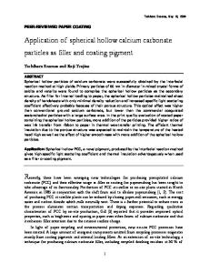
ligament thickness between the inclusions is small enough for these oriented lamellae to bridge between the particles ( : �m for HDPE, : �m for PA 6,6) this low shear resistance behaviour percolates throughout the structure and, while matrix yielding is a significant source of energy dissipation, toughness is enhanced (figure 1).
06
03
a
b
c
Figure 1: Preferential oriented lamellae: a) no bridging (brittle), b) bridging (tough), c) large deformation upon debonding; after Bartczak et al. [6] Effective toughening did not depend on the kind of filler used and was for both the rubber and hard filler modified systems controlled by the average critical ligament thickness, apparently being the single controlling parameter in the onset of toughening semi-crystalline polymers. Although the onset of toughening seems to be clear, there still was a striking difference in the level of toughness increase. In the study of Bartczak the specimens were prepared via injection moulding a long flexural bar, which was divided into two impact test specimens. For the calcium carbonate filled systems, the specimens from close to the injection gate showed an increase in impact properties that was twice as high as for the specimens from the far end. Furthermore, the relevance of debonding of the matrix from the particle was not experimentally proven. The goal of the present study was to investigate this difference between the observed level of toughness increase and to try and find a relation with the processing conditions. For this purpose similar materials and processing techniques were used, extended with a different surface treatment level of calcium carbonate and several extra processing conditions.
Experimental Materials and sample preparation The high-density polyethylene used in this study was Stamylan HDPE 9089s supplied by DSM, The Netherlands. It has a density of : g=cm2 and a melt flow index of dg=min (Mw = : g=mol; D= ). As a filler two types of precipitated calcium carbonate particles were used, Super-Pflex 100 and Super-Pflex 200, supplied by Specialty Minerals Inc., USA. Both types have an average particle diameter of 0.7 �m and only differ in level of stearic acid surface coating ( and ). Since the difference in results between the
0 963
8
1%
2
2%
70 000
5
HOME
two types of particles was very small, the level of surface treatment is not being discussed in detail in this study. Actually, we only like to mention that a surface treatment is necessary for complete dispersion of the particles, but too much surface treatment will increase the adhesion between polymer and particle, which according to the mechanism will have a negative influence on the impact properties. The latter was also observed in our study, because the impact results of the materials with Super-Pflex 100 (1% stearic acid) showed slightly higher values than the materials with Super-Pflex 200 (2% stearic acid).
5% 10% 15% 20% 25% 175 180
Different volume fractions ( = = = = ) of the calcium carbonate particles were mixed in the HDPE with a 25 mm Werner and Pfleiderer corotating twin-screw extruder, ZSK 25. The temperature of o C and the rotation speed of the screws was 150 rpm. The screw the extruder was in the range of configuration consisted of a melting zone, after which the calcium carbonate powder was fed to the polymer melt by a side feeder, and several kneading zones. The polymer pellets and the calcium carbonate powder were fed with the desired weight fractions by two K-Tron gravimetric material feeders. The extruded blends were pelletized and Izod impact bars were prepared.
160 160 3 500
First, compression moulded plates with a dimension of x x mm were made by melting the granular o C and a pressure of material in a mould in a hot press at kP a. The mould was rapidly cooled down to room temperature by placing it in a water cooled press. Izod bars with dimensions of x : x mm were cut out of the plates and notched with a notching machine, according to the dimensions of the ASTM D-256 protocol. Second, flexural test bars (ASTM D-790 x : x : mm) were moulded on a 35 ton o C and Arburg injection moulding machine. The injection moulding temperature of the material was o the mould was kept at C . Two Izod bars were cut out of the flexural bars, notched and marked as GATE and END, being respectively the sample cut out of the bar at the injection gate and the one at the end of the bar. In addition, for the blend containing calcium carbonate, some extra samples were manufactured with alternative injection moulding conditions, namely with the temperature of the mould at o C . Finally, plates with a dimension of x x mm were injection moulded with the same conditions as the flexural oC , T o C ). Izod bars were machined out of these plates in 2 directions; in flow bars (Tmelt mould direction and perpendicular to flow direction. These samples were marked accordingly as FLOW and PERP.
200
60 12 7 3
127 12 7 3 2
250
20
20%
= 250
60
70 70 3 = 20
Mechanical properties Impact tensile tests at a tensile speed of 1 m/s were performed at room temperature using a Zwick Rel hydraulic tensile machine. The impact energy was calculated by the integration of the measured forcedisplacement curve divided by the fracture surface area. For each blend composition and sample process condition, at least four specimens were tested. Crystalline orientation Wide-angle X-ray diffraction patterns were taken at the ID11 beamline at the European Synchrotron Radiation Facility (ESRF), Grenoble. 2-Dimensional patterns were recorded with a CCD camera with the X-ray beam going through the complete thickness of the sample. For a qualitative comparison of the crystalline orientation in the samples, the 110 and the 200 crystal plane of HDPE were isolated separately, and integrated in radial direction. To compensate for the different sample thicknesses and beam intensity, the obtained intensity vs. azimuth angle curves were normalized to the same surface area under these curves.
3
HOME
Results and Discussion Figure 2 shows the impact tensile test results as a function of blend composition for the compression moulded samples and for the GATE and END samples cut out of the flexural bars. An onset in toughness increase is seen at a volume concentration of approximately calcium carbonate, but the level of increase differs quite a lot for the different manufacturing conditions of the samples. First of all the toughness enhancement of the compression moulded samples is much lower than that of the injection moulded samples, indicating that if crystal orientation between the particles is the main concept in the toughening mechanism, it is not controlled by a heterogeneous nucleation of the polymer crystals on the particle surface.
5%
Impact energy (J/m2)
100 GATE END CM
80 60 40 20 0 0
5
10
15
20
25
30
CC (vol%)
%
Figure 2: Impact toughness of the HDPE-CC blends dependent on the volume of calcium carbonate (CC) and the type of specimen (GATE: gate side of injection moulded bar, END: end side of bar, CM: compression moulded
A much higher increase in toughness is reached for the injection moulded samples, but still a difference is observed for the GATE and END type of specimens. Hanging on to the concept of crystal orientation in the toughening mechanism, both the difference between the compression and injection moulding conditions as well as the difference between GATE and END type of specimens can be rationalized by the presence of flow induced crystal orientation [8]. Due to orientation of the chains in a polymer melt flow and upon solidification/crystallization of the polymer an oriented morphology is created as schematically shown in figure 3a. This crystal orientation is in the direction between the particles that is desired to reduce the plastic shear resistance in loading direction upon debonding of the particles (figure 3b).
4
HOME
Flow direction
a
b
Figure 3: Flow induced lamellae orientation: a) perpendicular to flow b) large deformation upon debonding
The level of toughness enhancement is now influenced by the amount of flow induced orientation, being absent in compression moulded samples and highest in the GATE part of injection moulded samples. This is shown in figure 4, which gives the normalized intensity of the recorded 2-dimensional 110 and 200 crystal plane patterns as a function of their azimuth angle. An unoriented crystalline morphology will result in horizontal line at a normalized intensity of 1, like the orientation plot of the compression moulded samples, which is expected to have an isotropic structure. A small degree of orientation is found for the END type of injection moulded specimens and the highest orientation exists in the GATE type of specimens. 2
110 200
1
0.5
0 0
a
90 180 270 Azimuth Angle [degrees]
360
1.5
1
0.5
0 0
b
90 180 270 Azimuth Angle [degrees]
360
110 200
FD
Normalized Intensity [−]
1.5
2
110 200
FD
Normalized Intensity [−]
Normalized Intensity [−]
2
1.5
1
0.5
0 0
c
90 180 270 Azimuth Angle [degrees]
360
Figure 4: Normalized intensity over the azimuth angle of the 110 and 200 crystal plane for a blend containing CC: compression moulded (a), injection moulded END type (b) and GATE type samples (c)
10%
20%
Table 1 gives the impact toughness results for the additional manufactured samples containing CC. The results observed are again related to the crystal orientation present in the samples. If the temperature of the mould is increased, cooling rate decreases, resulting in a lower flow induced crystal orientation due to the longer relaxation time of the polymer. For both the GATE and END type of injection moulded specimens a lower impact toughness is therefore found if the mould temperature is changed from o C to
20
5
HOME
60o C . The influence of cooling rate should also be taken into account when comparing the results of the injection moulded with the compression moulded specimens, because the cooling rate of the material during compression moulding is lower than during injection moulding due to the fact that the mould plates also have to be cooled.
Preparation
Type
Impact energy (kJ/m2) Tmould = 20 oC Tmould = 60 oC
Compression
CM
15
Injection bars
GATE END FLOW PERP
65 45 22 14
Sample
Injection plates
Table 1: Impact energy for the blend containing conditions
46 39
20% calcium carbonate for different processing
The difference found for the plate type specimens is also in accordance with the toughening mechanism of figure 3. If the loading direction of the impact test is changed from flow direction to the direction perpendicular to flow, the impact energy is decreased. Upon debonding of the particles, the interparticle ligaments have to undergo large shear deformation to obtain an increase in impact energy. The reduced shear resistance is present in one direction, namely the direction of the oriented chains, being the flow direction. In testing the injection moulded samples perpendicular to the flow direction, the required crystal orientation is not present, and toughness is not enhanced. The orientation in the injection moulded plates is obviously not very high, considering the difference between the GATE and FLOW type of specimens. If the we are able to test a specimen, with the amount of orientation as present in the GATE type of specimen, perpendicular to flow direction, we expect the impact toughness even to decrease below the value of neat HDPE.
Conclusions The results reported in this study show that the toughness of high-density polyethylene filled with calcium carbonate particles is highly influenced by the processing conditions of manufacturing the specimens. A large increase in toughness can be reached by the creation of a crystal oriented structure (e.g. via injection moulding) and choosing the proper loading direction. The earlier postulated toughening mechanism can still be accepted at least partly, considering the fact that an anisotropic crystal orientation between the particles reduces the shear resistance and allows large deformation and energy dissipation to take place. However, this anisotropic structure is merely created by flow induced crystal orientation and not by the presence of the particles themselves. However, we have to consider the possibility that the rheologic behaviour of the HDPE is changed with the addition of calcium carbonate particles and the rheology of the filled system should be investigated. Another problem is the complexity of understanding the injection moulding process and the final structure of an injection moulded sample. 6
HOME
References [1] S. Wu, Polymer,26 (1985) 1855 [2] S. Wu, J. Appl. Polym. Sci.,35 (1988) 549 [3] O.K. Muratoglu, A.S. Argon, R.E. Cohen, M. Weinberg, Polymer,36 (1995) 921 [4] O.K. Muratoglu, A.S. Argon, R.E. Cohen, Polymer,36 (1995) 2143 [5] Z. Bartczak, A.S. Argon, R.E. Cohen, M. Weinberg, Polymer,40 (1999) 2331 [6] Z. Bartczak, A.S. Argon, R.E. Cohen, M. Weinberg, Polymer,40 (1999) 2347 [7] Z. Bartczak, A.S. Argon, R.E. Cohen, T. Kowalewski, Polymer,40 (1999) 2367 [8] H. Zuidema, Ph.D. Thesis, Eindhoven University of Technology, (2000)
7