Timber Bridges Kjell Arne Malo
NTNU, Department of Structural Engineering
Wood as structural material • Strength: – Material strength: f ~ 20 to 40 MPa (tension – compression) – Structural strength: A*f, W*f. A and W are large.
• Stiffness: – Material stiffness: E ~ 12000 MPa – Structural stiffness: E*A, E*I. A and I are large.
• Dimensional changes: – Temperatur changes: 0.005 mm/(m and K) (40 % of steel) – Moisture changes: • Along grain: 0.1 mm / (m and %) • Normal grain: 2 mm / (m and %) 2
Norw. Univ. of Science & Tech.
Durability of Timber Structures?
Hopperstad Stave Church, Vik, Norway: Built 1130 Kjell A. Malo,
[email protected]
Background – durable timber bridges
• Future:
• Norway: – – – –
16 000 existing bridges 400 in planning/construction 300 timber bridges after 1996 Timber bridges: • Crossing of roads and rivers • Full traffic load or pedestrian • Wood: 1000 m3 / bridge ?
– Existing bridges need replacement or renovation – Less maintenance costs – Less environmental costs – Minimum closing time – Most spans: 10 – 120 m – Considerable market potential for timber bridges
Department of Structural Engineering Norwegian University of Science & Technology
4
Today • Fretheim bridge (Flåm): – Copper cladding on the top faces – Ventilated venetian blinds – side faces – Preservatives Fretheim bridge, Flåm, Norway, (photo: SWECO)
• General durability issues: – – – –
Keep water out of wooden material (moisture content < 18-20%) Suspectible points: upward surfaces, cracks, around details, in connections Free end grains: Rapid transport of liquid water Covered
Department of Structural Engineering Norwegian University of Science & Technology
5
Environmental friendliness • 1 kg wood stores about 1.6 - 1.8 kg CO2 • 1 m3 wood stores in Spruce 700 kg CO2 (810 kg Pine) • Only relevant building material with positive CO2 impact • Poisonous preservatives –> environmental friendly? • Creosote stop in 2018? • Less reliance in preservatives Dep. Structural engineering
6
Kjell A. Malo
Background: Durable timber bridges
Tynset bridge, Norway (photo: K. A. Malo)
• To-day: – – – – – –
• Future - timber bridges ?
Free span < 80 m Many connections Preservatives Wood or concrete deck Labor - Wood consumption? No tool for evaluation of durability
– – – – – –
Most span. 10 – 150 m ? No toxic preservatives? Life time: > 100 years Low maintenance costs Documented environmental impact Quick installation on site
Department of Structural Engineering Norwegian University of Science & Technology
7
International project initiative: • Project name: – Durable Timber Bridges (DuraTB)
• Financing (Budget ~ 17 mill NOK): – ERA-NET+ EU FP7 Wood Wisdom call 2013 – Partners – Sponsors
• Participating countries: – – – –
Norway Sweden Finland USA Kjell Arne Malo
8
Norw. Univ. of Science & Tech.
20 Partners: • Norway: – NTNU, SVV (NPRA), Moelven Limtre AS
• Sweden: – Lund University, SP, Svenska Trafikverket, Moelven Töreboda AB, Martinsons Träbroar AB, Limträteknik AB
• Finland: – VTT, Aalto University, Finnish Transport Agency, RT (Finnish construction industry), Finnish Wood Research, Versowood OY, Late-Rakenteet OY, Metsäwood OY, City of Espoo, City of Helsinki
• USA – Forest Products Laboratory (US federal goverment body) Kjell Arne Malo
9
Norw. Univ. of Science & Tech.
DuraTB: Overall objective of the project:
To develop durable timber bridges with a given estimated technical lifetime.
Dep. Structural engineering
10
Kjell A. Malo
Durable timber bridges
Department of Structural Engineering Norwegian University of Science & Technology
11
Scientific and technological objectives: • • • • • • • •
To develop an exposure model related to risk of decay validated for a given set of timber bridges. To develop a performance model relating microclimate representative for wooden bridge elements to the risk of their decay To develop a methodology to account for uncertainties in service life design of timber bridges To develop a set of design concepts for durable timber bridges in the span 10 – 150 m. To develop splicing technology for massive block-glued glulam crosssections for bridges. To improve the performance of stress-laminated wooden deck and details of wooden deck-plates. To develop fatigue strength criteria for axial threaded rod (screw) connectors. To develop design integrated maintenance concepts for timber bridges. Kjell Arne Malo
12
Norw. Univ. of Science & Tech.
DuraTB (coordinator: NTNU) WP 1
Task 1.1
2 2.1 2.2 2.3 2.4 2.5 3 3.1 3.2 4 4.1 4.2 4.3 4.4 4.5 4.6 4.7 5 5.1 5.2 5.3 5.4
Coordination Project management Performance based service life design of timber bridges Collection of field data from existing instrumented bridges Development of climate exposure model for bridge structures Tests of climate exposure (moisture content, temperature) in structural details Development of suitable dose-response model for fungal decay Methodology for service life design of bridges Hygro-thermal effects in wooden members Numerical models (FEM) relating rain, spray, RH, T, to distribute material climate effects in members Moisture distribution, moisture induced stress and risk of cracking in members and connections Design concepts for durable timber bridges Wooden bridge decks Design concepts for short to medium span bridges Design concepts for medium to long span bridges Splicing of large glulam members Fatigue of axial-carrying connectors in wooden members Performance evaluation of design concepts (structural performance, lifetime, LCC, LCA) Maintenance practices and repair techniques for extending service life of timber bridges. Dissemination Produce a book or report on design of durable timber bridges Arrange open workshops Prepare proposals to CEN TC 250 SC5 to the new generation of EN 1995-2 Timber bridges Publication scientific papers, journals and conferences
Kjell Arne Malo
13
Norw. Univ. of Science & Tech.
Durable Timber Bridges DESIGN concepts • Design without moisture traps – No connections on exposed top and side faces – Abutment and supports – Pre-stressed timber decks
• Network arch: – – – –
Span. 50 – 200 m Wooden arch and deck Steel hangers Wood consumption: • •
•
Inrease, due to few connections Decrease, due to network arch concept
Girder-deck-plates composites (10 – 30 m): – Wood or concrete deck – Timber girders
Dep. Structural engineering Norw. Univ. of Science & Tech
14
Kjell A. Malo,
[email protected]
Arch bridges
Different types of arch bridges
• Bridge part prefabrication limitations: – Transport – Chemical treatment – Max. Element length 30-35m
Department of Structural Engineering Norwegian University of Science & Technology
15
Arch bridges
Tynset bridge, Norway (photo: K. Bell)
• Truss-work type arches: – Use of truss connections as mounting connection – Connections in truss exposed to axial forces
• Bridges with vertical hangers: – Vertical hangers – point load in the arch – Large moment action in the arch Department of Structural Engineering Norwegian University of Science & Technology
16
Sideway stability • Issues – Slender arch ⟹ need sideway support – Connection at support ⟹ clamped ? – Wind bracing at the top of arches ⟹ force transfer to the support (Tynset bridge – no horizontal forces transfer from arch to the deck) – Small spans ⟹ prestressed decks carry horisontal forces – Small spans ⟹ hangers replaced by rigid portal frames; increased transverse stability
Footbridge, Tromsø, Norway (photo: SWECO) Department of Structural Engineering Norwegian University of Science & Technology
17
Massive arch bridges – Inclined hangers
Inclined hangers
• Traffic loading: – Heavy loading in skew position – Vertical hangers: loading as point loads; results in large moments in arch – Remedies: ‘network arch bridge’ with inclined hangers; moment action reduction: roughly one quarter vertical displacement reduction: nearly one sixth
Department of Structural Engineering Norwegian University of Science & Technology
18
Stability of network arch
The two lowermost buckling modes for an arch; hangers in one plane
Network arch with double hangers in spoked wheel configuration Department of Structural Engineering Norwegian University of Science & Technology
19
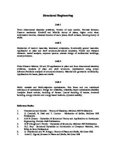
Stability of network arch
(𝐿 + 𝛿𝐿)2 = 𝑎2 + 𝑅2 + 2𝑎𝑅 sin 𝛼
Fig. Lateral stiffness from spoked wheel configuration
Where: 𝐿 – length of hangers 𝛿𝐿 – elongation 𝑎 – half distance of hangers 𝑎 𝑎 𝑎 fastening points – angle of rotation 𝑅 – radius of rotation
𝜀=
2𝑎𝑅 1+ 2 sin(𝛼) − 1 𝑎 + 𝑅2 𝑟
𝜀 = 𝑟 2 +1
Fig. Strain in hanger
Where: 𝑟 = 𝑎/𝑅 – geometric ratio
Department of Structural Engineering Norwegian University of Science & Technology
20
Bridge with spoked hangers – concept study • Conceptual design – – – –
Combination of network arch and light-weight deck in long timber bridge concept Network arch with inclined hangers Numerical analysis (full and scaled) and experimental model (scale 1:10) Eurocode requirements
• Design requirements – – – – –
Free span of 100m 2 lines of road traffic Width 10m Glulam circular arches Inclined network hangers
Anna W. Ostrycharczyk
– – – –
Spoked hangers configuration Tension tie No wind truss between arches Timber stress laminated deck
Department of Structural Engineering Norwegian University of Science & Technology
21
Scaled laboratory model
Experimental model in scale 1:10
Department of Structural Engineering Norwegian University of Science & Technology
22
Scaled laboratory model
Support conditions; hinged in the plane of the arch, transversely rigid
Department of Structural Engineering Norwegian University of Science & Technology
23
Scaled laboratory model
Fastening of hangers to the wooden arch
Anna W. Ostrycharczyk
Department of Structural Engineering Norwegian University of Science & Technology
24
Structural behaviour of the bridge • Parameters for evaluation – – – – –
Stiffness Mass distribution Eigenfrequencies and vibrational modes Acceleration levels Damping characteristics
• Scaled model of the deck – – – –
Amount of wood material in the timber deck is roughly twice of that in the arches Measured self weight - 560 kg Stress-laminated deck height is 98 mm Pre-stressed to nominal stress of 1.0 MPa
Department of Structural Engineering Norwegian University of Science & Technology
25
Dymanic behaviour of the deck
Measured vibrational modes in vertical direction, experimental model of timber deck
Numerically obtained vibrational modes in vertical direction of timber deck
Department of Structural Engineering Norwegian University of Science & Technology
26
Dymanic behaviour of the deck
Measured damping, modes and frequencies compared to numerically obtained frequencies
Mode
Measured frequency [Hz]
Numerical frequency [Hz]
Measured damping [%]
Vertical 1
3.0
3.2
4.2
Vertical 2
8.0
7.5
0.63
Vertical 3
17.5
16.9
0.95
Horizontal 1
17.8
18.2
2.4
• Comment – stress-laminated deck behaves like a massive wooden block ⟹ pre-stressing is sufficient
Department of Structural Engineering Norwegian University of Science & Technology
27
Vertical vibrations of the deck
Mode shapes with deck vibrating in vertical direction
M o d e
Experimental model scale (1:10) Frequency [Hz]
Numerical model scale (1:10) Frequency [Hz]
Numerical model full scale (1:1) Frequency [Hz]
1
none
26,5
2,95
2
28,5
24,7
2,27
3
43,5
42,2
3,99
Department of Structural Engineering Norwegian University of Science & Technology
28
Horizontal vibrations of the deck Mode shapes with vibrations mainly in horizontal Mode direction
Numerical model scale 1:10 Frequency [Hz]
Numerical model full scale(1:1) Frequency [Hz]
1
15.9
1.98
1a
8.66
0.809
1b
9.29
0.814
Horizontal deck impact Measured experimental model 1:10 ; Frequency: 15.9 – 16.4 [Hz]
Department of Structural Engineering Norwegian University of Science & Technology
29
Conclusive remarks • Network arch bridges are – Competitive – Very stiff in the plane of the arches – It is possible to use this concept to build long bridges without the need for truss-work for wind forces or stability, by using hangers in a spoked configuration – Reduction of moment action in arches due to better load distribution
• Acknowledgements – This work has been made possible by a project grant gratefully received from The Research Council of Norway (208052) and financial and technical support from The Association of Norwegian Glulam Producers, Skogtiltaksfondet and Norwegian Public Road Authorities.
Department of Structural Engineering Norwegian University of Science & Technology
30