Manufacturing - Engineering
THE REFLUX MILL AND THE REFLUX MILLING PROCESS T. M. Hamill A. & W. Smith & Co Ltd Bromley BR2-9NA, Great Britain
ABSTRACT, The reflux mill is a light duty mill suitable for extracting juice from bagasse of very high juice t o fibre ratio. ltois capable only of extracting juice and causes little or no rupturing of plant cells. The reflux mill can achieve an extraction efficiency equivalent t o that of a standard 3-roller mill, if supplied with sufficiently wet bagasse in which the percentage of ruptured plant cells is high. The power required to drive a reflux mill is approximately 1 tenth of that needed for a standard 3-roller mill. If located in a milling tandem, the reflux mill can be chain driven from a conventional mill. Space requirements are equal to that of a normal apron carrier. First cost is l o w compared to that of a conventional mill. The reflux milling process is one which incorporates the wet milling of bagasse by a reflux mill situated in a conventional tandem of 3-roller mills. The required wetness for suitable operation is produced automatically. If suitably prepared cane is supplied to such a tandem, the reflux mill will produce an increase in tandem extraction equivalent t o that which would occur with the addition of 1 supplementary 3-roller mill. INTRODUCTION
Early ex@eriments New techniques have recently been introduced for extracting sugar juice from sugarcane. These techniques utilize a series of countercurrent washings to extract sugar juice from cane which has been prepared initially by shredding in a separate machine'. After washing, the spent cane (bagasse) is dried in conventional 3-roller sugar mills, or in especially designed presses. I n view of these techniques, laboratory work was initiated to determine what gains, if any, could be expected, if such washing were carried out in a countercurrent manner in the intermediate carriers of a conventional tandem. Results from these experiments indicated some improvement in extraction. However, the milling characteristics of the extremely wet bagasse leaving the washing section were undesirable. Grinding rates of the laboratory apparatus were greatly reduced. I t was believed that capacities could be restored by squeezing the bagasse leaving the washing section, using light pressure squeeze rollers. This would have the effect of reducing the bagasse to a juice content more normal for milling. There light pressure squeeze rollers not only made the bagasse acceptable for milling, but also increased the efficiency of the washing section considerably. The work described was carried out in 2 roller batch mills which were hand operated. I n order to test the process further, a continuous motor driven
I
T. M. HAMILL
tandem was constructed and erected in the laboratory. This permitted the measurement of the power required for both the regular 3-roller mills and the light pressure squeeze rollers so that a comparison could be made. I t also permitted experimenting with feed angles, squeeze roller pressure, and the proper surfacing needed for the squeeze rollers. I n the initial tests, 2 light pressure mills were placed between the first and second standard mills, and the juice from the second standard mill was refluxed over the 2 light mills in counter-current manner. The juice expressed by first light mill in the tandem was then mixed with that expressed from the first standard mill (crusher), as in normal practice. The extraction of the tandem, in such an instance, was increased by an amount almost equivalent to that which would have been expected if 2 additional standard 3-roller mills had been added. A diagram of the tandem arrangement for this test is shown in Fig. 2.
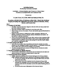
FIGURE 1. LABORATORY MILLING TANDEM Feed box on left followed by three roller mill, two reflux mills, and three three-roller mills. First mill juice tank and wet milling juice tank at left. Maceration pumps and sumps on floor. Water tank with submersible pump and head tank at lower right.
An additional test was run with the 2 light pressure squeeze mills installed in front of the tandem. Almost identical results were obtained. I n this instance, the entire tandem was run "wet". No dry milling was performed. I n both instances mentioned, the cane supplied was extremely well prepared. The first of these tests gave rise to the conclusion that 2 such light pressure
1710
MANUFACTURING
- ENGINEERING Water
Cane,
Retlux Mills
~ i x e Juice d
'
FIGURE 2.
squeeze mills would enhance the extraction of a given tandem almost equal to the addition of 2 conventional mills. The second led to the inference that a series of such light mills could accomplish the normal extraction process if followed by conventional mills to finally dry the bagasse to an acceptable moisture. I n both instances good cane preparation would be required. Further tests indicated that bagasse of a dryness sufficient for acceptance by a standard mill could be attained with a power supply to the light mills of about 10 per cent of that required for a standard mill. At such a power input, the juice-fibre ratio of the feed bagasse to the light mills would be sufficiently high for efficient operation. These light pressure mills operate in much the same manner as standard mills, except that they perform best when fed with extremely wet bagasse. However, since they perform no grinding or attrition action, they have been termed 'reflux mills'. The term reflux milling has been given to describe the process with which they are associated. EQUIPMENT EMPLOYED FOR FULL SCALE TESTING
Following the initial laboratory work, a partnership was formed between an American company and A. & W. Smith & Co Ltd of Great Britain in order to investigate the practicality of the reflux mill in full-scale operation. Two full sized reflux mills were manufactured in 1971. With the kind permission of the management of Belize Sugar Industries Ltd, these mills were installed in their Tower Hill factory in British Honduras prior to the 1972 crop. These 2 reflux mills were 2 134 mm wide and were integrally designed to take the place of the apron carrier between the first and second mills in their 2 134 mm 12-roller tandem. The reflux mills were provided with a scraper of conventional type to lift the bagasse from the discharge roll of the first 3-roller mill. The bagasse was then fed over a drain plate to the first reflux mill. Assistance to feeding was supplied by 2 feeder rollers which were surfaced with herringbone type tines. Bagasse from the first reflux mill was then fed without further assistance to the second reflux mill. Because of the centre distances between2:tbe 2 standard 3-roller mills in this particular tandem, bagasse from the second reflux mill was fed to the second standard mill by means of a short slat-type apron carrier.
T. M. HAMILL
1711
Driving power for the 2 reflux mills was provided by heavy roller chains from the first standard mill. Power for the feeder rollers was provided by chains from the reflux mills. The discharge apron carrier was driven from the second standard mill through an air operated clutch. The entire reflux mill assembly was mounted on the stringer bedplate of the standard tandem, and could be removed integrally by the millroom crane. The top rollers of both reflux mills were of tubular construction and were surfaced with 19 mm square parallel steel bars spaced circumferentially about 100 mm apart on the roller face. Originally, the lower rollers were surfaced with 8 mm thick perforated plate having a 16 mm square perforation. This plate was rolled to the same diameter as the roller and was welded to the face. Although this surfacing provided adequate grip for satisfactory feed, it failed due to fatigue and had to be removed after processing some 230 000 tons of cane. Subsequent surfacing of the lower rollers was provided by bars similar to those on the top rollers with the exception that the'"circumferentia1 spacing was reduced to approximately 56 mm centres. Juice from the second standard mill was discharged to a tank and pumped to a weir type macerating device in front of the second reflux mill by a Scott Wemco chokeless pump. Juice from the second reflux mill was then pumped by a similar pump to a weir type macerator in front of the first reflux mill.
I
FIGURE 3. Shop photograph illustrates integral design of machine. Herringbone feed rollers are at left and are followed by two two-roller reflux mills.
MANUFACTURING
- ENGINEERING
Drainage for the large quantities of juice involved was provided by means of special drainage plates in front of each reflux mill. Originally these drainage plates were provided with approximately 0,258 square metres of drainage area. This drainage area was subsequently doubled (see photograph).
FIGURE 4. Feed plate for reflux mill showing large drainage area.
One of the features of this particular reflux mill assembly was that it was capable of operating solely as an intermediate carrier, thus allowing the tandem to be tested under conventional milling operation as well as under reflux milling conditions. Tests were carried out on this installation during both the 1972 and 1973 crops.
FIGURE 5. Hydraulic controls for two reflux mills. EXPERIMENTAL PROCEDURE
Tandem testing during the 1972 crop involved the use of the standard direct method for calculating tandem extraction. Cane deliveries were made by truck and each load of cane was weighed and delivered to the cane yard where it was either stored in bulk or in bundles with slings attached. Under ideal conditions, all cane so stored was "ground out" by 6.00 AM each morning. Mixed juice was weighed and sampled continuously. Imbibition water was weighed continuously and wash water was metered. First expressed juice was sampled continuously and last roller juice and bagasse were batch sampled in the usual manner. Bagasse moisture determinations were carried out in a
1713
T. M. HAMILL
Dietert moisture teller. Pol per cent bagasse was determined in the normal manner with a Norris digester. Brix readings were done by refractometer and a standard sugar saccharimeter was used. Although such a method of analysis is quite standard and commonly employed in reporting the extraction of a tandem, it presents some drawbacks when it is desired to find the maximum capabilities of a certain machine. The shortest reporting time was obviously one day, so that any results reflected the differences in performance of various shift personnel. I n addition, cane was not always "ground out" by the end of each daily accounting period, and the weight remaining in the yard was estimated. If the weight remaining in the yard was small, the possible error in the extraction figures was small and negligible, but if it was large the results of a day's run were unduly affected. I n addition, any irregularity in mill operation tended to void a day's result, making evaluation of the reflux mills difficult. I n 1973, an additional series of tests was arranged in order to eliminate some of the previous objections. These arrangements provided for a one hour test of tandem with and without the reflux mills in operation. The test method employed the so-called inferential method, and involved the continuous sampling for one hour of prepared cane, continuous weighing and sampling of mixed juice, and continuous sampling of bagasse and last roller juice. Weights of imbibition and wash water were also recorded for check purposes. Representative cane sampling has always been a problem associated with this method of testing. However, the cane knife installation a t Tower Hill was situated at the discharge nose of the feeder carrier, and cut cane was discharged almost vertically downwards onto the main carrier. I t was, therefore, possible to insert a sample box into the flow of cane and obtain what appeared to be a representative sample. Cane so collected in the,box was stored in 68 litre plastic bags. Two 68 litre bagfuls of cane were usually collected for each hour test. These bags were taken to the laboratory where any large pieces were reduced in size with pruning shears. The cane was then sub-sampled. A commercial Waring blender was used for disintegration of cane and bagasse. Pol and brix were obtained from the blender extract. The disintegrated fibre in the blender was then washed, dried and weighed, giving a direct fibre determination. Dietert type driers were used in all cases. RESULTS
The 2 reflux mills were put into operation a t the start of the 1972 crop at Tower Hill. Feeding characteristics were good and the mills were able to handle extremely wet bagasse. However, the original drainage plates located a t the entrance to each mill were inadequate. At the same time, the drainage tank beneath the second reflux mill choked with cush-cush. This tank fed the Scott-Wemco pump supplying maceration to the first reflux mill. A new tank was supplied, and the area through the drain plates was increased to about 0,258 m2. These alterations proved helpful, although insufficient for desired operation. Test results indicated improvement in extraction but fell short of those obtained in the laboratory experiments. Fig. 6 shows the results obtained by the tandem operating with the reflux mills as compared with the best results obtained for the 1971 and 1972 crops without the benefit of the reflux mills.
1714
MANUFACTURING - ENGINEERING
Q Reflux Milling 63,5 mm Min Setting 13 600 kg Load
do do 5 700 kg Load do 140 mm M i n Setting No Load X Corrected Reading
A -t
0J 160
I
I
i
180
200
220
I
I
I
240 260 280 Imbibition Percent Fibre
I
I
1
300
320
340
FIGURE 6.
On April 10, 1972 the surfacing of the lower roller of the second reflux mill failed. The cause was determined to be fatigue failure. This failure was repaired by welding but 3 days later the surfacing of the lower roller of the first reflux mill failed in the same manner and was also repaired by welding. However, the failures in the surfacing had become so numerous by this time that pressure on the rollers was reduced to zero, and tests were discontinued. At this date, the reflux mills had handled 117 000 tons of cane. The mills continued in operation until April 30 when they were removed due to a broken foundation bolt. They had then handled 230 000 tons of cane. I n view of the promising extraction results obtained, it was proposed to revise the drainage system and continue testing during the 1973 crop. Drainage plates of a radically different design were produced which gave 100% increase in free area on approximately 0,516m2. I n addition, new bottom rollers were provided which incorporated drainage grooves. Other than this, no basic changes were made to the mills. At start-up in December 1972, it was immediately noticed that the original feeder roller arrangement for feeding bagasse from the first regular mill was no longer operating satisfactorily. Feed bagasse would choke between the new drainage plate and the second small diameter feeder roller. Efforts were made to operate without this second feeder roller. However, the feed geometry of the bagasse entering the first reflux mill was such that no pressure could be applied to the mill. Various changes were made to the feeder roller arrangement in an effort to overcome this feeding problem in front of the first reflux mill, but these efforts were unsuccessful^ However, the first reflux mill would accept feed if the feed opening was set a t its widest setting. At such an opening, this mill acted as a satisfactory feeder to the second reflux mill, which then operated satisfactorily. I n view of these difficulties, it was decided to carry out tests on the Tower Hill tandem using only the second reflux mill while utilising the first as a
1715
T. M. HAMILL
feeder to the second and modifications to the juice piping were accordingly made. The maceration distribution tank in front of the first reflux mill was retained only as a holding tank in order to give a visual indication of the juice flow from the second reflux mill. Extraction results for the tandem, using only a single reflux mill are shown in Fig. 7. Also shown for comparison are the best results for this tandem while operating in the normal fashion during the 1971 and 1972 crops without the aid of the reflux mill.
13
18 Apr 73 y Best Results Normal Milling 1971 and
I
t 29 Mar 73 (Solid Feed Platel
r
-
Single Reflux Mill 1973
Normal Milling Tests 1973 ~ e f l u xMilling Tests 1973
0 +
0 160
I
I
I
I
I
I
I
t
I
180
200
220
240
260
280
300
320
340
Imbibition Percent Fibre FIGURE 7.
Several tests were also run on the tandem without the reflux mill in operation in order to show the correlation between the methods of analysis. These results are also shown in Fig. 7. The curve showing the best results for 1971 and 1972 were made by the "direct method" of analysis. There is reasonable correlation between this curve and the tests done by "the indirect method". Tabulated results for the preceding tests are given in Table 1. CONCLUSION
Tests a t the Tower Hill Factory indicate that a single reflux mill, when operated properly, can reduce milling losses by approximately 27 per cent. I t is estimated that 2 such reflux mills would have reduced losses by as much as 40 per cent. DISCUSSION
The tests at Tower Hill were conducted at a more or less constant milling rate in order to show what gain in tandem extraction might be attained. However, it can be readily hypothecated that the use of the reflux mill also could have permitted a considerable increase in milling rate without reduction in normal milling efficiency. Increasing the grinding rate without loss of efficiency may be more important commercially than merely gaining in extraction at a fixed rate.
TABLE 1.
1
Cane Date
Operation
Mar 26 Reflux Mill
tons per hour 85,92
pol %
fibre
Baeasse " moisture
%
(
%
Mixed juice tons per hour
Imbibition tons per Imbibition Extraction hour % fibre % pol
pol %
fibre %
2,60
48,40
48,24
108,8
46,72
401,O
94,59
I
3,26
46,40
49,46
136,3
44,79
272,O
93,53
2
2,35
47,30
49,14
112,6
30,49
218,O
94,96
3
3,226
48,OO
47,70
105,l
25,41
192,O
93,98
4
2,77
47,lO
49,28
108,2
473
202,O
94,79
13,48
13,56
Mar 29 Reflux Mill
127,O
14,09
12,98
April5 RefluxMill
111,9
12,31
12,49
April7 RefluxMill
107,3
13,93
12,35
April 7 Reflux Mill
109,7
13,93
12,35
April 18 Normal Mill
113,8
13,35
13,20
3,56
42,50
53,ll
113,8
35,39
235,o-
91,72
April 19 Normal Mill
102,8
13,47
13,92
2,94
44,40
51,89
103,4
32,91
230,O
93,16
April 21 Normal Mill
111,2
13,11
12,75
3,49
45,60
49,75
118,2
37,95
269,O
92,55
1
1
/
1
1
I
NOTES: 1. 2. 3. 4.
Notes
9
8 d
2 !
Bar type feed plate. Solid emergency feed plate. Slotted emergency feed plate. Slotted emergency feed plate and reflux pump choke for f 5 minutes.
0
I
M
2
0
I
I t is obvious that cane preparation is important in the successful use of the reflux mill. At Tower Hill, preparation was about 70% as determined by simple "bottle test". During these tests only a single set of cane knives was employed. These were of standard A. & W. Smith design. The knives were closely spaced, and every other blade was of the blunt type with a square end. The balance were of the conventional sharp rotatable type. Knife maintenance was carried out weekly, but it is probable that preparation deteriorated at times. Any increase in cane preparation, either by double knifing or by shredding, would increase the results of the reflux mill more or less in proportion to the increase in preparation. Operating difficulties during the 1973 crop indicate the need for top and bottom feeder rollers in front of the reflux mills. The high area drainage plates employed have sufficient frictional resistance to render conventional feeder rollers unsuitable. The bottom rollers of the reflux mills should be provided with juice grboves that can be scraped clean by the discharge scrapers. I n addition, the surfacing of the bottom rollers should be altered so that there will be less tendency for tramp iron to become trapped in the gripping surface. The perforated metal surfacing employed during the 1972 crop presented no problem in this respect. Considerable difficulty was experienced with the Scott-Wemco chokeless pumps employed in conjunction with the reflux mills. The size and amount of trash in the juice from the second regular mill of the tandem was considerably larger than anticipated. Although shaped entrance pieces were prepared and fitted to the pumps, choking occurred regularly, and it was necessary to employ a pump tender during the test to keep the pumps clear and continuously operative. I t was noticed that a pump entrance of the size of the mixed juice pumps (250 mm diameter) was much more appropriate, and this should be considered in the future. The variable speed belt drives provided with the reflux pumps were of a type unsuited to the wet conditions surrounding a milling tandem. I n future these should be replaced by a type with an operating mechanism suitably protected from rusting.
EL MOLINO DE REFLUJO Y PROCESO DE MOLIENDA T. M. Hamill RESUMEN El molino de reflujo es un molino de construccidn liviana adecuado para extraer jugo del bagazo de una razdn alta de jugo a fibra. Es cape2 de extraer jug0 solamente y causar poca o ninguna rotura a las cklulas de la planta. El molino de reflujo puede alcanzar una eficiencia de extraccidn equivalente a la de un molino standard de tres mazas si es alimentado con suficiente bagazo h~jmedoen el cual el porcentaje de cklulas rotas es alto. La potencia requerida para accionar un molino de reflujo es aproximadamente una decima parte de la requerida por un molino standard de tres rodillos. Si el molino de reflujo es instalado en un tandem el mismo puede ser accionado por medio de cadena desde un molino convencional. Los requerimientos de espacio son iguales a 10s de un conductor intermedio del tip0 de tablillas.
1718
MANUFACTURING
- ENGINEERING
El costo inicial es bajo comparado con el de un molino convencional. El proceso de molienda de reflujo es aquel que incorpora la molienda de un molino de reflujo localizado en un tandem convencional de molinos de tres rodillos. La humedad requerida para la correcta operaci6n se produce automi3ticamente. Si al tandem se le suple con caiia debidamente preparada el molino de reflujo producird un aumento en extraccidn equivalente a la que se pudiera obtener con la adici6n de un molino de tres rodillos.