PHILlPS
370
TECHNICAL
REVIEW
VOLUME
29
The Philip,s. electron microscope EM 300 e. J. Rakels, Le. Tiemeijet and K. W. Witteveen
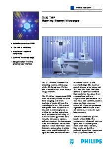
Two parallellines of attack can be distinguished in the development of the Philips electron microscopes. Improvement of the resolving power goes hand in hand with improvement of the arrangement and design of the instrument, giving maximum efficiency of operation and ease of use. The latest Philips electron microscope, the EM 300, offers some noteworthy . advances in both of these aspecis.
Introduetion
The range of electron microscopes put on the market by Philips in the last 20 years, the EM 100, the EM 75 and the EM 200 [1], has recently been extended by the addition of a new instrument, the EM 300. The main difference between this microscope and the others is its even better resolving power (less than 5 A). The EM 300 is also simpler to operate than its predecessors, and in its equipment ánd design even more attention than before has been paid, Jo the convenience of the user. A large number of matching accessories have been developed; so that the microscope can be used for a very wjC!~variety ·of investigations without requiring major changes ofthe instrument. The picture can be displayed oil'a1elevisio~ mbnito;.[2] as well as on the usual fluorescent 'screen. The magnification can be varied in 31 calibrated steps from 220 tirnes to 500 000 times; the range of possible magnifications thus partly overlaps that of the optical, microscope. , As ~ can be seen from .fig. 1, the. microscope tube ofthe new instrument is vertical, .as-it is jn the EM 200 and the'EM 75. This arrangement has proved to be the best one for stability, ready accessibility of the operating controls, easy attachment of accessories and simple maintenance. The cabinet on the left-hand side contains the sensitive electronic circuits, such as the stabilizing circuit>f;r the' high voltage and' the lens currents, and various auxiliary circuits. The vacuum system is accornmodated in ~!1Ccentral 'section, behind the space for the-operator'sfèet. This 'central section, which carries the' microscope tube, is very .sturdily built. to ensure mechanical stability, and its.weight is taken directly by the floor, independently of the two side cabinets:
..
Ir. C. J. Rakels, J. C. Tiemeijer and Ir. K. W. Witteveen are with the Philips Industrial Equipment Division (PIT), Eindhoven ..
In the projection chamber, fitted with three viewing windows, the fluorescent screen is located at the height of the table-top. This screen can be swung aside to give the electrons access to a plate camera or to a television camera tube ("Plumbicon" [*1 tube). When the camera tube is used, an image intensifier can be interposed. Facilities are also available for taking photographs with two types of roll film camera in addition to the plate camera. The electronic circuits are all transistor circuits. Some of them are water-cooled. All circuits are contained in standard exchangeable modules. The operating controls not regularly needed are on sliding panels immediately below the table-top (fig. 2). There are no controls on the table-top itself. One of the distinguishing features of the vacuum system is that it works automatically, and another is that the roughing pump can be switched off for hours once a sufficiently high vacuum has been reached. This eliminates a major source of vibration and noise. The vacuum is better and is reached more quickly than in the predecessors of the EM 300. A number of vacuum locks are provided, so that the filament, photographic plates or films and the specimen can be changed without having to admit air into the entire microscope tube. Photographic exposures are also very easy to make. The film and plate transport is motor-driven, and the EM 300 is fitted with an exposure meter which is arranged so that photographs may be taken in much the same way as with a semi-automatic camera: for correct [*] [1]
[2]
Registered Trade Mark for television camera tubes. A description of the EM 100 electron microscope is given in: A. C. van Dorsten, H. Nieuwdorp and A. Verhoeff, Philips tech. Rev. 12, 33, 1950/51, and of the EM 75 in A. C. van Dorsten and J. B. Le Poole, Philips tech. Rev.17, 47, 1955/56. See P. H. Broerse, A. C. van Dorsten and H. F. Premsela, Philips tech. Rev. 29, 294, 1968 (No. 10).
1968, No. 12
ELECTRON
Fig. I. The Philips
MICROSCOPE
EM 300
EM 300 electron
microscope.
371
372
PHILlPS
TECHNICAL
REVIEW
VOLUME
29
Fig. 2. The operating controls. that are most frequently needed are within easy reach above the table-top; the others are on sliding panels immediately below it.
factors that deterrnine the resolving power are dealt with. The other sections will be concerned with technical features of the microscope and accessories. Electron optics and resolving power Fig. 4a shows schematically the principal electronopticai corn ponents inside the microscope tube. Apart from various diaphragms, these components (from
exposure the operator adjusts the shutter speed or current density on the screen until the pointer of a meter on the control panel is at the centre of the scale. To make an ordinary exposure and a diffraction exposure of the same object one after the other, it is simply necessary to turn the knob of the "function switch". A n im portant feature of the new microscope is that all parts of the electron-optical system can be separately aligned. This minimizes displacement of the image in the image plane, due say to variations in the strength of the lenses. The very high resolving power of the new microscope is illustrated by fig. 3. It is so good partly because of tbe mechanical stability noted earlier and partly because of the excellent stabilization of lens currents and high voltage, the low sensitivity to external fields and, in particular, the extremely short focal length of the objective lens (1.6 mm). The importance of making the focal length short is explained in the next section, where the image formation and the electron-optical
Fig. 3. Two photomicrographs of the sarne specimen in which details situated 5 A apart can be distinguished. The fact that the sarne features are seen on both exposures proves that they are not grains from the photographic emulsion.
1968, No. 12
G[UJ
ELECTRON
EM 300
373
r
-ea,
C21i-IlD2
MICROSCOPE
0
0
Di
Di
'I'Sp
1
,Sp
0---
- -03
- -04
Di
I I
[--
+
I
I
O~~~
Dill""m-D4
ImD
Pr
Pr
Pr
prll.m 'I , 1 , 1 , 1 , 1 1 1
,,
S-'---'Q
12.
s.
Fig. 4. a) Schematic arrangement ofthe microscope tube. G emission chamber with electron gun. Cl first condenser lens. C2 second condenser lens. 0 objective lens. Sp specimen. Di diffraction lens. I intermediate lens. Pr projector lens. S fluorescent screen. Dl and D2 condenser diaphragms. De objective diaphragm. D4 selector diaphragm. b) Path ofrays in normal use (high magnifications). The intermediate lens and the diffraction lens are both in operation. c) Path of rays for medium magnifications. The objective lens forms a virtual image of the object. The intermediate lens is switched off. . d) The diffraction lens used as objective (very small magnifications, for initial investigation ofa specimen). In the case illustrated the objective lens is weakly excited. e) Electron diffraction. At the object plane of Pr the diffraction lens now no longer forms an image of the object, but ofthe focal plane F2 ofthe objective. Ifnecessary the intermediate lens canbe switched off. ,I
,;
top to bottom) are the electron gun, two condenser lenses, the objective lens, the diffraction lens, the intermediate lens and the projector lens. Altogether, therefore, there are six lenses, all of them electromagnetic. The specimen is located approximately at the upper focal plane of the objective lens. There is a choice of accelerating voltages of 20,40,60, 80 or 100 kV. The gun and the two condenser lenses constitute the "illumination system". The first condenser lens Cl is a powerful lens whose excitation can be varied. The minimum focallengthis 1.5 mm. This lens forms a reduced image of the electron source, with a diameter of about 0.3 [Lmat maximum excitation (for most applications the maximum excitation will not be used, but one giving a spot diameter between 5 and 1 [Lm).The second condenser lens C2 is a relatively weak one, whose excitation can also be varied. This lens is adjusted in such a way that the image given by Cl appears with unit magnification at or near the specimen ~ usually slightly above the specimen since this setting gives a small illuminating aperture, which is desirable in certain cases (see below). The size of the spot projected on the specimen, and its intensity (current density) can be varied over a wide range by varying the strength of the two condenser lenses (fig. 5). This has considerable advantages which are not present in an illumination system using only one condenser lens [31. In the first place, the electron
loJ,'....-----..------.
10o'i-------,;---;-----,-~___,
A/cm2
um .5
' ia~3;
.•rad:
~
~/9'. la21--__:",,~_+_-t;fj~~-/-' --I
a
"I-~~----,HHr:--~~~_I5 ;;~
;
f:
,F
m~
j
i
f----?L--ftt------>20000 n. Amplification 1000 times. Frequency response 0-100 Hz (-3 dB). Output voltage swing ±IO V. Between 0 and 50°C the input drift at a maximum source impedance of 1000 n is less than 1 [LVrC and less than 1 [LVj8hours; the noise (peak-to-peak; 0-10 Hz) is less than 1 [LV.At a maximum source impedance of20 000 n these values are three times as high.
amplifier; this gives considerable freedom from interference, and permits the unit containing the sampling resistor and the input circuit to be earthed separately. The output signal from the a.c. amplifier is not rectified by an ordinary rectifier but by a circuit which is more or less the counterpart of the chopper circuit, connected to the same oscillator (synchronous detection). The chopper circuit in fig. 14, like any other chopper, causes interference signals, mainly during switching. Various measures have been taken to minimize these, but they can still reach a peak value of about 200 fLV, which is far in excess of the variations of the control signal. Nevertheless, the new amplifier will give faithful amplification of control signals of 1 fLV. This is due in the first place to the synchronous detection, and also
terference from crosstalk between the switching signal and the control signal- the principal type of interference - than there would be if silicon transistors were used. Germanium transistors, however, have a greater leakage current; as a result, a fairly large drift can occur if the voltage source delivering the signal to be amplified has a high internal impedance. Although it might appear that only two transistors could be used for the chopper circuit, the arrangement with the two pairs of transistors connected in opposition has been chosen since a transistor is not such an ideal switch as a mechanical switch. In the present circuit the zero errors of the members of each pair generally compensate each other. The chopper amplifier is included with a d.c. difference amplifier of conventional design (gain 2000) in a
1968, No. 12
ELECTRON
MICROSCOPE
EM 300
383
rack-mounted module of the kind already mentioned (fig. 15). The electrical equipment of the EM 300 contains altogether nine such modular units. They are used for the lens-current and high-voltage stabilizers, for the monitoring circuit and also for the circuit that supplies the reference voltage with which the control signal is compared in each stabilizing circuit. The centra! reference voltage For stabilizing the high voltage and the lens current a reference voltage is needed that meets at least the same requirementsofstability. A simple and very effective solution is to derive the reference voltagefrom a battery. but in that Fig. I S. Standard control amplifier, containing a circuit like that of fig. 14 and a concase the battery must not deliver ventional d.c. difference amplifier. The two amplifiers are mounted on printed wiring boards. Note the mu-metal screening around the transfermers. any current. In the EM 300 this is not practicable for the following reason. As the power for the lenses comes c from transistor circuits, the currents used are relatively high. The sampling resistors must therefore be small -tGV (of the order of 1 Q). This means that the current can, , ',' not be varied by varying the sampling resistance, because in a resistance of about 1 Q the variations in the contact resistance would be too large compared with the total value. The lens current can therefore be varied Fig. 16. Generator for the central reference voltage. Ch chopper only by varying the reference voltage, that is to say by amplifier. Diff difference amplifier (see fig. IS). The dashed line connecting a potentiometer circuit across tbe source encloses a bridge circuit consisting of three resistors and a Zen er diode, housed in a thermosrat. C feedback capacitor for the supsupplying this voltage. This rules out the use of a pression of fast fluctuations. battery. For the EM 300 a reference-voltage source has therefore been developed that can deliver a current and output voltage is returned to the correct value. Variameets the appropriate stability requirements. Its outtions too fast to pass the chopper amplifier are fed via put voltage is about 10 V and varies less tban 1 in 106 capacitor C straight to the input of the difference ampliper minute and less than 3 in 105 in 24 hours. The cirfier. cuit can deliver 50 mA and is short-circuit proof. The Generation and stabilization of lens current and high temperature coefficient averages 10-6 per oe and is tension never more than 3 X 10⁻⁶ per oe. All stabilizing circuits derive their reference voltage from this single voltage Fig. 17 gives a block diagram of the power supply source. system for the lenses and shows how the lens currents Fig. 16 shows a block diagram of the reference voltare stabilized. All tbe lenses are fed from a single rectiage source. The main units are the amplifiers discussed fier which can supply a current of 20 A. The output above (fig. IS) and a bridge circuit consisting of three voltage is 42 V unstabilized and 33 V stabilized. From resistors (RI, R2, R3) and a Zener diode selected for low the output of the voltage stabilizer the current is distribnoise. The bridge ei rcui t is housed in a small thermostat. uted to the six lens circuits, each of which is a series Tbe principle of operation is very simple. As soon as configuration of a current regulator Tp, a sampling rethe part of the output voltage determined by R2 and R3 sistor Rm and the lens coil with a polarity reversal unit differs from the operating voltage of the Zener diode, RU. A power transistor, or a number ofpower transisthe cbopper amplifier receives an input signal and the tors in parallel, act as the current regulator whicb, to-
n
. PHILlPS TECHNICAL.
384
REVIEW
VOLUME
29
gether with the sampling resistor, forms part of the current stabilizing circuit; these transistors are mounted on a water-cooled plate. All stabilizing circuits are short-circuit proof if there is a short-circuit or overload, the current is reduced to a safe value. In addition, the stabilizer for the objective-lens current contains a cut-out which switches off the lens current if one of the parallel transistors becomes overloaded Fig. 17. Circuit for generating and stabilizing the lens currents. Reet rectifier. Avc voltageor fails. (With a parallel stabilizing amplifier. Tp power transistor(s). RU current reversal unit. L lens coil. Rm sampling resistor. Ch chopper amplifier. D(ffdifference amplifier.1 connection with central reference arrangement of five transisvoltage. 2 connection with 1.5 Hz generator. 3 connection with monitoring circuit. The resistor tors this is not immediately R3 is connected to the high-voltage selector switch. The lens current can be varied by means of the potentiometer R2. noticed, but it is with one or two.) The sampling reor to electron diffraction, by merely turning the funcsistors are resistance-alloy coils, housed in a watertion switch mentioned previously. cooled oil bath to ensure stability. There is a similar facility, as in previous Philips The current is reversed by means of mercury-wetted reed relays. microscopes, for changing over to another high The entire operation is completely automatic and its sequence is voltage. The resistor R3, which controls the magnitude as follows. First the lens coil is short-circuited and almost sirnulof the current in the potentiometer circuits, is coupled taneously cut off from the current source. After about half a second, which is sufficient for the dissipation of the field energy to the high-voltage switch and controls the current stored in the coil, thi coil connections are reversed, the shortin such a way that when the high voltage is changed to circuit is removed and the current again switched on. These reanother value the illumination, magnification and folays are extremely 'reliable, and they are also bounce-free and cusing remain practically unchanged. have a