Technology White Paper
The Most Common Causes of Unreadable Barcodes
Understanding, Preventing, and Resolving Decoding Failures
Technology White Paper
The Most Common Causes of Unreadable Barcodes Item identification and data acquisition through barcodes is critical to the function of automated operations, from ensuring that the correct components are used in the assembly of a smart phone to recording accurate patient data for samples in a laboratory. When poorly-marked or damaged barcodes result in “no-reads” or failures, loss of data can have disastrous effects on product integrity and corporate reputation – not to mention potential legal implications and serious risks to consumer welfare. Understanding the root cause of unreadable barcodes and using technology appropriately to prepare for or resolve these issues is simple to do and it can mean the difference between success and failure in automation. This white paper describes potential solutions for the most common causes of unreadable barcodes, including:
- Low Contrast - Quiet Zone Violations - Improper Reading Position - Print or Mark Inconsistency - Damage or Distortion
Microscan Systems, Inc.
The readability of barcodes is determined by how well a barcode reader can decode the data stored in the symbol. Barcode readability is impacted by a number of technical and environmental factors. Although a barcode may appear to have no noticeable flaws to the human eye, subtle inconsistencies in the code, substrate, or even the positioning of the code in relation to the reader may result in no-reads. For seemingly high-quality codes, it is a common misconception that no-read results are due to obscure or undetectable barcode characteristics that the reader is simply unable to address, causing frustration for operators whose intention is to maximize the efficiency of an automated barcode reading process. However, the root cause of unreadable barcodes is often one of a handful of common problems that can easily be solved with simple adjustments to either the barcode or the technology used to decode it.
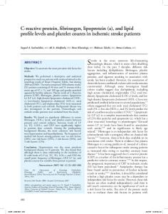
Figure 1: To the human eye, this Data Matrix symbol may appear to be flawless. However, this symbol does not meet barcode quality requirements for some industries and may be unreadable by certain barcode readers.
Understanding the primary reasons for decoding failures can save operators valuable time and effort when diagnosing reading issues. It also allows businesses to safeguard their processes and profitability by equipping their operations with the optimal tools and conditions for preventing data loss and process failures further down the line. The most common causes of unreadable barcodes are low contrast, quiet zone violations, improper reading position, print or mark inconsistency, and damage or distortion.
Low Contrast In order to extract data from the elements (1D bars or 2D cells) of a barcode, a barcode reader must be able to differentiate between the light and dark elements of the symbol. Both element types are essential for proper decoding, enabling a barcode reader to obtain the precise patterns of barcode elements that represent encoded data in the symbol. Depending on the method used to apply a barcode (whether printed by ink or marked by abrading a material’s surface in the case of direct part marks), as well as what kind of material is used, light or dark elements may alternately manifest as either the markings on a surface (the code itself), or the background (substrate material) onto which the marks are applied. If there is not enough contrast between these two barcode elements, a barcode reader may be unable to distinguish the barcode from its substrate, and the result may be a no-read.
Figure 2: Dark barcodes printed on dark backgrounds (like this 1D barcode on cardboard), or light symbols marked on light or reflective materials (like this 2D Data Matrix on metal), can cause no read results due to poor contrast between light and dark symbol elements.
Another example of low contrast is lack of uniformity of the light and dark barcode elements. This can be affected by the consistency of the marking or printing method in producing light or dark elements evenly across the code, the amount of variation or noise in the background or substrate, or lighting conditions that cause reflections or shadows on the substrate. These uniformity issues can make a barcode reader blind to the barcode. In cases where the barcode can still be decoded, low contrast or nonuniformity of barcode elements can dramatically slow a reader’s
1
www.microscan.com
Technology White Paper decode time and can limit the distance at which a barcode can be read.
Figure 6: The effects of proper lighting on etched metal.
Figure 3: A series of Data Matrix symbols directly marked on metal vary in readability due to noisy background caused by the inconsistent substrate.
Possible Solutions Ensuring distinct and uniform barcode elements is the first step to preventing unreadable codes due to low contrast. In cases where the printing or marking method is causing inconsistencies in barcode elements, it is important to adjust the printer or marking equipment to ensure that ink is applied evenly across the elements of the symbol, or that the marking equipment is abrading the substrate with uniform pressure.
Figure 4: Poor distribution of ink on this test tube barcode label has resulted in some white spots within the bar elements, which may lead to readability issues.
It is often the substrate onto which the code is applied that most dramatically affects the contrast of barcode elements. To deal with uneven, noisy, or highly-reflective substrates, or poor distinction between the substrate and the mark due to shadows or mark depth, the critical component is lighting. Lighting equipment for barcode reading is designed in a variety of geometries, tailored to produce the most uniform and highest-contrast images of barcodes marked by a number of means on a range of substrates. While diffused lighting may help to illuminate printed barcodes on glossy, flat surfaces, dark field lighting can apply low-angle beams of light to targeted regions of a substrate, enhancing the readability of embossed or engraved barcodes.
Figure 5: The effects of proper lighting on a glossy label.
Other factors to consider when addressing low contrast codes are the type of barcode and the type of reader being used in the application. Linear (1D) barcodes such as UPC/EAN and stacked symbols such as PDF417 must be distinguishable across the entire length of the symbol to capture all critical elements (in this case, bars) for decoding. If any of the bars of the barcode are obscured due to low contrast, the result can be a no-read for the entire code. Since linear barcodes are typically longer, good contrast must be obtained for a large surface area, as opposed to 2D symbols such as Data Matrix and QR Code, which are typically more compact.
Figure 7: The scan line of a laser barcode scanner must cross all bars in a linear barcode in order to ensure readability.
Laser barcode scanners (used exclusively for reading 1D codes) interpret a wave pattern created when the laser light bounces from the symbol back to the scanner. The reflections from the light and dark bars are processed and interpreted as characters. Linear barcodes typically require much higher contrast than 2D symbols – usually 80% or higher contrast between light and dark elements to acquire a uniform wave pattern. No-reads will occur when there is too little contrast between a code’s light and dark elements. In comparison, 2D imagers use cameras to capture images of 1D or 2D codes and require as little as 20% contrast between light and dark elements. For these reasons, using 2D symbols instead of 1D barcodes and, subsequently, 2D barcode imagers in barcode reading may decrease the possibility of unreadable codes due to low contrast.
Figure 8: Linear (1D) barcode scanners interpret reflections of laser light as wave patterns representing the light and dark elements of a symbol. These wave patterns illustrate the difference between high- and low-contrast barcodes.
2
www.microscan.com
Technology White Paper
Quiet Zone Violations The quiet zone is the area surrounding a barcode or 2D symbol that must be kept free of text, marks, or obstacles (also referred to as the “no-print zone”). All barcode readers have tolerances for minimum allowable quiet zone size. This space provides separation from surrounding marks, allowing the reader to “see” the code in its entirety. In 1D barcodes, the quiet zone lies to the left and right ends of the barcode. As a general rule, the quiet zone should be a minimum of 10 times the width of the narrowest bar of the 1D barcode. In 2D symbols, the quiet zone is the space surrounding the entire symbol. Quiet zone requirements for 2D symbols are prescribed by the Association for Automatic Identification and Mobility (AIM), which specifies at least a one-element (or cell) width on each side of the symbol. For best results with large 2D codes, it is typically recommended that the quiet zone be 10% of the symbol height or width, whichever is smaller.
When background noise or unexpected marks and debris enter the quiet zone, no-reads may be due to errors in the printing or marking method. Care should be taken to ensure that printing and marking equipment is working as expected to avoid unintended marks that may cause quiet zone violations. Additional lighting techniques can also be employed in situations where the quiet zone contains noise caused by reflections or shadows on an uneven substrate. When the area available to print or mark a barcode is limited by the overall surface area on a part, such as a densely-populated PCB or a tiny electrical component or medical device, quiet zone real estate may be difficult to come by. If quiet zones must be constrained, an operator may choose to employ a barcode reader with sophisticated decoding algorithms that accommodate minor quiet zone infringements. Some high-performance barcode reading technologies are capable of ensuring good reads even when the quiet zone is narrower than the prescribed minimums for 1D and 2D codes.
Figure 9: The quiet zone must be at least 10 times the width of the narrowest bar on either side of a linear (1D) barcode, or the width of one element on each side of a 2D symbol.
A reader may be unable to decode a symbol if text or other markings bleed into the symbol’s quiet zone. Or, quiet zone violations may yield inaccurately decoded data strings if the reader interprets non-symbol elements as part of the overall symbol. Possible Solutions Quiet zone violations are possibly the most easily-detected and resolvable causes of unreadable barcodes. This is because quiet zone violations are often due to a simple lack of planning for the inclusion of space around a printed or marked barcode or symbol. All that is needed to solve basic quiet zone violations is to adjust the printing or marking method – or the substrate – to accommodate the space requirements for minimum quiet zone. As much space as possible should be devoted to the quiet zone to reduce the chance of reading errors. There is no maximum specification for quiet zone width, so there is no reason to limit this space if not required.
Figure 10: As much space as possible should be provided for the quiet zone around a barcode, free from print and other elements.
Figure 11: A high-performance imager uses special algorithms to read codes with limited quiet zones, such as a Data Matrix on this crowded PCB.
Improper Reading Position In some cases, a readable barcode may receive a no-read result, not because of its print or mark quality, but due to the physical position of the barcode reader relative to the code. Depending on the technology, barcode readers may have unique requirements for reading codes at specific focal distances, angles, or orientations (in the case of tilted or rotated codes). Most barcode readers’ focal distances are limited by their internal optics. The barcode reader’s depth of field (the area from the closest possible read distance to the farthest possible read distance) determines exactly how near or far a reader can be positioned in relation to a barcode to ensure reliable decoding.
Figure 12: The specifications of a given barcode reader determine exactly how far away a reader can be positioned from a code in order to capture the code in focus within its read range.
3
www.microscan.com
Technology White Paper The angle at which a barcode reader scans or captures images of a symbol can also have an impact on its read performance. Mounting a barcode reader perpendicular to a code may cause specular reflection – the direct return of laser light (in the case of laser barcode scanners) or integrated LED lighting (in imagers) from the code or substrate – effectively “blinding” the reader. When this happens, a barcode reader may be unable to capture the entire code in high enough contrast, causing a noread result even if the code is flawless.
perpendicular to a barcode. Barcode imagers are also able to read barcodes in any orientation, and therefore do not need to be mounted at the same rotation as the code to ensure a reliable decode. In fact, barcode imagers may be the optimal choice in applications where codes are hand-applied to parts, or where parts are fed into equipment in unpredictable orientations, to ensure codes are read regardless of rotation or position.
Figure 15: Barcode imagers are capable of reading barcodes and symbols in any orientation.
Figure 13: Barcode readers should typically be mounted at an angle to barcodes to avoid direct reflections of light back to the reader.
No-read results can also occur if a barcode is presented to a barcode reader at a particular rotation or orientation that is not accommodated by the reader’s technology. Laser barcode scanners, for instance, must always be oriented in such a way that the laser’s scan line is perpendicular to the bars of the barcode. If this orientation deviates such that the scan line does not cross all elements (bars) of the barcode, the barcode will not be properly decoded.
For applications with space constraints and geometric challenges, options for mounting barcode readers within equipment may be severely limited. Right-angle mirrors can be incorporated in these cases to allow readers to “see” barcodes even when they are not positioned in direct view of the barcode. Using right-angle mirrors, an operator can aim a scanner’s laser to a code and back, or reflect barcode images back to an imager, enabling good reads even from challenging positions. Many barcode readers contain special algorithms for decoding mirrored images, which may be necessary for decoding barcodes that appear “flipped.”
Possible Solutions It is important to refer to a barcode reader’s technical specifications to ensure that the limitations and requirements regarding the reader’s position in relation to a code are taken into consideration when mounting a reader into equipment or presenting a code to a reader. If application requirements are challenging, it may be appropriate to employ a barcode reader that is better-suited to accommodating unpredictable barcode distances, angles, and orientations. For instance, barcode readers with built-in autofocus are able to decode symbols reliably at variable distances within their depths of field without manual focal adjustment. Even more capable are liquid lens autofocus barcode readers, whose lenses – containing actual liquid that is manipulated for increased or reduced curvature by electrical signals – are able to adjust to practically infinite focal distances, allowing for the greatest possible flexibility in read distances from the barcode.
Figure 14: Liquid reacts to electrostatic pressure to produce the appropriate lens curvature for a liquid lens barcode reader.
Applications with varying read angles and specific mounting requirements may benefit more from barcode imagers than laser barcode scanners. Imagers use built-in cameras to capture images of codes rather than relying on reflective laser beams, so their ability to read a barcode is less likely to be obstructed by specular reflections when the imager is mounted directly
Figure 16: When using right-angle mirrors, it is important to employ a barcode reader capable of reading both regular and mirrored images.
Print or Mark Inconsistency Variations in the printing or marking method, such as poor distribution of ink for printed codes or uneven pressure in surface abrasion during the direct part marking process, can be an underlying contributor to many readability issues. When printing and marking equipment do not produce and apply codes as expected, problems such as low contrast and quiet zone violations may result. There are several other causes of poor barcode quality or inconsistency that can cause trouble for barcode readers that are configured to “expect” symbols of a particular shape, skew, and uniformity: Axial Non-Uniformity – The amount of deviation along a symbol’s major axes. In this example, the symbol’s Y-axis is clearly greater than its X-axis. This inconsistency of X- and Y-dimensions typically indicates unexpected movement of the substrate as the barcode is applied by a printer or direct part marking device.
4
www.microscan.com
Technology White Paper
Contrast – The difference between the light and dark elements of a barcode, or between the code and its quiet zone and other perimeter elements. In this example, the dark elements (etch marks) and the light elements (the substrate) are too close in value due to low pressure in the marking process, undermining readability. Grid Non-Uniformity – The amount of deviation in a barcode’s bar or cell elements from the ideal grid of a theoretical “perfect symbol.” Printing or marking errors that cause grid non-uniformity (usually due to unexpected movement of the substrate during code application) will produce a code that appears skewed or distorted, which may be unreadable by standard decoding devices. Modulation – The uniformity of light and dark elements of a barcode. In these examples, the dark elements of the symbol do not have a consistent value. This issue, like low contrast, is often due to inconsistent distribution of ink for printed codes or uneven abrasion for direct part marks. Print Growth – The deviation (larger or smaller) of symbol element size from the intended or theoretically “perfect” element size for a particular symbol. When a symbol is printed, the ink may “bleed” when it comes in contact with the substrate, causing an overprint. If there is not enough ink or pressure applied by printing or marking equipment, the result may be an underprint. Quiet Zone – The area surrounding a barcode that must be kept free of text, marks, or other obstacles. In this example, a barcode has been printed outside of the designated quiet zone area and is overlapping with other elements on the substrate. This could be due to misalignment or movement of the substrate in relation to the printing equipment. Reflectance – The reflectance of light from a symbol’s light or dark elements that allow a barcode reader to distinguish symbol elements from the background (substrate material) and to distinguish light elements from dark elements. Low reflectance, as illustrated by this example, may increase the probability that a symbol element may be incorrectly identified as light or dark, causing a no-read result as the barcode reader attempts to interpret incorrect element patterns. Low reflectance may be caused by inconsistent print distribution or marking pressure by equipment.
Possible Solutions It is important to inspect and maintain printing and marking equipment regularly to ensure that high-quality, consistent barcodes are produced and applied to parts to avoid no-reads. When printing barcodes using ink-based methods such as Continuous Inkjet (CIJ), Thermal Inkjet (TIJ), Piezo Drop on Demand
(DOD), or High Resolution Case Coding, care should be taken to verify the correct distance of the printhead, clean and unblocked printheads and nozzles, and ensure the correct speed and setup of the printing process. If barcodes are produced by laser coding, correct focal distance and a continuous power supply to the equipment ensures high-contrast printing without losses in print distribution or speed. Thermal Transfer (TTO) and Direct Thermal (DTO) methods use wax or resin ribbon (or other thermal media) to apply barcodes to the substrate, so it is important to avoid ribbon wrinkles, to verify correct insertion of the ribbon into equipment, to use high-quality ribbon or other thermal material, and to use quality printheads and platen rollers for evenly-applied barcodes without missing elements.
Figure 17: Ink-based case coding equipment prints linear barcodes directly onto cardboard packaging. Movement of products during printing and variations in product speed can greatly impact the quality of these barcodes at the time they are applied.
The key to producing high-quality marks by direct abrasion is consistent pressure of the abrading component against the substrate. Direct part marking is accomplished by a number of methods, such as electromechanical etch, laser etch, chemical etch (methods in which codes are “scratched” into the substrate) and dot peen (a percussive method in which the symbol is hammered into the substrate with a metal stylus). It is important to verify the quality of the material used to create the abrasion (laser, chemical, or metal stylus) and the amount of power supplied to the marking equipment to ensure that barcodes are applied uniformly and with consistent pressure.
Figure 18: A dot peen direct part marking system uses a metal stylus to pound elements into a metal surface. It is important to ensure mark pressure is consistent when marking to avoid uneven or low-contrast symbols.
In addition to – and sometimes in lieu of – devoting excessive time and effort to maintaining perfectly-functioning printing and marking equipment, operators may choose to safeguard their operations against print or mark inconsistency by using more powerful barcode readers. Barcode readers engineered with sophisticated decoding algorithms are able to read codes with a wide variety of quality issues, such as shape, skew, and uniformity deviations from the characteristics of the theoretically “perfect” barcode. Of course, even with high-performance readers, regular maintenance of equipment should not be avoided.
5
www.microscan.com
Technology White Paper
Damage or Distortion While printing and marking inconsistencies pose their own decoding challenges, the risk of no-reads can persist even with high-quality barcodes. Barcode quality may degrade as parts move through operations and are exposed to various environmental factors. Harsh conditions may cause enough damage or distortion to the barcode or substrate to render even the best-quality barcodes unreadable. Damage can range from minor scratches, partial obstruction of the code by blotches, stains, or even debris causing torn or entirely missing barcodes. Distortion – Several environmental factors can contribute to barcode distortion in terms of shape, contrast, element uniformity, and substrate integrity. For example, temperature changes in a production environment can cause condensation to form on a code, blotching ink or distorting the substrate to a point at which the barcode’s elements are no longer discernable to the reader.
Figure 19: Environmental conditions have damaged this linear code to the point where significant portions of the bars have been blotched out, rendering it unreadable by standard equipment.
Fixed Pattern Damage – Damage to patterns of barcode elements, which the reader interprets as data, can significantly undermine readability. In 2D symbols such as this Data Matrix, Fixed Pattern Damage refers to missing elements in the symbol’s “finder pattern” (the outermost rows and columns of the symbol), which includes the “L-pattern” (the solid left and bottom rows of symbol elements) and “clock pattern” (the elements on the symbol edges opposite the “L”). These patterns allow the barcode reader to interpret the barcode orientation and number of rows and columns appropriately for decoding. Obstruction of these symbol patterns by scratches, stains, debris, or other material can render the barcode unreadable.
Figure 20: The critical elements of a Data Matrix symbol, including the L-pattern, clock pattern, and data storage area. Readability of the symbol is dependent capturing all critical elements clearly enough for the barcode reader to interpret data.
barcode elements from the view of the reader – unintended material abrasions, marks, surface stains, or excess material (debris or even mounting fixtures) – can cause no-read results. The images below are just a few examples of barcode damage.
Figure 21: Examples of barcode damage including material obstructions, scratches, and marks.
Possible Solutions Once a barcode is released into a production environment, consistent barcode quality can be difficult to maintain. In operations that use barcodes to track and identify items even after they have been transported between facilities or sold to customers to be read by new barcode reading equipment, the means for preventing or resolving barcode damage and distortion is very limited. Some preparation can be done at the outset of code production to limit future damage – such as choosing a substrate resistant to harsh environmental conditions, printing or marking barcodes so they can withstand any anticipated environmental factors, and maintaining a production environment as free from potential sources of damage as possible.
Figure 22: Barcodes are read in a dusty food packaging facility, where extra care must be taken to ensure both barcodes and barcode readers withstand environmental conditions.
Certain code types provide the option of encoding special data to assist in the decode process even when the code is damaged. Data Matrix symbols offer multiple levels of error checking and correcting (ECC, which also stands for “error-correcting code”), the standard being ECC-200, which is based on Reed-Solomon error correction principles. Reed-Solomon error correction allows as much as 50% of the Data Matrix to be damaged without rendering it unreadable. Error correction is encoded as elements in the data storage area of the code, increasing data recoverability by presenting symbol data to the reader in multiple ways. Almost all applications have accepted ECC-200 Reed-Solomon error correction as the standard, as it is the best error correction methodology available for the Data Matrix code type.
Other Damage – The environmental conditions to which a barcode may be exposed are limitless, and so are the ways in which a barcode can incur damage. Any kind of damage that obstructs
6
www.microscan.com
Technology White Paper
Figure 23: The Reed-Solomon method of error correction enables decoding even if as much as 50% of the Data Matrix is obscured. Here, ECC 200 symbol is reliably decoded despite partial obstruction.
Although as much care as possible should be taken to prevent no-reads due to barcode damage, it is often preferable to focus on the capabilities of the barcode reader rather than on the barcode itself. For the most challenging applications, in which barcode damage or distortion is unpredictable, high-performance readers are usually installed from the outset. Barcode readers engineered with the most powerful decoding algorithms feature advanced symbol location, gradient or reflectivity analysis, and the ability to grid-map the symbol image to produce an ideal, reliably-decodable symbol during processing. Barcode readers like these may also offer symbol reconstruction technology – a method by which the reader uses an algorithm to piece together discontinuous symbol data from multiple scan lines. In the case of partially-obscured or rotated symbols, the algorithm combines incomplete code segments into the equivalent of a single, complete scan line, which can then be decoded by the reader.
above, but also to grade codes against specific thresholds of acceptable quality for each readability parameter. This is especially important for identifying no-read issues with codes containing multiple errors - such as overprinting in addition to fixed pattern damage. Verification ensures not only that codes will be readable at the time they are presented to a barcode reader, but it can also be used to monitor and predict the degradation of codes over time, even when these degradations are not discernible to the human eye. Some verification equipment can be programmed to alert operators when barcodes fall below a threshold of acceptable quality so that it is evident when a printer, a piece of marking equipment, or a marking process begins to fail. Barcode verification equipment is a company’s greatest defense against unreadable barcodes, but it can be more expensive and difficult to install than high-performance barcode readers. When the primary concern is simply to read barcodes (and not ensure 100% quality), advanced barcode readers may be the best choice.
Figure 25: Machine vision software is used to verify a symbol against the ISO 15416 standard for barcode quality and monitor fluctuations in code quality over time.
Conclusion
Figure 24: Symbol reconstruction algorithms create a single readable scan line from multiple incomplete pieces of a damaged or distorted barcode.
Advanced Barcode Quality Assurance When creating and reading high-quality barcodes, the best defense is a great offense. For applications in which code quality is of the utmost importance, or in industries where codes are required by federal mandate or customer contract to meet specific barcode quality standards (such as those proposed by AIM, ANSI, GS1, ISO, and other standards organizations), barcode verification equipment may be installed to detect the causes of unreadable barcodes before they result in errors throughout operations. Barcode verification systems including verifiers, machine vision cameras, and verification software are engineered not only to identify all the common readability issues described
While unreadable barcodes can be highly disruptive to a company’s operations, it is often quite simple to establish a defense against poor quality barcodes and the no-reads that result. The causes of unreadable barcodes commonly manifest as a limited set of fairly straightforward issues, including low contrast, quiet zone violations, improper reading position, print or mark inconsistency, and damage or distortion. Once the cause of barcode unreadability is defined, it can be addressed by taking simple preventive measures. In many cases, barcode printing and marking methods can be optimized to ensure that high-quality codes are produced from the beginning. But when grade-A barcodes are a luxury and reliable barcode reading is the priority, the aggressive decoding capabilities of high-performance barcode scanners and imagers ensure good reads every time and protect a company’s most valuable time and data.
w w w . m i c r o s c a n . c o m
7
©2015 Microscan Systems, Inc. 04/15