JOURNAL OF MICROELECTROMECHANICAL SYSTEMS, VOL. 3, NO. I , MARCH 1994
36
The Design, Fabrication, and Testing of Corrugated Silicon Nitride Diaphragms Patrick R. Scheeper, Wouter Olthuis, and Piet Bergveld
Abstract-Silicon nitride corrugated diaphragms of 2 mm x 2 mm x l p m have been fabricated with 8 circular corrugations, having depths of 4 1 0 , or 14 pm. The diaphragms with 4-pm-deep corrugations show a measured mechanical sensitivity (increase in the deflection over the increase in the applied pressure) which is 25 times larger than the mechanical sensitivity of flat diaphragms of equal size and thickness. Since this gain in sensitivity is due to reduction of the initial stress, the sensitivity can only increase in the case of diaphragms with initial stress. A simple analytical model has been proposed that takes the influence of initial tensile stress into account. The model predicts that the presence of corrugations increases the sensitivity of the diaphragms, because the initial diaphragm stress is reduced. The model also predicts that for corrugations with a larger depth the sensitivity decreases, because the bending stiffness of the corrugations then becomes dominant. These predictions have been confirmed by experiments. The application of corrugated diaphragms offers the possibility to control the sensitivity of thin diaphragms by geometrical parameters, thus eliminating the effect of variations in the initial stress, due to variations in the diaphragm deposition process andlor the influence of temperature changes and packaging stress.
I. INTRODUCTION
S
ILICON (condenser) microphones are provided with a thin diaphragm. Several diaphragm materials have been applied, as for example Mylar [I], [2], silicon nitride [31, 141, and silicon [SI, [6]. The size of the diaphragms is typically between 1 x 1mm2 and 2 x 2 mm2, with a typical thickness between 150 nm and l p m . The sensitivity of these thin diaphragms to a sound pressure (typically between 20 pPa and 20 Pa) is strocgly dependent on the stress in the diaphragm. The tensile stress in thin silicon nitride films is typically of the order of lo8 N/m2 [7]. The stress in silicon diaphragms is determined by the diaphragm fabrication process. The tensile stress in heavily boron-doped silicon diaphragms is equal to [6]. Bergqvist er al. [5] fabricated silicon 7 x lo7 N/m diaphragms with a low doping level and a negligible stress. In general, thin film microphone diaphragms show an initial stress which strongly determines the sensitivity of the microphone. The initial stress can be controlled within certain limits by the parameters of the deposition process. The runManuscript received May 14. 1993; revised November 4, 1993. Subject Editor, N. de Rooij. This work was supported by the Dutch Foundation for Fundamental Research on Matter (FOM). P. R. Scheeper was with the MESA Research Institute, University of %ente, 7500 AE Enschede, The Netherlands. He is now with Briiel and Kjaer, 2850 Naerum, Denmark. W. Olthuis and P. Bergveld are with the MESA Research Institute, University of Twente, 7500 AE Enschede, The Netherlands. IEEE Log Number 92 15320.
I
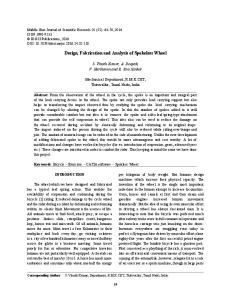
Fig. I. Schematic cross-sectional view of a circular corrugated diaphragm and characteristic parameters.
to-run reproducibility is determined by the reproducibility of the initial conditions of the reactor (affected by contamination, adsorbed water, previously deposited layers) and the accuracy of the instruments which control the reactor temperature, the pressure and the mass flow of the process gases. Variations of a factor 2 of the initial stress have been measured. It is advantageous if the mechanical sensitivity of the microphone diaphragms is not determined by deposition process parameters. A possible method to achieve this may be the application of a corrugated diaphragm, as shown in Fig. 1. In this figure, the corrugated diaphragm is provided with a flat center zone. It has first been shown by Jerman [8] that corrugated diaphragms can be made accurately in silicon using micromachining techniques. It has been calculated that a corrugated zone in a diaphragm can reduce stress with a factor 1000-10000 [9]. Therefore, one of the applications of corrugated diaphragms is the decoupling of a mechnical sensor from its encapsulation [9], [lo], in order to reduce the influence of temperature changes and packaging stress. Recently, Spiering er al. [ 111 have demonstrated a reduction of thermal stress with at least a factor 120 in a corrugated diaphragm. Flat diaphragms show a nonlinear relation between the deflection and the applied pressure. For relatively small deflections, this relation is approximately linear. The nonlinearity for large deflections is caused by stress due to stretching of the diaphragm. It has been experimentally shown that corrugated diaphragms have a larger linear range than flat diaphragms [8], [12], because of the achieved reduction of the radial stress in the diaphragm. The reduced influence of thermal stress and packaging stress, and the larger linear range compared with flat diaphragms, make the corrugated diaphragms attractive for specific applications, as for instance pressure sensors [8] and Fabry-Perot interferometers [ 131, [ 141. The application of corrugated diaphragms in microphones or capacitive pressure sensors may offer the possibility to control the mechanical sensitivity of the diaphragm by means of the dimensions of the corrugations, which are often easier to control than the parameters of a deposition process. In
1057-7157/94$04.00 0 1994 IEEE
37
SCHEEPER et al.: DESIGN OF CORRUGATED SILICON NITRIDE DIAPHRAGMS
this paper, the application of corrugated diaphragms for use in microphones is studied. Haringx [15] and Di Giovanni [16] have presented analytical models in which the effect of initial stress in the diaphragm is not included. The results of a finite element models describing the reduction of (thermal) stress by a corrugated zone were presented by Spiering et al. [9], by Ding [17], and by Zhang and Wise [SI. The deflection due to a homogeneous pressure was calculated by Ding [17] and by Zhang and Wise [18]. Unfortunately, the finite element calculations are only valid for a specific diaphragm geometry and size, and therefore the results cannot be applied to other diaphragms. In a recent paper, Spiering et al. [ 113 show that the flat center zone of a square diaphragm with a deep circular corrugation (deeper than 25pm) can be modeled as a stress-free circular membrane with a clamped edge and free radial movement. In this paper, it will be shown that for a diaphragm with shallow corrugations, the initial stress has a considerable effect on the mechanical behavior of the diaphragm. An analytical model will be presented in Section I1 for circular corrugated diaphragms with initial stress. In Section 111, the fabrication of corrugated diaphragms is discussed and in Section IV results of measurements are shown. 11. THE MECHANICAL SENSITIVITY OF
CORRUGATED DIAPHRAGMS
The center deflection, W O , of a flat, circular diaphragm with clamped edges and without initial stress, due to a homogeneous pressure, P, can be calculated from [8] Ed P = 5.33---
hi
WO
(1 - U’) R: hd
Ed hi WO” + 2.83--------(1 - u 2 )R; hi
(1)
where Ed, U,R d , and hd are the Young’s modulus, the Poisson’s ratio, the radius and the thickness of the diaphragm, respectively. It can be seen from (1) that if (wo/hd)