The BY91-1 Machine: A CC-NUMA Multiprocessor Architecture Tao Li , BenWei Rong, XiaoLi Wang, Ying Lu, XiuWen Zhai,GuoZhang Lu, Hui Zou ,and ChunYing Mao Beijing Institute of Data Processing Technology P.O.Box: 3927, Beijing, 100854 People's Republic of China Abstract BY91-1 machine is a prototype implementation of the CC -NUMA ( Cache Coherent Nonuniform Memory Access) multiprocessor architectures. Several mechanisms are combined to achieve its high performanc e: coherent shared memory provides a global, linear address space; versatile directory scheme ( Dir nNB+L) maintains both cache coherence and synchronization between processors in a uniform fashion; customized crossbar is optimized for high performance data transfers and signaling. This paper describes the experience gained by designing, fabricating, and running a complete parallel system. Specifically, it shows the effectiveness of the BY91 -1 architecture and how the mechanisms are integrated to produce a coherent system.
Index Items Shared Memory Multiprocessors, CC-NUMA Architecture, Cache Coherence, Synchronization, Crossbar
1.Introduction The limitations of uniprocessor speeds and the ability to replicate low cost, high performance processor s and VLSI components have provided the impetus for the design of multiprocessor. Currently, the different multiprocessor architectures fall under two primary categories: namely, message passing based multiprocessors and shared memory based multiprocessors[1]. In the message passing model, data is distributed among the processors and processors pass shared information by value, i.e., by sending messages. The programmer is responsible for maintaining the consistency of shared data. In contrast to the message passing model, the shared memory model provides processors in a multiprocessor system with a shared address space. Application can pass information by directly accessing shared memory. The shared memory model is natural for parallel computations. Also it is known that a shared memory communication such as a read or write takes much less time compared to a message passing communication such as send or receive. In a shared memory multiprocessor, private cache memories can reduce the memory latency problem due to program locality[2]. Nevertheless, the use of private caches in a multiprocessor system gives rise to the cache coherence problem: several caches can contain a copy of a particular main memory block, but a processor requiring a copy of a memory loca tion must always receive the most up -to-date version. Meanwhile, It is necessary to automatically prevent processors from simultaneously modifying their respective copies of a same line and a processor must not read a line while another processor is writin g it. Shared memory multiprocessor with private caches should resolve the issues of cache coherence and synchronization between processors. The BY91 -1 machine efficiently integrates supports for cache coherence and hardware based synchronization primitives by using a uniform directory scheme that is dubbed as Dir nNB+L. This integration allows for low hardware overhead while maintaining both coherent caches and indivisible memory accesses in a cohesive fashion. The most demanding application for high performance interconnect networks are shared memory multiprocessors because they tend to need more bandwidth and generate more irregular, fine grained traffic[1]. The performance of shared memory multiprocessors depends critically on the latency. A crossbar sys tem is insensitive towards traffic patterns by virtue of being full connects. By providing high bandwidth to each node with a uniform interface, crossbar is well match to shared memory systems with distributed caches. Unfortunately, crossbar is rarely used to build a multiprocessor interconnect system because it requires Θ(n2) switching elements, which are difficult to control efficiently and are hard to implement once their size becomes too large to fit on one integrated circuit. However, these problems ar e technology dependent and a recent innovation in FPGA has led to a new implementation of crossbar switches that does not share above problems. Moreover, this new technology has several characteristics that allow us to configuration our design according to the architecture feature
of BY91-1 machine. The experiences gained by implementing a 9 × 4 size crossbar shows that this way is cost -effective and flexible. The remainder of this paper is organized as follow: Section 2 presents the BY91 -1 architecture an d its implementation. Section 3 describes the rationale and design of a versatile directory scheme (Dir nNB+L) for resolving both cache coherence and synchronization. Section 4 deals with the architecture of the crossbar chip. Section 5 briefly presents our system software strategy. Finally, Section 6 summarizes the insight gained from implementing BY91 -1 and describes plans for our future research.
2. BY91-1 Architecture[3]
CM0
CM1
CM2
CM3
CROSSBAR(9 4)
CE1
CBI
CE7
IPIU
CE0 Motorola 68030
cache i860
LM(16MB)
I/O
o la 68030
LM(8MB)
IP
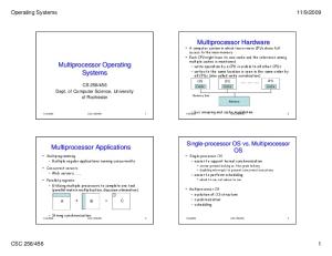
Figure 1. BY91-1 System Architecture
Figure 2 Photograph of BY91-1 Machine
The BY91 -1 architecture , as depicted in Figure 1, comprises of 8 computational elements (CE), 4 shared memory modules (CM), a 9×4 nodes crossbar, and an interactive processor (IP). Each component has the following configuration and feature: (1) Shared memory (CM0-CM3) A shared memory module contains 8M byte DRAM, 4M byte of data and 4M byte of directory ( to support a 4M byte portion of shared memory). A Communications and Memory Management Unit (CMMU) integrated in each shared memory module services data requests from processors and executes the whole DirnNB+L protocol. (2) Computational element (CE0-CE7) Each CE node consists of an Intel i860XP processor, 32K byte of on -chip cache, 8M byte of private (unshared) memory, and a crossbar interface(CBI) through which communications and shared memory accesses can be made. (3) Crossbar Network ( CBN)
The CBN contains a 9 ×4 switches array, which can simultaneously provides up to 5 chann els for low latency, high throughput, and point-to-point communication. Moreover, it has several characteristics that support for cache coherence. (4) Interactive Processor ( IP) IP is the host node of BY91 -1 machine. It was derived from a unit of S10/12, a high performance multiprocessor system designed by our S10/12 research group. IP node consists of two Motorola 68030 CPUs, 64K byte of off -the-shelf cache, 16M byte of private memory. I/O devices and Ether network are connected with IP via standard inte rfaces. IP Interface Unit(IPIU) is responsible for interpreting IP’s memory operations to crossbar interface. Figure 2 shows the physical realization of the BY91-1 machine. The whole hardware is packaged in a 70×30×30 cm rack. A Passive backplane provides the hard wires to connect CE, CM with crossbar. User access to BY91 -1 machine is through IP. External NFS file access is also provided by the host.
3. A Versatile Directory(DirnNB+L) for BY91-1 Machine 3.1 Coherent Shared Memory The BY91-1 machine provides hardware support for cache coherent shared memory. Cache lines in BY91 -1 are 32 byte in size and are kept coherent through a hardware based scheme call Dir nNB. This scheme implements a write -invalidate full-map directory protocol without broadcast capability. Full map directory[4] stores enough states associated with each block in shared memory so that every cache in the system can simultaneously store a copy of any block of data. That is, each directory entry contains N pointers, where N is the num ber of processors in the system. Full map directory based scheme provides an attractive mechanism for cache coherence because it relies only on point -to-point interconnects. When a processor wishes to write into a block, the directory sends point-to-point messages to processors with a copy. Although BY91-1 provides the abstraction of globally shared memory to programmers, the system’s shared memory is physically partitioned into 4 modules interleaving at 32 byte boundary. Each 32 byte memory line has a dire ctory entry associated with it. All coherence operations for a given memory line are coordinated by its directory entry. Each CM module contains the data and coherence directories for 4M byte portion of shared memory.
3.2 Fine-Grain Synchronization The primary advantage of fine -grain synchronization is that more parallelism can be exposed to the underlying hardware or software system than if coarse-grain synchronization techniques, such as barriers, were employed. For example, a process synchronizing at a barrier has to wait for the arrival of all other synchronizing processes before proceeding, regardless of whether that process depends on results computed by the other processes. By synchronizing on exactly the data words to be consumed, the fine grain synchronization eliminates false dependencies and allows a process to proceed as soon as the data it needs is available[5][6]. The BY91-1 machine provides hardware primitives support for fine -grain synchronization. Hardware support consists of a lock for each 32 byte data. Lock and unlock instructions are provided to respectively perform test&set and reset operations on a lock. In BY91 -1, the odd data width introduced by locks does not impact DRAM, cache, or crossbar data width. At memory side, a loc k is stored in the least significant 32 bit of a 32 byte shared memory block. At cache side, they are declared as cache disable because the widely sharing and high read/write ratio characteristics of these semaphores will give rise to malicious invalidation pattern[7]. Spinning on test&set instruction can cause a lot of network traffic. In BY91 -1, this network traffic was reduced substantially by exploiting a local spinning mechanism. In such case, a lock waiting list is established and maintained when more than one processor acquire the same lock. If the test&set operation is successful, the issuing processor is now defined to be the lock holder. The successive test&set operations by other processors will be inserted into lock waiting list and the value “set” is returned. The corresponding processors will perform busy -waiting locally without generating bus traffic. An ulock operation unsets the designated lock and removes the processors recorded by the lock list, if the list is not empty. The processors in t hat list will be notified to perform test&set operations again. This lock list reduces bus traffic of test&set operation. To eliminate the deadlock issue, some hardware and control logic are needed to form and maintain this lock list.
3.3 DirnNB+L Protocol A distributed directory scheme allows efficient implementation of a lock list at minimal extra cost. We discover that the combination of the full map directory and lock list can reduce hardware requirement while maintains cache coherence and synchronization between processors. We dubbed this hybrid scheme as DirnNB+L[8][9]. The BY91 -1 directory format is shown in figure 3. Directories are 32 bit wide and are stored in off -chip RAM. Each entry contains a 9 bit full map vector, a TAG bit, a LOCKB bit and a 4 bit LOCKCEID field. The full map vector makes the
directory controller have the full knowledge about the identity of those processors that have a copy of that memory block in it private cache or are waiting for a lock. The LOCKB bit indicates the states of a lock, namely, free or busy. The LOCKCEID field provides identity of the processor that has acquired the lock. The TAG bit is used to indicate whether the shared memory block has been cached. The high order 16 bit of a directory entry is reserve d for future purpose or modification. 31
- 15
14
Reserved
-7 CE0-CE7
6
5 IP
4
3 TAG
-0 LOCKB
LOCKCEID
Figure 3. A Hardware Directory Entry in BY91-1 The Dir nNB+L scheme incorporates a full map directory and a lock list to force the directory controller to interpret bo th atomic and no-atomic memory access patterns in the same way. For no-atomic shared data accesses, this scheme served as a normal DirnNB protocol which can be described according to the processor memory references: Read hit: The operation can be carried out locally in the cache. Read miss: A load request will be sent to the memory module. The TAG bit will be set. The directory supplies a copy to the requesting cache and adds the requesting CE node to its copyset. Write hit: The directory sends invalidation commands to those nodes appearing in directory copyset except the processor performs this write. The memory copy is updated. Write miss: Consistency commands are send to those processors that have cached that memory block for invalidating their copies . The memory copy is updated and the TAG bit is cleared to indicate there is no cache copy of this memory block. For atomic shared data access, Dir nNB+L works as a lock recorder. When a processor wants to acquire exclusive read/write to a memory cell, it first performs a lock operation on a semaphore or lock. After receiving this operation, the directory controller will check the directory entry associated with the memory block which is allocated for that lock. If the LOCKB bit of that directory entry is unset, the lock operation is successful. The directory controller then sets the LOCKB bit to indicate a processor has acquired that lock. The identity of that processor was copied to LOCKCEID field. The corresponding memory cell allocated to that lock is set by directory controller and the original value 0 is returned. If another processor requires the same lock, directory controller then checks the LOCKB bit. If the LOCKB is set and the LOCKCEID mismatches with the identity of current requesting processor, the new requesting processor identity is added to copyset to indicate that there is another processor want to get that lock. When atomic memory access terminates, the processor performs an unlock operation on that lock. After receiving that unlock operati on, the directory controller clears LOCKB bit to indicate the lock is free and checks the directory entry. If the lock list is not empty, the directory controller sends messages to inform the processors in the lock list to perform test&set operations again. In BY91-1 multiprocessor systems, special memory pages are used to allocate locks. These pages are declared as cache disable. So a directory entry allotted to a cache line will not collide with a lock. This collision free characteristic warrants the safety sharing of a directory entry between full map directory and lock list.
4. Design and Implementation of Crossbar on BY91-1 Machine In the absence of implementation constraints, the ideal processor interconnect system is the crossbar switch, becaus e it provides full connectivity at uniformly low latencies and peak throughput that is simply the bandwidth of a node interface multiplied by the number of nodes in the system. Crossbar switches can implement any permutation and support arbitrary multicasting. Unfortunately, the implementation of crossbar switches is costly, which is largely due to the fact that it requires Θ(n2) switching element for n nodes. Furthermore, it becomes increasingly difficult to control a crossbar as its size grows. In the pas t decades, crossbar is often integrated in a single Application Specified Integrated Circuit(ASIC) chip. Nevertheless, this way is expensive and inflexible for building a prototype like BY91 -1. The Field -Programmable Gate Arrays(FPGAs) provide the benefits of custom CMOS VLSI, while avoiding the initial cost, time delay, and inherent risk of a conventional masked gate array. In BY91 -1 machine, we use Xilinx FPGA XC4000 to design a 9 ×4 crossbar switches. This section presents the design and implementation of this crossbar.
4.1 Architecture Overview The crossbar contains two major subsections as shown in figure 4. The first section is the Crossbar Management Unit(CBMU), which can be regarded as a communication protocol processor. The CBMU logic deals wi th all bus
transactions on each communication port[10]. The second section is Crossbar Transfer Unit (CTU) which served as transceivers for creating dynamic point -to-point connection[11]. Each communication port has 90bit, which contains 64bit data, 32bit address ( multiplexed with least -significant 32bit of data line), 9bit ECC code and some room for protocol related information. Address Decoder and Bus Arbitrator
CBMU Bus Requirement Acknowledge
CFW Routing
and Synchronization CE0
CM0
CTU Xilinx FPGA XC4010 6 3 Array
CE1 CE2
�
�
�
�
CM1 CM2 CM3
CE3
90Bit
IP CE4
CE5
CE6
CE7
Figure 4. FPGA Based Crossbar Design
4.2 Crossbar Control and Arbitration The arbitration mechanism exploits the characteristics of both strict priorities and statistical fairness. In BY91 -1 machine, the following events may generate messages passing through crossbar, namely, (1) CE i (0≤i≤7) read CM j (0≤j≤3); (2) CE i write CMj; (3) CMj invalidate cache copy of CEi; (4) IP read CE i; (5) IP write CEi; (6) IP read CM j; (7) IP write CM j. These events can be divided into 3 classes according to their priorities. Event with the highest priority is (3). Medium priority events include (1), (2), (6), and (7). The se two kinds of events have more privilege because they are all deal with shared data, which can potentially be the bottleneck of the whole system. On the other hand, a priority in turn policy is employed to provide resources equally to all communication p orts and avoid dead -lock. The combination of this two arbitrary mechanism reduces memory latency while maintains statistical fairness.
4.3 Shared Memory Operations Shared memory access is started by a CPU trying send the address of the shared memory location through the crossbar interconnect system to a memory controller. CBMU arbitration will guarantee that only one request will be received by memory. In BY91 -1 machine, crossbar can support for burst memory read/write operations. Burst cycles allow t he maximum bus transfer rate by eliminating unnecessary driving of the address bus. Given the address of the first transfer, external hardware can calculate the address of subsequent transfers. With these address eliminated from the bus, a new data item ca n be transferred every clock period. The burst length is specified by LEN and CACHE# signals of each communication port. Table 4.1 shows how the LEN and CACHE# determines cycle length.
W/R# LEN
0 0 1 -0 0 1 0
CACHE# KEN#
0 0 0 0 1 1 1 --
1 -1 1 1 -1 0
-1 ---1 -0
Cycle Description
Nocacheable 64 bit (or less) read Nocacheable 64 bit (or less) read 64 bits (or less) write I/O and special cycles Nocacheable 128 bit read Nocacheable 128 bit read 128 bit write cache line fill
Burst Length
1 1 1 1 2 2 2 4
Table 4.1 Cycle Length Definition
4.4 Coherence and Synchronization Support In a shared memory multiprocessor, once a write cycle has completed, all subsequent read cycles on any node will return the new value. It also guara ntees write atomicity: the order of two writes will be observed by all remote node in the same order. Given that crossbar provides broadcasting of all operations, snooping could be considered as a way to maintain consistency, but this is not practical because the receiver can listen only to one channel at a time. In BY91-1, crossbar uses a special signal called SNPSTB# to assert a point -to-point invalidation operation. Two additional signals, LOCK# and UNLOCK# are added to support for atomic accesses on shared memory.
5. System Software Strategy The software system of BY91-1 contains monitor, BYSOS operating system, utilities of operating system, and a parallel C/C++ programming language developing kit[12]. The BY91 -1 operating system, BYSOS, manages the BY91-1 hardware resources. It is modified to exploit the hierarchical nature of the BY91 -1 architecture. The BYSOS can provide multitasking and virtual memory management of the BY91 -1 memory system. It also offers system calls for creating, starting, and stopping tasks, and calls for inter-task synchronization. BY91-1 has compiler for parallel version of ANSI C. For parallel C, BY91-1 supports extensive parallel libraries. The BY91 -1 system combines the mechanisms of heterogeneous multiprocessing and symm etric multiprocessing. In BY91-1, IP takes the charge of maintaining file system and peripheries, scheduling and communicating with CE. After the cross-compiling on IP, it then loads the parallel tasks to CE and communicates with the monitor. When the parallel tasks are terminated, the monitor informs IP to get the result data from shared memory.
6. Conclusion The BY91-1 represents a step in the maturation of multiprocessing technology. BY91 -1 is unique in its combination of coherent caches for shared me mory, support for fine -grained computation, and a high performance crossbar. These mechanisms provide an integrated solution to the problem of communication and synchronization in a parallel system. At this time, effort is underway to build a 16 node scal able machine. Although BY91 -1 addresses many of the issues of CC-NUMA architecture, it is essentially a no -scalable machine. Our feature work will investigate mechanism for salability, and forms the basis of a new architecture.
Acknowledgments This research has been supported by the National Defensive Science and Technology Committee with the project called BY91-1.
References [1] Kai Hwang, Advanced Computer Architecture: Parallism, Scalability, Programmbility, Mc Graw-Hill, Inc, 1993. [2] James R .Goodman, Using Cache Memory to Reduce Processor Memory Traffic, Architecture, 1983, pp.124-133.
Proc. 10th Ann. Symp. Computer
[3] Tao Li, The Hardware Design of BY9 -1 Multiprocessor System, Technical Report, BeiJing Institute of Data Processing Technology, Oct. 1996. [4] David Chaiken, Craig Fields, Kiyoshi Kurihar, and Anant Agarwal, Directory Based Cache Coherence in Large Scale Multiprocessors ,IEEE Trans. Computer, Vol. C-23, No.6, June 1990, pp.49-58. [5] James R. Goodman, Mary K. Vermon, and Philip J. Woest, Efficient Synchronization Primitives for Large Scale Cache Coherent Multiprocessors. In the Proceedings of the International Conference on Architectural Support of Programming Languages and operating systems, 1989, pp.64-73 . [6] Anant Agarwal, Ricardo Bianchini, David Chaiken, Kirk L. Johnson, David Kranz, John Kubiatowicz, Beng -Hong Lim, Kenneth Mackenzie, and Donald Yeung, The MIT Alewife Machine: Architecture and Performance, Proc. 22nd Int’l Symp. on Computer Architecture, 1995, pp.2-13. [7] Anoop Gupta and Wolf -Dietrich Weber, Cache Invalidation Pattern In Shared Memory Multiprocessors , IEEE Trans. Computers, Vol.41, No.7, July, 1992, pp.794-810 [8] XiuWen Zhai, Double Function and Full -Mapping Directory: Data Consistency and Lock Computer Engineering and Science, Vol18, No.3, July, 1996, pp.74-83 .
Cell Implementation,
[9] Tao Li, A Cache Coherence Protocol for Large Scale Multiprocessors System , Master’s Thesis, Beijing Institute of Data Processing Technolngy, April, 1996. [10] XiaoLi Wang, The Design of a Crossbar Mangement Unit on BY91 Data Processing Technolngy, Oct. 1996.
-1 machine,Technical Reprot,Beijing Institute of
[11] BenWei Rong , The Design of a Crossbar Transfer Unit on BY91 -1 machine,Technical Reprot,Beijing Institute of Data Processing Technolngy, Oct. 1996. [12] Ying Lu, The Software Design of BY9 Processing Technology, Oct. 1996.
-1 Multiprocessor System , Technical Report, BeiJing Institute of Data