Testing and Troubleshooting IEC 61850 GOOSE-Based Control and Protection Schemes
Edsel Atienza Schweitzer Engineering Laboratories, Inc.
Presented at the 12th Annual Western Power Delivery Automation Conference Spokane, Washington April 13–15, 2010 Originally presented at the 63rd Annual Conference for Protective Relay Engineers, March 2010
1
Testing and Troubleshooting IEC 61850 GOOSE-Based Control and Protection Schemes Edsel Atienza, Schweitzer Engineering Laboratories, Inc. Abstract—IEC 61850 GOOSE (Generic Object-Oriented Substation Event) provides many advantages, including flexibility and reduced wiring, but introduces new challenges. Traditional tools and techniques cannot check the status of contacts and coils between intelligent electronic devices (IEDs) in a GOOSE-based scheme. Data on Ethernet networks are generally not documented in traditional substation wiring or elementary diagrams. The previous generations of relay test sets are not equipped to monitor GOOSE messages from relays. As hard-wired schemes are converted to GOOSE-based schemes, test personnel need new tools to document, test, and troubleshoot these schemes. New tools include the following: • New documentation • Relay communications diagnostics • Managed switches • Network protocol analyzers • GOOSE-enabled relay test sets This paper describes and compares the use of these new tools with traditional testing techniques.
I. OVERVIEW Although conventional tools such as jumpers, voltmeters, continuity testers, and timers cannot test and troubleshoot IEC 61850 GOOSE (Generic Object-Oriented Substation Event) schemes, apply the following basic testing principles to identify new tools and techniques: • Use complete and up-to-date documentation [1]. • Divide large schemes into smaller subsystems. • Test overall performance of schemes using timesynchronized data. • Create checklists or test plans [1]. Detailed documentation combined with thorough testing provides confidence and acceptance of new technologies, such as IEC 61850 GOOSE. Proper test tools and techniques minimize testing and troubleshooting time, reduce labor expenses, increase scheme availability, and increase overall system reliability. Serial fiber-optic links are commonly used to pass discrete information between intelligent electronic devices (IEDs). Logical connections closely follow the physical connections in these connection-based methods. Some of the overall test methods applied to serial fiber-optic links can also be applied to GOOSE schemes, but the multicast nature of GOOSE and the flexibility of Ethernet require additional documentation and new tools.
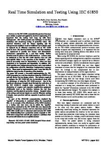
II. DOCUMENTATION Documentation is the basis of all test plans. In a hard-wired breaker failure scheme, elementary diagrams and wiring diagrams document all of the contact I/O required to pass breaker failure initiate signals from the line and bus protective relays to the breaker failure relays. In a hard-wired scheme, a wiring diagram simultaneously documents both physical and logical connections among IEDs associated with the scheme. In a system that uses GOOSE, the physical communications wiring diagrams do not adequately document the logical connections created by the publishing and subscribing of GOOSE messages. Each physical Ethernet connection can pass multiple messages in both directions simultaneously. The communications links shown in Fig. 1 can establish any or all of the following logical connections: • Breaker failure initiate from the line protective relays (21A, 21C, and 21D) to the breaker failure relays (50BF1, 50BF2, and 50BF3). • Breaker failure initiate from the bus differential relay (87B) to the breaker failure relays (50BF1, 50BF2, and 50BF3). • Breaker failure tripping from each breaker failure relay to the other breaker failure relays.
Fig. 1.
Example physical communications diagram
When documenting these logical connections, protection and control scheme designers must perform the following: • Identify all signals passed using GOOSE. • Identify the publisher of each signal. • Identify all subscribers of each signal. • Provide a checklist to test each IED. • Provide references to the physical connection diagram.
2
An example of using tables to document the logical connections is shown in Tables I and II. Organizing the list both by publishers and subscribers allows easy generation of checklists for commissioning testing, troubleshooting, and replacing failed equipment. Physical connection points in the table, including the switch and port numbers, aid in the review of managed Ethernet switch settings and association of logical connections with routes through the physical communications diagram. Specific data points of both publishing and subscribing IEDs link together logic diagrams between each pair of relays. Depending on the application, virtual local-area
network (VLAN) IEEE 802.1Q identifies and IEEE 802.1p priorities, multicast media access control (MAC) addresses, Internet Protocol (IP) addresses, standby backup connections, and subscriber GOOSE message quality data point assignments should also be included in the documentation. The IEC 61850 standard defines a Substation Configuration Language (SCL) to configure and document systems [2]. Future software tools may automate the generation of drawings and checklists using SCL-based files to aid in testing.
TABLE I LOGICAL CONNECTIONS BY PUBLISHER
Publisher
Subscriber
Message Name
Device
Switch
Port
Data Point
Description
Device
Switch
Port
Data Point
Description
21A
21A
1
1
TRIP
Line A Trip
50BF1
1
2
CCIN004
Initiate BF 1
21C
21C
1
3
TRIP
Line C Trip
50BF2
1
4
CCIN004
Initiate BF 2
21D
21D
1
5
TRIP
Line D Trip
50BF3
1
6
CCIN004
Initiate BF 3
50BF1
50BF1
1
2
BFTRIP
Breaker 1 Failed
50BF2
1
4
CCIN001
Trip Breaker 2
50BF1
50BF1
1
2
BFTRIP
Breaker 1 Failed
50BF3
1
6
CCIN001
Trip Breaker 3
50BF2
50BF2
1
4
BFTRIP
Breaker 2 Failed
50BF1
1
2
CCIN002
Trip Breaker 1
50BF2
50BF2
1
4
BFTRIP
Breaker 2 Failed
50BF3
1
6
CCIN002
Trip Breaker 3
50BF3
50BF3
1
6
BFTRIP
Breaker 3 Failed
50BF1
1
2
CCIN003
Trip Breaker 1
50BF3
50BF3
1
6
BFTRIP
Breaker 3 Failed
50BF2
1
4
CCIN003
Trip Breaker 2
87B
87B
1
7
TRIP
Bus B Trip
50BF1
1
2
CCIN005
Initiate BF 1
87B
87B
1
7
TRIP
Bus B Trip
50BF2
1
4
CCIN005
Initiate BF 2
87B
87B
1
7
TRIP
Bus B Trip
50BF3
1
6
CCIN005
Initiate BF 3
TABLE II LOGICAL CONNECTIONS BY SUBSCRIBER
Publisher
Subscriber
Message Name
Device
Switch
Port
Data Point
Description
Device
Switch
Port
Data Point
Description
50BF2
50BF2
1
4
BFTRIP
Breaker 2 Failed
50BF1
1
2
CCIN002
Trip Breaker 1
50BF3
50BF3
1
6
BFTRIP
Breaker 3 Failed
50BF1
1
2
CCIN003
Trip Breaker 1
21A
21A
1
1
TRIP
Line A Trip
50BF1
1
2
CCIN004
Initiate BF 1
87B
87B
1
7
TRIP
Bus B Trip
50BF1
1
2
CCIN005
Initiate BF 1
50BF1
50BF1
1
2
BFTRIP
Breaker 1 Failed
50BF2
1
4
CCIN001
Trip Breaker 2
50BF3
50BF3
1
6
BFTRIP
Breaker 3 Failed
50BF2
1
4
CCIN003
Trip Breaker 2
21C
21C
1
3
TRIP
Line C Trip
50BF2
1
4
CCIN004
Initiate BF 2
87B
87B
1
7
TRIP
Bus B Trip
50BF2
1
4
CCIN005
Initiate BF 2
50BF1
50BF1
1
2
BFTRIP
Breaker 1 Failed
50BF3
1
6
CCIN001
Trip Breaker 3
50BF2
50BF2
1
4
BFTRIP
Breaker 2 Failed
50BF3
1
6
CCIN002
Trip Breaker 3
21D
21D
1
5
TRIP
Line D Trip
50BF3
1
6
CCIN004
Initiate BF 3
87B
87B
1
7
TRIP
Bus B Trip
50BF3
1
6
CCIN005
Initiate BF 3
3
III. DIVIDE AND CONQUER Larger systems may include three or more Ethernet switches and other equipment in the path between GOOSE message publishers and subscribers. Troubleshooting a logical path through these systems includes the review of the publishing IED logic settings, publishing IED communications settings, physical connections to each device, Ethernet switch settings, subscribing IED communications settings, and subscribing IED logic settings. In hard-wired schemes, test switches, indicator lights, device terminals, panel terminal blocks, control house patch racks, and outdoor marshalling cabinets are common points to test between output contacts and input coils. In GOOSE-based schemes, use IED GOOSE diagnostic reports, port mirroring in managed Ethernet switches, and communications analyzer software to divide the system and isolate problems starting from the publishing IED towards the subscribing IED. In Fig. 2, the line IED publishes the status of its trip signal through three Ethernet switches to initiate the breaker failure logic in the breaker IED. When troubleshooting the breaker failure initiate signal shown in the example, analyze the SER (Sequential Events Recorder) and communications reports from the line IED first; then review data from Ethernet Switch 1. Follow the data through Ethernet Switches 2 and 3, and confirm function using the SER and communications reports from the breaker IED. IN
OUT
Ethernet Switch 2 OUT Ethernet Switch 1
Line Protection Algorithm
Line IED
IN
Communications Processing
SER
Analog and Contact I/O
IN
Ethernet Switch 3
OUT
Communications Processing
SER
Breaker Failure Algorithm
Breaker IED
Analog and Contact I/O
Fig. 2. Communications detail between publishing and subscribing IEDs in a large system
A. GOOSE-Enabled Relay Test Sets Prior to connecting IEDs to a protection or automation scheme, they are tested individually in a test laboratory or panel factory. These tests check the calibration of the IED, ensure installation of proper protection and logic settings, and prove contact I/O operate as expected. Traditional relay test sets apply voltages and currents and then monitor contacts to test individual IEDs. In a GOOSE-based scheme, contact I/O are replaced with GOOSE messages on the network. As voltages and currents are applied to IEDs, network traffic must be monitored by a network protocol analyzer, a subscribing IED, or a GOOSE-enabled relay test set, as shown in Fig. 3.
Configure IED to Publish
Line Protection Algorithm
Communications Processing
Line IED
GOOSE I/O
Relay Test Set
SER
Currents and Voltages
Analog and Contact I/O
Fig. 3.
Configure Test Set to Subscribe
Line IED CID File
Test set configured to subscribe to GOOSE messages
Although a network protocol analyzer or a subscribing IED can provide indication of a protection element operation, combining time-synchronized and time-stamped reports from multiple sources to document the test becomes lengthy and cumbersome. Without a time stamp or time synchronization between the test injection equipment and monitoring equipment, timing of protection algorithms cannot be measured. The use of GOOSE-enabled relay test sets reduces time and effort required to document and report results. Simplify configuration with the ability to import the Configured IED Description (CID) files used to set the communications of the IEDs. Also, test documentation becomes consistent with hardwired schemes because GOOSE I/O appear similar to contact I/O in test reports. GOOSE-enabled test sets are superior to network analyzers and extra IEDs when testing requires both simulation and monitoring of GOOSE messages, as shown in Fig. 4. The test set must simulate an initiate signal from the line IED to the breaker IED and monitor the breaker failure trip signal distributed from the breaker IED. Multiple CIDs must be imported into the relay test set to configure it to simulate the line IED and to subscribe to messages from the breaker IED. Import additional CID files into the relay test set to simulate breaker failure signals distributed by other breaker failure relays on the bus or to simulate the trip signal from the bus differential relay. Line IED CID File Test Set to Publish
Breaker IED CID File Test Set to Subscribe
GOOSE I/O
Relay Test Set Currents and Voltages
Configure IED to Subscribe to Line IED and Publish Breaker Failure
Communications Processing
Breaker Failure Algorithm
SER
Breaker IED
Analog and Contact I/O
Fig. 4. Test set configured to simulate line IED and monitor breaker IED GOOSE messages
4
B. IED GOOSE Diagnostic Reports Many GOOSE-enabled IEDs are able to generate diagnostic reports summarizing key real-time statistics of the GOOSE messages received and transmitted. Because no special equipment or settings are required to use the IED GOOSE diagnostic reports, these reports are the most commonly used tool when testing or troubleshooting GOOSE schemes. The IED GOOSE diagnostic reports are sufficient to verify communications links across small, simple networks using a single unmanaged Ethernet switch. These reports provide a quick summary of the IED GOOSE messages transmitted/published to the network and the messages received/subscribed from the network. The example reports in Fig. 5 show entries from both publishing and subscribing IEDs, corresponding to a message used to transfer a trip signal from a line IED to initiate breaker failure logic in a breaker IED. Line IED 21A GOOSE Transmit Status MultiCastAddr Ptag:Vlan StNum SqNum TTL Code ---------------------------------------------------------S21ACFG/LLN0$GO$S21A 01-0C-CD-01-00-01 4:2 2 140 1000 Data Set: S21ACFG/LLN0$DSet13 GOOSE Receive Status MultiCastAddr Ptag:Vlan StNum SqNum TTL Code ---------------------------------------------------------No GOOSE Rx subscriptions available Breaker IED 50BF1 GOOSE Transmit Status MultiCastAddr Ptag:Vlan StNum SqNum TTL Code ---------------------------------------------------------S50BF1CFG/LLN0$GO$S50BF1 01-0C-CD-01-00-02 4:1 2 594 852 Data Set: S50BF1CFG/LLN0$DSet13 GOOSE Receive Status MultiCastAddr Ptag:Vlan StNum SqNum TTL Code ---------------------------------------------------------S87BCFG/LLN0$GO$GooseDSet13 01-0C-CD-01-00-04 : 0 0 0 TTL EXPIRED Data Set: S87BCFG/LLN0$DSet13 S50BF3CFG/LLN0$GO$S50BF3 01-0C-CD-01-00-07 4:1 1 Data Set: S50BF3CFG/LLN0$DSet13
242
1999
S21ACFG/LLN0$GO$S21A 01-0C-CD-01-00-01 4:2 2 Data Set: S21ACFG/LLN0$DSet13
140
1554
S50BF2CFG/LLN0$GO$S50BF2 01-0C-CD-01-00-0A 4:1 1 Data Set: S50BF2CFG/LLN0$DSet13
154
3027
Fig. 5. GOOSE diagnostic reports from a pair of corresponding publishing and subscribing IEDs
The GOOSE diagnostic reports include the message label, multicast address, priority tag, VLAN identifier, and data set name. Real-time statistics for each message include the status number, sequence number, time-to-live (TTL), and error code [3]. Sequence numbers are incremented for every message that is published. State numbers are incremented for every state change in the data that are published. GOOSE diagnostic reports from publishing and subscribing IEDs with matching sequence and state numbers and continuously incrementing sequence numbers generally indicate that a healthy communications path is available between the IEDs. TTL and time-to-wait (TTW) correspond to the maximum time before the next message is sent or received [2]. Errors in the subscribing IED GOOSE diagnostic report, such as TTL expiration, coupled with healthy indications from the publishing IED GOOSE diagnostic report usually signify a physical connection problem or Ethernet switch settings problem. Use the GOOSE diagnostic reports to quickly verify establishment of all documented logical connections. Because of the multicast nature of GOOSE, these reports only document IED subscription at the ends of the communications links and cannot be solely relied upon to ensure availability of all redundant communications paths. They also do not provide any latency information between publishing and subscribing IEDs. C. Port Mirroring Advanced managed Ethernet switches buffer data, segregate networks, and prioritize data based on the IEEE 802.1Q and IEEE 802.1p standards. These standards allow efficient use of bandwidth and minimize latencies for time-critical GOOSE messages by restricting data to specific ports and reordering outgoing message packets [2]. VLAN identification (VLAN ID) settings make sure that IEDs receive only the messages that they should, based on the protection and control scheme design. Because of these functions, physically connecting equipment to the same Ethernet switch does not guarantee that messages pass between the equipment. Errors in Ethernet switch settings can prevent messages from passing to the next switch or the subscribing IED.
5
Fortunately, newer advanced Ethernet switches also provide the ability to inspect data entering and exiting each port using port mirroring, as shown in Fig. 6. This is similar to checking voltage at various terminal blocks and test switches between a contact and coil in a hard-wired scheme. Settings in an Ethernet switch allow ingress and/or egress data from a single port to be directly routed to a test port. A computer with a network protocol analyzer, GOOSE-enabled relay test set, or IED configured to subscribe to specific GOOSE messages can connect to the test port to verify messages are entering and leaving the switch on correct ports. Incorrect VLAN or prioritization settings in the switch can prevent or delay messages from being sent out of the required ports. Fig. 7.
Fig. 6.
Mirroring of ingress and egress data
IV. OVERALL SYSTEM TESTS Overall scheme timing and redundancy are important to all GOOSE schemes used for protection, especially in transmission substations. Depending on system conditions, a few milliseconds of additional delay in a breaker failure scheme can result in power system instability [4]. Simple verification of communications links using IED GOOSE diagnostic reports does not measure latency across a network or between publishing and subscribing IEDs. Redundant communication further complicates measurement of latency by varying the latency based on the routing of the messages. A. Latency Measurements Use traditional test sets and timers to check latency between publishing and subscribing IEDs when the IEDs are physically located close together. When IEDs are physically far apart, limitations such as test lead length, possibility of ground potential rise, or lack of time-synchronized test sets prevent the measurement of delays between IEDs. Program time-synchronized SER data in publishing and subscribing IEDs to provide send and receive times of data passed using GOOSE messages, as shown in Fig. 7. The difference in send and receive times in the SER reports represents the latency of message transit and processing between publishing and subscribing IEDs. IED time-stamped SER data can pass to substation real-time automation controllers for analysis, allowing continuous measurement, trending, and alarming of communications delays.
SER reports from publishing and subscribing IEDs
The transmission time is the maximum time allowed for a data exchange through a communications system. IEC 61850-5 describes the transmission time as the time duration between the action of communicating a value from the logic processing of one device to the logic processing within a second device as part of an application. Fig. 8 illustrates time ta as the time duration of the communications processing algorithm within the Physical Device 1 (IED 1). This algorithm uses data received from the input and logic processing of IED 1 as contents of messages that it creates and publishes. Detecting, processing, time-stamping, and creating an SER record of a physical contact input change of state in IED 1 are typical functions included in f1. Time tb represents the actual transit time of the message across the network between the IEDs. Time tc is the time duration of the communications processing algorithm within Physical Device 2 (IED 2), which receives and processes the message from IED 1. The function f2 in IED 2 represents processing the message contents received from IED 1, subsequent closure of a physical output contact, associated time stamp, and SER record [2]. Transfer Time: T = t + f2 Transmission Time: t = ta + tb + tc ta
f1
Communications Processing Algorithm
Physical Device 1
tb
tc Communications Processing Algorithm
f2
Physical Device 2
Fig. 8. SER time difference and transfer time, including time to detect, transfer, and process change
6
As shown in Fig. 8, the time duration to create and deliver messages between IEDs via a protocol is the message transmission time, represented by (1).
Test Long Path
B. Redundant Communication Because of the criticality of the data passed using GOOSE, redundant communications paths are commonly used to increase availability of GOOSE-based schemes. The Rapid Spanning Tree Protocol (RSTP) in a switch manages multiple communications paths and reconfigures the system topology in case of a physical path failure, such as a cut cable, failed port, or loose connection [2]. IED SER data and GOOSE diagnostic reports do not verify that all possible redundant paths are available. IED data alone also do not ensure latency across longer paths. In a test laboratory environment and during commissioning, both long and short redundant communications paths should be sequentially broken to check functionality and to measure latencies using all intended redundant paths, as shown in Fig. 9.
OUT
Ethernet Switch 2
(1) Transmission Time = ta + tb + tc The time duration to publish information in IED 1, deliver it via a protocol message, and act on it in IED 2 is the information transfer time, represented by (2). (2) Transfer Time = Transmission Time + f2 This information transfer time duration is the time truly useful to the design engineer because it represents actually performing an action as part of a communications-aided automation or protection scheme. Transfer time is easily measured as the time difference between the time-stamped SERs in IEDs with synchronized clocks. Message transit (tb) through the network, or message transit latency, is a subset of this difference. Existing Ethernet technology does not support measuring message transit latency. When using IED time-stamped SER data, ensure the timestamp accuracy is sufficient to measure the latencies. Many Ethernet-based time-set protocols, such as Distributed Network Protocol (DNP3), and low-resolution computer timesynchronization protocols, such as Network Time Protocol (NTP) and Simple Network Time Protocol (SNTP), lack sufficient accuracy to measure the latency of GOOSE-based schemes. High-accuracy IED clock time-synchronization and distribution techniques with accuracies of 1 millisecond or better, such as Global Positioning System time synchronization, IRIG-B synchronization, and IEEE 1588 Precision Time Protocol (PTP), must time-stamp data to measure latencies.
IN
Ethernet Switch 1
OUT IN
IN OUT
IN
Line IED
OUT
Ethernet Switch 3
Breaker IED
IN
OUT
Ethernet Switch 2
Ethernet Switch 1
OUT IN
Line IED
Fig. 9.
IN OUT
IN Test Short Path
OUT
Ethernet Switch 3
Breaker IED
Test redundant communications paths
V. CONCLUSIONS Traditional tools do not apply to GOOSE-based schemes. Applying primary testing and troubleshooting principles effectively identifies proper tools and techniques to test GOOSE-based schemes. Testing begins with proper documentation of all physical and logical communications links between publishing and subscribing IEDs to allow creation of checklists and test plans. Port mirroring, GOOSEenabled test sets, network protocol analyzers, and IED GOOSE diagnostic reports allow division of schemes into pieces that can be tested and monitored. Measure overall system delays using time-stamped, time-synchronized data from subscribing and publishing IEDs. Delays must be measured for different redundant communications paths. Using these tools and techniques demystifies GOOSE-based schemes and provides confidence to test personnel.
7
VI. REFERENCES [1]
[2]
[3]
[4]
K. Zimmerman and D. Costello, “Lessons Learned From Commissioning Protective Relaying Systems,” proceedings of the 62nd Annual Conference for Protective Relay Engineers, College Station, TX, March 2009. D. Hou and D. Dolezilek, “IEC 61850 – What It Can and Cannot Offer to Traditional Protection Schemes,” proceedings of the 35th Annual Western Protective Relay Conference, Spokane, WA, October 2008. H. Fischer, J. Gilbert, G. Morton, M. Boughman, and D. Dolezilek, “Case Study: Revised Engineering and Testing Practices Resulting From Migration to IEC 61850,” proceedings of the 18th Annual DistribuTECH Conference and Exhibition, Tampa, FL, January 2008. E. Atienza and R. Moxley, “Improving Breaker Failure Clearing Times,” proceedings of the 36th Annual Western Protective Relay Conference, Spokane, WA, October 2009.
VII. BIOGRAPHY Edsel Atienza received his BSEE from the University of Idaho in 2001. He joined Schweitzer Engineering Laboratories, Inc. (SEL) in 2002 as an international field application engineer. In 2006, he joined Tampa Electric as a substation operations engineer responsible for relay testing and maintenance. He returned to SEL in 2008, serving the southeastern United States as a field application engineer.
Previously presented at the 2010 Texas A&M Conference for Protective Relay Engineers. © 2010 IEEE – All rights reserved. 20100122 • TP6416-01