System FPGA
wSYSFPGA – 6809 System FPGA Setup Guide revision revision v1.5 For v1.3 boardset hardware
Table of Contents Board Requirements & Controls .............................. 4 Connectors 4 Joysticks and Controls 4 49 Way Joystick Support 4 Voltage & Current 5 BOOT UP ................................................................ 6 System Setup Menu ................................................ 7 SYSTEM SETTINGS............................................... 8 BOOT TO MACHINE TYPE HOLD 1P + 2P TO MENU SCREEN SAVER 49 WAY JOYSTICK BUTTON MAP SCHEME ROBOTRON 1P FIRE SPLAT 1P FIRE BUBBLES JOYSTICK SINI ROTATE STICK START BUTTON INPUT MENU BUTTON/COIN 3 VGA SCAN LINES SETUP MENU ON BOOT RESET TO DEFAULTS
8 8 8 8 9 9 9 9 10 10 10 10 11 11 11
OPTION SETTINGS.............................................. 12 HS RESET BUTTON BLASTER EXT SOUND ROBOTRON BUGFIX DEFENDER TURBO STARGATE TURBO
12 13 13 13 14
LOAD GAME ROMS ............................................. 15 LOAD wsfall.bin ERASE ALL ROM IMAGES
15 15
GAME ENABLE..................................................... 16 GAME ENABLE – CMOS SETTINGS
16
SWITCH TEST ...................................................... 17 DISPLAY TEST ..................................................... 17 SYSTEM UPDATE ................................................ 18 JAMMA to Original Wiring Harness Adapter ............. 19 Button and Video Sync Headers ............................... 20 ROM File Names & Directory Names........................ 22 USB flash drive top level directory structure.......... 22
Directory and File Names ...................................... 23 JAMMA Button Mapping ........................................... 31 Player 1 Button Inputs .............................................................31 Player 2 Button Inputs .............................................................31 Additional Buttons Header.......................................................31
Multi-WMS JAMMA Button Mapping ......................... 32 Revision History ........................................................ 33 FPGA Revisions 33 BOOT ROM Revisions 33 MCU Revisions 33 JAMMA Wiring Examples.......................................... 34 Base Wiring ........................................................... 34 Stargate................................................................. 35 Defender................................................................ 36 Panel Button & Joystick Layout................................. 37
3
Board Requirements & Controls Connectors The board uses a standard JAMMA connector, with player one and two buttons 4 & 5 being used in the ‘Standard’ input mode. A ‘multi-WMS’ mode is available where only player one & two buttons 1 through 3 are required. Refer to “Button Map Scheme” in the setup menu. The Three pin headers on the board are used for additional inputs and outputs. 2 pin = Video Sync output 4 pin = Additional inputs 16 pin = ( 2 x 8 )* = external soundboard and 49 way joystick connector * only 8 pins are required for 49-way joystick support
See the section “Button and Video Sync Headers” for pin connections. Mating connector types are: 2 position = molex kk 0.1” 22-01-3027 or TE Connectivity/AMP CST-100 0.1” 770602-2 4 position = molex kk 0.1” 22-01-3047 or TE Connectivity/AMP CST-100 0.1” 770602-4 16 position ( 2 x 8 )* = molex 90143-0016 or FCI 65043-029LF *single row 8 position for 49-way joystick = molex 90123-0108 or FCI 65039-029LF Joysticks and Controls Depending on the game setup the board requires two 8 way joysticks, for Robotron and Splat. The player 2 joystick can be used for directional firing in these game, or optionally player buttons 1,2,3,4 for the firing direction. Cocktail games will require two complete sets of player controls for each side of the cocktail table. 49 Way Joystick Support The 49 way joystick connection is for use ONLY with Sinistar and Blaster. It is not functional in the main menu, setup or in any other games. It supports only a single 49-way joystick. See the section “SYSFPGA v1.3 Board Layout & Connectors” for the pinout of the 49 way joystick connector.
4
Voltage & Current The board requires only 5v regulated DC power. Maximum current draw is 400mA when using a 4ohm speaker at maximum volume. A minimum of 500mA power supply should be used to ensure stable operation. If long runs of cabling are used significant voltage drop may occur, ensure the power supply is adjusted to provide a reliable 5v at the edge connector of the board. A voltage at the edge connector of the board under 4.75v will cause the board to suspend and remain in reset mode. Power Requirements 5v DC regulated 400mA
5
BOOT UP When first powered on, or when the board “BOOT TO” option set to “MENU”, the version numbers for the MENU, FPGA and sound/USB controller are displayed.
At initial power-on no games will have been loaded so the only option displayed is the “Setup
The Setup Menu allows loading of game ROMs and the configuration of board options and IMPORTANT NOTE: The setup menu can ALWAYS be accessed by pressing and holding down the JAMMA “SERVICE” ( Advance ) switch & powered on the machine or pressing RESET on the board.
6
System Setup Menu The option setup menu can be accessed from either the Main Menu, if “SETUP” is enabled, or at boot time by two methods. If the SETUP menu is disabled or “BOOT TO” is set to a game use either of the following methods to get to menu. •
Hold down the “SERVICE” ( Advance ) switch & power on the machine or press RESET on the board. This method is always available.
•
Press and hold 1P start and 2P start together & power on the machine or press RESET on the board. NOTE: This option can be disabled.
System options, ROM loading and updates are controlled from this menu. In turn each of the selections will be covered in the following pages:
7
SYSTEM SETTINGS Major hardware settings for the board are controlled from this menu
BOOT TO This option allows the board when powered on to start immediately in the selected game, bypassing the normal startup and menu. If a game ROM has been loaded it is available as a selection.
MACHINE TYPE cocktail
Enables the 2 player inputs and screen flipping for cocktail tables. This mode is only supported for Defender (Red), Stargate, Robotron & Bubbles.
Upright
Standard Machine
HOLD 1P + 2P TO MENU 1/2/4 OFF
Number of seconds that holding down 1P & 2P start button together will jump back to the game main menu. Disables the option to jump to then main menu when holding 1P + 2P start buttons.
NOTE: Even if “boot to” is set to a specific game holding 1P + 2P Start will jump back to the main menu unless this option is set to “OFF”
SCREEN SAVER ON/OFF If no buttons are pressed on the game select screen for 10 minutes the screen saver will automatically kick in. When in screen saver mode any button press will restart the menu. The screen save does not start when in the setup or game enabled menu.
8
FAST BOOT Enable fast startup of games. ON OFF
The self test of each game is disabled. There will be no ‘rug pattern’ or initial test message. Standard power on self test is run when a game is selected.
NOTE: If customized or non-standard game ROMs are used this option may need to be turned OFF.
49 WAY JOYSTICK Enable 49 way joystick through expansion pin header. ON OFF
49 way joystick support for a stick connected to the pin header on the board. Standard 8 way joystick input is translated into a 49 way joystick input.
NOTE: This option is ONLY available for Sinistar & Blaster. In all other games and in the menus the 49-way joystick has NO effect.
BUTTON MAP SCHEME STANDARD MULTI-WMS
Mapping uses player inputs and buttons 1 through 6. Refer to “JAMMA Button Mappings” Both 1P and 2P buttons 1 through 3 are used for inputs. Refer to “MULTI-WMS Button Mappings”
NOTE: For Cocktail Mode only STANDARD mapping should be used. Splat 2 player mode is NOT supported in MULTI-WMS mode
ROBOTRON 1P FIRE Inputs used for firing direction. Buttons 2P Joysticks
Inputs for buttons 1 through 4 are used for firing directions and should be connected to a joystick The JAMMA player 2 joystick is used for the firing directions.
NOTE: In cocktail mode this should be set to Buttons.
SPLAT 1P FIRE Inputs used for firing direction. Buttons 2P Joysticks
Inputs for buttons 1 through 4 are used for firing directions and should be connected to a joystick The JAMMA player 2 joystick is used for the firing directions.
NOTE: For true two player support the Buttons mode should be used and second pair of joysticks is required for player 2.
9
BUBBLES JOYSTICK 1P STICK / 2P STICK Select which joystick should be used for control in Bubbles.
SINI ROTATE STICK Rotates the joystick 90 degrees for Sinistar in both 49way and 8way mode. This allows sinister controls to be used when playing in a horizontal cabinet. NOTE: When playing in a horizontal cabinet the screen will be sideways. Sinistar still requires a vertically mounted monitor to play correctly. *This feature is only available with FPGA version 1.1 or later.
START BUTTON INPUT Controls how the 1P and 2P start buttons operate after a game is selected. This feature is only available with FPGA version 1.2 or later. •
WHEN PRESSED: The input for 1P and 2P start are passed directly into the game.
•
ON RELEASE: 1P and 2P inputs are only passed as “ON” into the game for ¼ of a second AFTER the button is released.
In this mode the 1P and 2P start inputs DO NOT REGISTER AS PRESSED WHEN THE BUTTON IS HELD DOWN. The purpose of this setting is that is allows 1P and 2P buttons to be held down, to jump back to the main menu, without a new game starting.
MENU BUTTON/COIN 3 The “menu” button can be configured as a third coin input for ‘Center Coin’. MENU Grounding the input will force a return to the main selection menu when button is grounded. It is an alternative way to get to the menu other than hold 1P & 2P Start buttons. COIN3 The input functions as ‘Center Coin’, this feature is for early version of Defender which featured a rd 3 ‘Center Coin’ input. *This feature is only available with FPGA version 1.3 or later
10
VGA SCAN LINES This option is only available in VGA mode. ON
Every other video line is blanked to give the appearance of a standard resolution CRT display.
OFF
Standard VGA mode every video line is displayed.
SETUP MENU ON BOOT This option allows disabling player start buttons for booting to the service menu. 1P+2P/SERVICE
When booting holding down 1P + 2P start buttons, or the JAMMA service button will start the System Setup Menu.
SERVICE ONLY
When booting ONLY holding down the JAMMA service button will start the System Setup Menu.
RESET TO DEFAULTS Hold down the 1P start button for approximately 2 seconds to clear the boot menu NVRAM settings back to the defaults. NOTE: This does not reset the individual game settings.
11
OPTION SETTINGS Secondary system settings are controlled in this menu
HS RESET BUTTON The High-score reset button used with Defender may be configured to share player 1 button 1. This option allows settings for defender to be adjusted without the need for a separate “high-score reset” button. It is recommended this option set to “enabled” for normal gameplay and only be set to “P1 BUTTON 1” when settings need to be changed. ENABLED
The “HRST” ( high-score-reset ) button input on the 4 pin header in enabled to function as the high-score-reset input.
P1 BUTTON 1
Player 1 button 1 also acts as the “high-score-reset” button.
NOTE: This option is enabled only for Defender
12
BLASTER EXT SOUND This option is only required if an additional soundboard is added to support stereo sound in an original Blaster cabinet. By default all sound triggers and handled by the internal micro-controller. To support stereo a second soundboard is required and would need to be wired to the external soundboard connector on the PCB.
OFF
Left & Right sound triggers are handled by the sound micro-controller on the PCB.
ON
Right sound triggers are ignored by the onboard sound controller and passed directly to the external soundboard header.
ROBOTRON BUGFIX The original Robotron ROMs contained a small but which was triggered by a graphics effect overwriting system memory. This patch corrects the problem and stops the corruption from occurring.
ON
Bug fix patch is automatically applied when Robotron ROMs are loaded
OFF
Bug fix patch is NOT applied and runs the risk of the “shot in the corner” crash.
IMPORTANT NOTE: DISABLING THIS OPTION MAY RESULT IN ROBOTRON CRASHING IF THE BUG CONDITION ARISES ! IT IS RECCOMENDED TO KEEP IT ENABLED AT ALL TIMES !
DEFENDER TURBO Defender hardware originally ran at a 1MHz clock speed, limited by the original hardware. This option allows a board populated with a 68B09 series CPU that is rated for 2MHz to run at the higher clock speed, speeding up program execution and removing some of the slow-down effects of Defender. For an experienced player this can make the game more challenging. OFF
Standard 1MHz CPU clock rate
ON [2MHz]
2MHz CPU clock rate
NOTE: It is only recommended this option be enabled ONLY on boards populated with a 68B09 CPU.
13
STARGATE TURBO This option allows stargate to run at 2MHz CPU clock rate ( see Defender Turbo ) OFF
Standard 1MHz CPU clock rate
ON [2MHz]
2MHz CPU clock rate
NOTE: It is only recommended this option be enabled for board populated with a 68b09 CPU.
14
LOAD GAME ROMS Using this menu game ROMs are transferred from USB flash drive to the gameboard’s internal flash memory storage. Loading ROMs ROM files must be unzipped raw binary and placed into directory folder on the root of the flash drive. When a set of game ROM has been loaded successfully the text will change to [LOADED] and the game automatically enabled in the “GAME ENABLE MENU”.
•
To load a ROM it must be in an unzipped binary format in a specified directory folder on the USB flash drive. Insert the flash drive with the game ROM images and select that option to load. See the following section for details of each directory and file name.
•
The option “LOAD wsfall.bin IMAGE” loads a single binary file containing all the game ROM images
LOAD wsfall.bin The file “WSFALL.bin” should be placed into the root folder of the USB flash drive, the file should contain all the game ROM images concatenated together into a single file. Once loaded successfully all games will be automatically enabled.
ERASE ALL ROM IMAGES ”ERASE ALL ROM IMAGES” will clear all of the stored ROM storage area on the internal flash on the gameboard. This will automatically disable all games and return the board to a blank state.
NOTE: see “ROM File Names & Directory Names” section for the directory name and ROM file names for each game that can be loaded.
15
GAME ENABLE This option allows the list of games which can appear on the main menu to be turned on or off. It also allows the use of a second set of game settings to be enabled. Each game allows for 2 completely independent sets of settings which includeds the high-score table, difficulty settings.
Each game allows for 2 completely independent sets of settings, if [ 2 CMOS is enabled ] when a game is selected then a second menu requests which settings should be loaded before playing the game.
GAME ENABLE – CMOS SETTINGS [2 CMOS] has been enabled so the option to select which to run is displayed.
16
SWITCH TEST Shows status of all switched inputs and the status of the 49-way joystick input header.
DISPLAY TEST Use this option to position and set the display to the center of the monitor. Also to adjust the colors if necessary. Four test screens are displayed showing a grid out to the edge of the display, then the colors, red, green, blue and finally colors bars along with white.
17
SYSTEM UPDATE This option is used to update the boot menu, FPGA firmware and the MCU program code if required. Updates will be placed into the root folder of the USB stick and the option selected. The onscreen display will show the progress of the update and if it was successful. Updates will cause the gameboard to automatically reboot if they are applied successfully.
Lower section of the screen displays the currently loaded versions. Filename for update are: MENU: FPGA: MCU:
18
WSFMENU.BIN WSFPGA.BIN WSFMCU.BIN
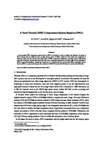
JAMMA to Original Wiring Harness Adapter
The connectors for Power, Video, Coin Door and Controls should be plugged into the keyed connectors of the original cabinet harness. Use the diagram to locate the plugs which should be removed from the original boards. Power, Video, Coin Door, Widget/Control Panel
Use the two mounting feet to secure the board over the top of the original gameboard, note the location of the two mounting screws. The video header on the original board will be blocked by the WSF board. Be sure to remove the video connector plug first.
19
Button and Video Sync Headers Two pin headers are also required for wiring the board to an original harness. 2 pin plug = required for the Horizontal and Vertical Sync 4 pin plug = required for the “high-score-reset” input and button 6 for Stargate.
NOTE: Ensure the VGA enable is OFF when used in an original cabinet ! NOTE: Ensure the Keying Pin on the JAMMA adapter lines up with the board. Do NOT use an unkeyed JAMMA adapter.
WARNING Plugging in an un-keyed JAMMA adapter the wrong way around could damage or DESTROY the board !
20
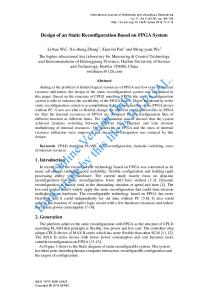
SYSFPGA v1.3 Board Layout & Connectors
21
ROM File Names & Directory Names Rom files should be stored on a USB flash drive with the directory folder named matching the name in the left column and the file names matching the name in the middle column. The size if provided for reference.
USB flash drive top level directory structure
22
Directory and File Names
Defender [Red ROM] Directory/Folder Name
ROM File Name:
Size
defender
defend.1 defend.2 defend.3 defend.4 defend.6 defend.7 defend.8 defend.9 defend.10 defend.12 defend.11
2048 4096 4096 2048 2048 2048 2048 2048 2048 2048 2048
defend.snd
2048
Defender [White ROM] Directory/Folder Name
ROM File Name:
Size
defender
rom1.bin rom2.bin rom3.bin rom6.bin rom7.bin rom8.bin rom9.bin rom10.bin rom11.bin rom12.bin
4096 4096 4096 2048 2048 2048 2048 2048 2048 2048
defend.snd"
2048
23
Defender [Green ROM] Directory/Folder Name
ROM File Name:
Size
defender
defeng01.bin defeng02.bin defeng03.bin defeng04.bin defeng06.bin defeng07.bin defeng08.bin defeng09.bin defeng10.bin defeng11.bin defeng12.bin
2048 4096 4096 2048 2048 2048 2048 2048 2048 2048 2048
defend.snd"
2048
StarGate Directory/Folder Name
ROM File Name:
Size
Stargate
01 02 03 04 05 06 07 08 09 10 11 12
4096 4096 4096 4096 4096 4096 4096 4096 4096 4096 4096 4096
sg.snd
2048
24
Joust Directory/Folder Name
ROM File Name:
Size
Joust
3006-13.1b 3006-14.2b 3006-15.3b 3006-16.4b 3006-17.5b 3006-18.6b 3006-19.7b 3006-20.8b 3006-21.9b 3006-22.10 3006-23.11 3006-24.12
4096 4096 4096 4096 4096 4096 4096 4096 4096 4096 4096 4096
joust.snd
4096
Joust [ RED ROM ] Directory/Folder Name
ROM File Name:
Size
Joust
joust.wg1 joust.wg2 joust.wg3 joust.sr4 joust.wg5 joust.sr6 joust.sr7 joust.sr8 joust.sr9 joust.sra joust.srb joust.src
4096 4096 4096 4096 4096 4096 4096 4096 4096 4096 4096 4096
joust.snd
4096
25
Robotron Directory/Folder Name
ROM File Name:
Size
Robotron
robotron.sb1 robotron.sb2 robotron.sb3 robotron.sb4 robotron.sb5 robotron.sb6 robotron.sb7 robotron.sb8 robotron.sb9 robotron.sba robotron.sbb robotron.sbc
4096 4096 4096 4096 4096 4096 4096 4096 4096 4096 4096 4096
robotron.snd
4096
Robotron [ Tie Die ] Directory/Folder Name
ROM File Name:
Size
roboTD
robotron.sb1 robotron.sb2 robotron.sb3 robotron.sb4 robotron.sb5 robotron.sb6 robotron.sb7 robotron.sb8 robotron.sb9 robotron.sba robotron.sbb robotron.sbc
4096 4096 4096 4096 4096 4096 4096 4096 4096 4096 4096 4096
robotron.snd
4096
26
Bubbles Directory/Folder Name
ROM File Name:
Size
bubbles
bubbles.1b bubbles.2b bubbles.3b bubbles.4b bubbles.5b bubbles.6b bubbles.7b bubbles.8b bubbles.9b bubbles.10b bubbles.11b bubbles.12b
4096 4096 4096 4096 4096 4096 4096 4096 4096 4096 4096 4096
bubbles.snd
4096
Splat Directory/Folder Name
ROM File Name:
Size
Splat
splat.01 splat.02 splat.03 splat.04 splat.05 splat.06 splat.07 splat.08 splat.09 splat.10 splat.11 splat.12
4096 4096 4096 4096 4096 4096 4096 4096 4096 4096 4096 4096
splat.snd
4096
27
Sinistar Directory/Folder Name
ROM File Name:
Size
Sinistar
sinistar.01 sinistar.02 sinistar.03 sinistar.04 sinistar.05 sinistar.06 sinistar.07 sinistar.08 sinistar.09 sinistar.10 sinistar.11
4096 4096 4096 4096 4096 4096 4096 4096 4096 4096 4096
speech.ic4 speech.ic5 speech.ic6 speech.ic7
4096 4096 4096 4096
sinistar.snd
4096
Sinistar [ AMOA ] Directory/Folder Name
ROM File Name:
Size
Sinistar
sinrev1.01 sinistar.02 sinrev1.03 sinrev1.04 sinrev1.05 sinrev1.06 sinrev1.07 sinrev1.08 sinrev1.09 sinrev1.10 sinrev1.11
4096 4096 4096 4096 4096 4096 4096 4096 4096 4096 4096
speech.ic7 speech.ic5 speech.ic6 speech.ic4
4096 4096 4096 4096
sinistar.snd
4096
28
Blaster Directory/Folder Name
ROM File Name:
Size
blaster
1.ic1 2.ic3 3.ic6 4.ic7 5.ic11 6.ic13 7.ic15 8.ic20 9.ic22 10.ic24
16384 16384 16384 16384 16384 16384 16384 16384 16384 16384
11.ic25 12.ic26 13.ic27
8192 8192 8192
14.ic35 15.ic38
16384 16384
16.ic39 17.ic41
4096 4096
18.sb13
4096
blaster.col
4096
29
Blaster [ Kit ] Directory/Folder Name
ROM File Name:
Size
blaster
blastkit.1 blastkit.2 blastkit.3 blastkit.4 blastkit.5 blastkit.6 blastkit.7 blastkit.8 blastkit.9 blastkit.10
16384 16384 16384 16384 16384 16384 16384 16384 16384 16384
blastkit.11 blastkit.12 blastkit.13
8192 8192 8192
blastkit.14 blastkit.15
16384 16384
blastkit.16 blastkit.17
4096 4096
blastkit.18
4096
blaster.col
4096
30
JAMMA Button Mapping As each game uses different button mapping these tables shows which button controls the input for each game. The mappings are for the “STANDARD” input mode which can support Cocktail mode games: Joystick controls are consistent across ALL games for up-down-left-right. Except for Defender/Stargate which do not use left & right and Joust which does not use Up/Down. In Cocktail mode player 2 buttons are used as inputs for a second player, only for games which support cocktail play Defender, Stargate, Robotron. Defender Inputs Stargate Player 1 Button Player 1 Button
Robotron BUTTONS Setting
Joust
Bubbles
Splat BUTTONS Setting
Blaster
Sinistar
1
P1 Fire
P1 Fire
P1 Fire Up
P1 Throw Up
Thust 2
2
P1 Thrust
P1 Thrust
P1 Fire Down
P1 Throw down
Thust 1
Fire
3
P1 Reverse
P1 Reverse
P1 Fire Left
P1 Flap
P1 Throw Left
4
P1 Smartbomb
P1 Smartbomb
P1 Fire Right
P2 Flap
P1 Throw Right
Fire
Sinibomb
5
P1 Hyperspace
P1 Hyperspace
Player Defender Inputs Stargate Player 2 Button
Robotron
Joust
Bubbles
Splat
Blaster
Sinistar
2 Button 1
P2 Fire*
P2 Fire*
P2 Fire Up*
P2 Throw Up
2
P2 Thrust*
P2 Thrust*
P2 Fire Down*
P2 Throw down
3
P2 Reverse*
P2 Reverse*
P2 Fire Left*
4
*P2 Smartbomb
*P2 Smartbomb
P2 Fire Right*
5
*P2 Hyperspace
*P2 Hyperspace
P2 Flap
P2 Throw Left P2 Throw Right
Additional Buttons Header Buttons used on the 4 Pin expansion header. Defender
Stargate
1
P1 Button 6
P1 Invisio
2
P2 Button 6
*P2 Invisio
3
Main Menu
Main Menu
Main Menu
4
High Score Reset
High Score Reset
High Score Reset
*buttons used only in cocktail mode
31
Multi-WMS JAMMA Button Mapping When the option “BUTTON MAP SCHEME” is set to MULTI-WMS mode only JAMMA buttons Player 1 button 1 to button 3 and Player 2 button 1 to button 3 are used. This Button Mapping scheme should only be used for upright cabinets, it is not designed to be used in a cocktail table machine.
The mapping is shown in the following two tables.
Player 1 Buttons DEFENDER
STARGATE
Button 1
Reverse
Reverse
Button 2
Hyperspace
Hyperspace
ROBOTRON
JOUST
BUBBLES
SPLAT
BLASTER
SINISTAR
JAMMA Player 1
Button 3
P1 Flap
Inviso
Blast
Sini Bomb
Player 2 Buttons DEFENDER
STARGATE
Button 1
Thrust
Thrust
Button 2
Fire
Fire
Button 3
Smartbomb
Smartbomb
ROBOTRON
JOUST
BUBBLES
SPLAT
BLASTER
SINISTAR
JAMMA Player 2 Thrust
P2 Flap
Blast
NOTE:
32
•
DO NOT use multi-WMS mode for cocktail mode games.
•
Dual player mode in Splat is NOT supported in Multi-WMS mode.
Fire
Revision History Manual Revision: 1.5
FPGA Revisions 1.01
- Initial release
BOOT ROM Revisions 1.00
Initial Release
MCU Revisions 1.00R Initial Release 1.01R No-operational changes 1.02R Bug fix for disabled Defender sound: When running Sinister from the menu Defender sound is disabled until next system reset
33
JAMMA Wiring Examples
Base Wiring Base wiring for a JAMMA board to original harness for Power, Video, Speaker and Coin Door.
Control wiring would be separate and based on the game to be run.
34
Stargate
35
Defender
36
Panel Button & Joystick Layout For a multi-game panel the following layout could be used. The input mode would have to be set to standard and both Robotron and Splat would be set to Player 2 joystick input ( “P2 Joystick” ).
Note: This arrangement would not support Splat simultaneous Two Player mode. An additional two joysticks would need to be added.
37