RE SEARCH
35
O
HL
I G H T S• VI S
I
Final report, Part C – Specific refurbishment concepts
G
Sustainable refurbishment of exterior walls and building facades. Final...
Sustainable refurbishment of exterior walls and building facades
HI
NS
• SC I E N CE• T
HNOLOG Y•
VTT TECHNOLOGY 33
ISBN 978-951-38-7849-8 (URL: http://www.vtt.fi/publications/index.jsp) ISSN 2242-122X (URL: http://www.vtt.fi/publications/index.jsp)
EC
VTT TECHNOLOGY 35
Sustainable refurbishment of exterior walls and building facades Final report, Part C – Specific refurbishment concepts Ruut Peuhkuri, Sirje Vares, Sakari Pulakka &Tarja Häkkinen, VTT Ari-Veikko Kettunen, Marja-Liisa Honkanen, Anne-Maria Vierinen, Sei Wha Vou, Alexander Bordachev & Markku Malila Vahanen Oy Andres Järvan, EKK Anna Svensson, SINTEF Colin King, Roger Sadgrove, Apeksha Gupta, Paul Littlefair, Chris Scott & Martin Brocklesby, BRE Christopher Tweed & Kruti Gandhi, Cardiff University Frances Voelcker, SGG Elías Hontoria & Leire Hontoria, REPAIR Nerea Benitez & Aitor Epelde, ONEKA Runar Skippervik, TOBB
ISBN 978-951-38-7851-1 (URL: http://www.vtt.fi/publications/index.jsp) ISSN 2242-122X (URL: http://www.vtt.fi/publications/index.jsp) Copyright © VTT 2012
JULKAISIJA – UTGIVARE – PUBLISHER VTT PL 1000 (Vuorimiehentie 5, Espoo) 02044 VTT Puh. 020 722 111, faksi 020 722 4374 VTT PB 1000 (Bergsmansvägen 5, Esbo) FI-2044 VTT Tfn +358 20 722 111, telefax +358 20 722 4374 VTT Technical Research Centre of Finland P.O. Box 1000 (Vuorimiehentie 5, Espoo) FI-02044 VTT, Finland Tel. +358 20 722 111, fax + 358 20 722 4374
Sustainable refurbishment of exterior walls and building facades Final report, Part C – Specific refurbishment concepts Ruut Peuhkuri, Sirje Vares, Sakari Pulakka et al. Espoo 2012. VTT Technology 35. 198 p. + app. 1 p.
Abstract This report is the third part of the final report of Sustainable refurbishment of building facades and exterior walls (SUSREF). SUSREF project was a collaborative (small/medium size) research project within the 7th Framework Programme of the Commission and it was financed under the theme Environment (including climate change) (Grant agreement no. 226858). The project started in October 1st 2009 and ended in April 30th 2012. The project included 11 partners from five countries. The coordinator of the project was Tarja Häkkinen, VTT. SUSREF developed sustainable concepts and technologies for the refurbishment of building facades and external walls. This report together with SUSREF Final report Part A and SUSREF Final Report Part B introduce the main results of the project. Part A focuses on methodological issues. The descriptions and the assessment results of the general refurbishment concepts are presented in SUSREF Final report part B (general concepts). This part – SUSREF, Final report, Part C – introduces the refurbishment concepts developed by the SME partners of the project. This report also presents the assessment results of these concepts. The following list shows the sustainability assessment criteria defined by the SUSREF project. 1) 2) 3) 4) 5) 6) 7) 8) 9) 10) 11) 12) 13) 14) 15)
Durability Impact on energy demand for heating Impact on energy demand for cooling Impact on renewable energy use potential Impact on daylight Environmental impact of manufacture and maintenance Indoor air quality and acoustics Structural stability Fire safety Aesthetic quality Effect on cultural heritage Life cycle costs Need for care and maintenance Disturbance to the tenants and to the site Buildability.
This report presents sustainability assessment results of specific refurbishment concepts and gives recommendations on the basis of the results.
3
The SME partners of the project improved and developed concepts for the refurbishment of exterior walls. The work focused on the chosen common walls types, building types and refurbishment technologies. The research organisations and universities of the project carried out assessments in accordance with the chosen approach. This report describes the concepts developed by: – – – – – –
Vahanen Oy (VAHANEN) Repair Estructuras S.L. (REPAIR) Oneka Architectura S.L, (ONEKA) Sustainable Gwynedd Gynaladwy Cyf (SGG) Ehituskonstrueerimise ja Katsetuste OU (EKK) and Trondheim og omegn boligbyggelag (TOBB).
As the starting point is the repair of the existing external wall. The wall types included to the company concepts are: – – – – – – –
–
Lime-sand brick wall; multi rise buildings and single family dwellings Nordic Europe. Sandwich element panels; multi rise buildings typical in Nordic Europe. Panels with mineral wool; multi rise buildings typical in Russia, Ukraine, Belorussia and Baltic countries. Prefabricated solid panels; multi rise buildings typical in Russia, Ukraine, Belorussia and Baltic countries. Brick walls with air cavity or decayed wool insulation; single- and multi-storey buildings in North European, Central (also Eastern) European countries. Wooden frame wall; detached and terraced house typical in Nordic Europe and also in the Northern Continental Europe. Cavity brick walls; single/detached family houses and multi-storey buildings in areas with dry, hot summer; and in areas with cold climate, without dry season and with warm summer. Solid thick wall (400–1000 mm) built with two faces of stonework without insulation; single and multi-storey buildings in areas of mild, wet, windy climate.
On the basis of the experiences, the systematic approach was found feasible and useful because it supported the product concept developers to – – – – – – –
iterate and optimize material and structural choices compare alternative solutions investigate the feasibility of new and innovative solutions avoid risks assess long-term impacts both from the view point of building performance and environmental and financials impacts consider both functionality and process related aspects develop systems with help of which clients are supported to set targets for refurbishment works.
Altogether 16 refurbishment concepts were developed. The refurbishment concepts developed by the SMEs are listed in the following:
4
1
Brick wall with ventilation gap and vacuum insulated panel
2
Re-SOLAR (structural solutions collect solar energy and both retain it for the heating and protect the building from overheating)
3
ETICS applied to sandwich element
4
ETICS (External thermal insulation composite systems) applied to sandwich element internal layer
5
ETICS applied to insulated panel RUS (RUS refers to possible areas of application)
6
ETICS applied to solid panel RUS
7
Filling brick wall cavities with carbamide resin foam
8
Thermo-reflective multi-foil outer insulation of brick wall with controllable ventilation air gap before insulation
9
Exterior refurbishment of wooden frame walls with a flex system board insulation
10
Transparent insulation
11
External insulation of solid rubble stone wall with vapour-open natural insulation material and ventilated timber cladding
12
External insulation of solid rubble stone wall with semi-vapour-open mineral wool insulation material and acrylic render
13
External insulation of solid rubble stone wall with expanded polystyrene insulation material and acrylic render
14
External shelter of solid rubble stone wall with unventilated dark-coloured steel sheet cladding
15
Internal insulation vapour-open of solid rubble stone wall with lime-sand pointing outside
16
Load bearing ventilated facade
The following information was developed for all concepts:
5
– – – – – – –
cross section figures of the existing wall cross section figures of the refurbishment solution material layers and thicknesses working methods areas of suitable application known problems related to refurbishment method market potential.
Keywords
Sustainable refurbishment, exterior wall, façade, sustainability assessment
6
Preface This report is the third part of the final report of Sustainable refurbishment of building facades and exterior walls (SUSREF). SUSREF project was a collaborative (small/medium size) research project within the 7th Framework Programme of the Commission and it was financed under the theme Environment (including climate change) (Grant agreement no. 226858). The project started in October 1st 2009 and ended in April 30th 2012. The project included 11 partners from five countries: VTT Technical Research Centre of Finland Stiftelsen SINTEF Vahanen Oy Cardiff University (CU) Building Research Establishment TECNALIA Repair Estructuras S.L. Oneka Architectura S.L. Sustainable Gwynedd Gynaladwy Cyf Ehituskonstrueerimise ja Katsetuste OU Trondheim og omegn boligbyggelag
VTT SINTEF Vahanen CU BRE TECNALIA Repair ONEKA SGG EKK TOBB
Finland Norway Finland UK UK Spain Spain Spain UK Estonia Norway
The coordinator of the project was Tarja Häkkinen, VTT. SUSREF developed sustainable concepts and technologies for the refurbishment of building facades and external walls. This report together with SUSREF Final report Part A and SUSREF Final Report Part B introduce the main results of the project. Part A focuses on methodological issues. The descriptions and assessment results of the developed concepts are presented in SUSREF Final report part B (generic concepts) and SUSREF Final report Part C (SME concepts). The main objectives of the SUSREF project were: to identify and understand the quantitative needs to refurbish building envelops in the EU and neighbouring areas; to understand the meaning of
7
these needs, in the first place, in terms of environmental impacts and secondly in terms of financial impact and business potential; to develop a systemized theory and different technologies for refurbishment of building facades and external walls in order to ensure the functional excellence of solutions; to analyse technologies from the view point of building physics and energy efficiency; to consider the various challenges in different parts of Europe in terms of present climate, technological differences, and cultural-historic differences; and finally to deliver sets of relevant performance specifications for sustainable refurbishment; to develop systemized methods for consideration of environmental performance of external walls; to assess and ensure the sustainability of the developed technologies in terms of environmental impacts, life cycle costs, social and cultural impacts; to develop sustainable concepts for carrying out refurbishments projects; to disseminate the results for a) building industry, b) standardisation bodies, and c) policy-makers and authorities in terms of technological knowledge, guidelines and recommendations. All deliverables are available on SUSREF web site http://cic.vtt.fi/susref/. The authors of the report are as follows: Ruut Peuhkuri, Sirje Vares, Sakari Pulakka, Tarja Häkkinen VTT, Finland Ari-Veikko Kettunen, Marja-Liisa Honkanen, Anne-Maria Vierinen, Sei Wha Vou, Alexander Bordachev and Markku Malila Vahanen Oy, Finland Andres Järvan, EKK, Estonia Anna Svensson,, SINTEF, Norway Apeksha Gupta, BRE, UK Christopher Tweed, Kruti Gandhi, Cardiff University, UK Frances Voelcker, SGG Elías Hontoria, Leire Hontoria, REPAIR Nerea Benitez, Aitor Epelde, ONEKA Runar Skippervik, TOBB In addition to the authors of the Final report Part B the following experts are acknowledged
Jonathan Williams, Jelena Kiselova and Nicholas Beddoe, BRE for text editing. Colin King, Roger Sadgrove, Paul Littlefair, Chris Scott, Martin Brocklesby, BRE for valuable comments.
8
Contents Abstract ........................................................................................................... 3 Preface ............................................................................................................. 7 List of abbreviations...................................................................................... 16 1.
Introduction............................................................................................. 19
2.
Methodology ........................................................................................... 22 2.1 Introduction ..................................................................................... 22 2.2 Building physical assessments ......................................................... 25 2.3 Laboratory test arrangements .......................................................... 27 2.4 Life cycle assessment and life cycle costing ..................................... 30
3.
Concept B1 by VAHANEN ....................................................................... 32 3.1 Buildability....................................................................................... 35 3.2 Known problems.............................................................................. 35 3.3 Maintenance and disturbance .......................................................... 35 3.4 Performance values used in assessment.......................................... 35 3.5 Durability assessment...................................................................... 36 3.6 Results from the laboratory tests ...................................................... 37 3.7 Impact on energy demand for heating and cooling ............................ 39 3.8 Impact on renewable energy use potential ........................................ 39 3.9 Environmental impact ...................................................................... 40 3.10 Indoor air quality and acoustics ........................................................ 42 3.11 Structural stability and fire safety...................................................... 42 3.12 Aesthetic quality and effect on cultural heritage ................................ 42
4.
Concept number 2 by VAHANEN ............................................................ 43 4.1 Fixing and exploded view of Re-Solar Concept ................................. 44 4.2 Ventilation and air supply details ...................................................... 45 4.3 Rationale and market potential ......................................................... 46 4.4 Application guidelines ...................................................................... 47 4.5 Buildability....................................................................................... 47 4.6 Maintenance and disturbance .......................................................... 48
9
4.7 4.8 4.9 4.10 4.11 4.12 4.13 4.14 4.15
Performance values used in assessment.......................................... 48 Durability assessment...................................................................... 48 Impact on energy demand for heating and cooling ............................ 48 Environmental impact ...................................................................... 48 Life cycle costs ................................................................................ 51 Indoor air quality and acoustics ........................................................ 51 Structural stability ............................................................................ 51 Fire safety ....................................................................................... 51 Aesthetic quality and effect on cultural heritage ................................ 52
5.
Concept T1a by Vahanen ........................................................................ 53 5.1 Cross sections of existing and refurbished wall ................................. 54 5.2 Rationale and market potential ......................................................... 54 5.3 Application Guidelines ..................................................................... 55 5.4 Buildability....................................................................................... 56 5.5 Known problems related to refurbishment method ............................ 56 5.6 Maintenance and Disturbance.......................................................... 57 5.7 Performance values used in the assessmen ..................................... 57 5.8 Durability ......................................................................................... 58 5.9 Impact on energy demand for heating and cooling ............................ 60 5.10 Impact on renewable energy use potential ........................................ 60 5.11 Environmental impact ...................................................................... 60 5.12 Life cycle costs ................................................................................ 62 5.13 Indoor air quality and acoustics ........................................................ 63 5.14 Structural stability and fire safety...................................................... 63 5.15 Aesthetic quality and effect on cultural heritage ................................ 63
6.
Concept T1b by Vahanen ........................................................................ 64 6.1 Cross sections of existing and refurbished wall ................................. 65 6.2 Rationale and market potential ......................................................... 65 6.3 Application guidelines ...................................................................... 66 6.4 Buildability....................................................................................... 67 6.5 Known problems related to refurbishment method ............................ 67 6.6 Maintenance and disturbance .......................................................... 67 6.7 Performance values used in assessment.......................................... 68 6.8 Durability assessment...................................................................... 68 6.9 Results from the laboratory tests ...................................................... 69 6.10 Impact on energy demand for heating and cooling ............................ 70 6.11 Impact on renewable energy use potential ........................................ 70 6.12 Environmental impact ...................................................................... 71 6.13 Life cycle costs ................................................................................ 73 6.14 Indoor air quality and acoustics ........................................................ 73 6.15 Structural stability and fire safety...................................................... 73 6.16 Aesthetic quality and effect on cultural heritage ................................ 73
10
7.
Concept T1c by Vahanen ........................................................................ 75 7.1 Cross sections of existing and refurbished wall ................................. 76 7.2 Rationale and Market potential......................................................... 76 7.3 Application Guidelines ..................................................................... 76 7.4 Buildability....................................................................................... 78 7.5 Known problems related to refurbishment method ............................ 78 7.6 Maintenance and disturbance .......................................................... 78 7.7 Performance values used in assessment.......................................... 79 7.8 Durability assessment...................................................................... 79 7.9 Impact on energy demand for heating and cooling ............................ 80 7.10 Impact on renewable energy use potential ........................................ 80 7.11 Environmental impact ...................................................................... 80 7.12 Life cycle costs ................................................................................ 83 7.13 Indoor air quality and acoustics ........................................................ 83 7.14 Structural stability and fire safety...................................................... 83 7.15 Aesthetic quality and effect on cultural heritage ................................ 83
8.
Concept T1d by Vahanen ........................................................................ 85 8.1 Cross sections of existing and refurbished wall ................................. 86 8.2 Rationale and market potential ......................................................... 86 8.3 Application guidelines ...................................................................... 86 8.4 Buildability....................................................................................... 89 8.5 Maintenance and disturbance .......................................................... 89 8.6 Known problems related to refurbishment method ............................ 89 8.7 Performance values used in assessment.......................................... 89 8.8 Durability assessment...................................................................... 90 8.9 Impact on energy demand for heating and cooling ............................ 91 8.10 Impact on renewable energy use potential ........................................ 91 8.11 Environmental impact ...................................................................... 91 8.12 Life cycle costs ................................................................................ 93 8.13 Indoor air quality and acoustics ........................................................ 94 8.14 Structural stability and fire safety...................................................... 94 8.15 Aesthetic quality and effect on cultural heritage ................................ 94
9.
Concept EKK1 ......................................................................................... 95 9.1 Cross sections of existing and refurbished wall (with air cavity) ......... 96 9.2 Cross sections of existing and refurbished walls (with decayed mineral wool) ................................................................................... 96 9.3 Rationale and market potential ......................................................... 97 9.4 Application guidelines ...................................................................... 97 9.5 Buildability....................................................................................... 98 9.6 Known problems related to refurbishment method ............................ 98 9.7 Maintenance and disturbance .......................................................... 98 9.8 Performance values used in assessment.......................................... 98 9.9 Durability assessment...................................................................... 99
11
9.10 9.11 9.12 9.13 9.14 9.15 9.16
Impact on energy demand for heating and cooling .......................... 101 Impact on renewable energy use potential ...................................... 101 Environmental impact .................................................................... 101 Life cycle costs .............................................................................. 103 Indoor air quality and acoustics ...................................................... 104 Structural stability and fire safety.................................................... 104 Aesthetic quality and effect on cultural heritage .............................. 104
10. Concept EKK2 ....................................................................................... 105 10.1 Cross sections of existing and refurbished wall ............................... 106 10.2 Rationale and market potential....................................................... 106 10.3 Application guidelines .................................................................... 107 10.4 Buildability..................................................................................... 107 10.5 Known problems related to refurbishment method .......................... 108 10.6 Maintenance and disturbance ........................................................ 108 10.7 Performance values needed in the assessment .............................. 108 10.8 Durability assessment.................................................................... 109 10.9 Impact on energy demand for heating and cooling .......................... 110 10.10 Impact on renewable energy use potential ...................................... 110 10.11 Environmental impac ..................................................................... 110 10.12 Life cycle costs .............................................................................. 114 10.13 Indoor air quality and acoustics ...................................................... 115 10.14 Structural stability and fire safety.................................................... 115 10.15 Aesthetic quality and effect on cultural heritage .............................. 115 11. Concept by TOBB ................................................................................. 116 11.1 Cross section of existing and refurbished wall................................. 117 11.2 Rationale and market potential....................................................... 117 11.3 Application guidelines .................................................................... 117 11.4 Known problems related to refurbishment method .......................... 119 11.5 Buildability..................................................................................... 119 11.6 Maintenance and disturbance ........................................................ 119 11.7 Performance values used in assessment........................................ 120 11.8 Durability assessment.................................................................... 120 11.9 Impact on energy demand for heating and cooling .......................... 121 11.10 Impact on renewable energy use potential ...................................... 123 11.11 Environmental impact .................................................................... 123 11.12 Life cycle costs .............................................................................. 125 11.13 Indoor air quality and acoustics ...................................................... 125 11.14 Structural stability and fire safety.................................................... 125 11.15 Aesthetic quality and effect on cultural heritage .............................. 126 12. Concept number 1 by ONEKA............................................................... 127 12.1 Cross sections of existing and refurbished wall ............................... 127 12.2 Rationale and market potential....................................................... 128 12.3 Application guidelines .................................................................... 131
12
12.4 12.5 12.6 12.7 12.8 12.9 12.10 12.11 12.12 12.13 12.14 12.15
Buildability..................................................................................... 132 Known problems related to refurbishment method .......................... 132 Maintenance and disturbance ........................................................ 133 Performance values used in the assessment .................................. 133 Durability assessment.................................................................... 134 Impact on energy demand for heating and cooling .......................... 134 Impact on renewable energy use potential ...................................... 134 Environmental impact .................................................................... 134 Life cycle costs .............................................................................. 137 Indoor air quality and acoustics ...................................................... 137 Structural stability and fire safety.................................................... 137 Aesthetic quality and effect on cultural heritage .............................. 137
13. SGG 1 by Gwynedd Gynaladwy Cyf ...................................................... 138 13.1 Cross section of existing and refurbished wall................................. 139 13.2 Rationale and market potential....................................................... 139 13.3 Application Guidelines ................................................................... 140 13.4 Buildability..................................................................................... 140 13.5 Known problems relating to refurbishment method.......................... 141 13.6 Maintenance and disturbance ........................................................ 141 13.7 Performance values used in assessment........................................ 142 13.8 Durability assessment.................................................................... 142 13.9 Impact on demand for heating and cooling ..................................... 143 13.10 Impact on renewable energy use potential ...................................... 143 13.11 Environmental impact .................................................................... 144 13.12 Life cycle costs .............................................................................. 146 13.13 Indoor air quality and acoustics ...................................................... 146 13.14 Structural stability and fire safety.................................................... 147 13.15 Aesthetic Quality and effect on cultural heritage.............................. 147 14. SGG2 by Gwynedd Gynaladwy Cyf....................................................... 148 14.1 Cross sections of existing (left) and refurbished (right) wall ............. 149 14.2 Rationale and market potential....................................................... 149 14.3 Application guidelines .................................................................... 150 14.4 Buildability..................................................................................... 151 14.5 Maintenance and disturbance ........................................................ 151 14.6 Known problems relating to refurbishment method.......................... 151 14.7 Performance values used in assessment........................................ 152 14.8 Durability assessment.................................................................... 152 14.9 Impact on demand for heating and cooling ..................................... 153 14.10 Impact on renewable energy use potential ...................................... 154 14.11 Environmental impact .................................................................... 154 14.12 Life cycle costs .............................................................................. 157 14.13 Indoor air quality and acoustics ...................................................... 157 14.14 Structural stability and fire safety.................................................... 157
13
14.15 Aesthetic quality and effect on cultural heritage .............................. 157 15. SGG3 by Gwynedd Gynaladwy Cyf....................................................... 158 15.1 Cross sections of existing and refurbished wall ............................... 159 15.2 Rationale and market potential....................................................... 159 15.3 Application guidelines .................................................................... 160 15.4 Buildability..................................................................................... 161 15.5 Known problems relating to refurbishment method.......................... 161 15.6 Maintenance and disturbance ........................................................ 161 15.7 Performance values used in assessment........................................ 162 15.8 Durability assessment.................................................................... 162 15.9 Impact on demand for heating and cooling ..................................... 164 15.10 Impact on renewable energy use potential ...................................... 164 15.11 Environmental impact .................................................................... 164 15.12 Life cycle costs .............................................................................. 167 15.13 Indoor air quality and acoustics ...................................................... 167 15.14 Structural stability and fire safety.................................................... 167 15.15 Aesthetic quality and effect on cultural heritage .............................. 167 16. SGG 4 by Gwynedd Gynaladwy Cyf ...................................................... 168 16.1 Cross sections of existing and refurbished wall ............................... 169 16.2 Rationale and market potential....................................................... 169 16.3 Application guidelines .................................................................... 170 16.4 Buildability..................................................................................... 171 16.5 Known problems relating to refurbishment method.......................... 171 16.6 Maintenance and disturbance ........................................................ 172 16.7 Performance values used in assessment........................................ 172 16.8 Durability assessment.................................................................... 172 16.9 Impact on demand for heating and cooling ..................................... 174 16.10 Impact on renewable energy use potential ...................................... 174 16.11 Environmental impact .................................................................... 174 16.12 Life cycle costs .............................................................................. 176 16.13 Indoor air quality and acoustics ...................................................... 177 16.14 Structural stability and fire safety.................................................... 177 16.15 Aesthetic Quality and effect on cultural heritage.............................. 177 17. SGG 5 by Gwynedd Gynaladwy Cyf ...................................................... 178 17.1 Part-plan views of existing and refurbished wall .............................. 179 17.2 Cross section of the refurbishment concept .................................... 180 17.3 Rationale and market potential....................................................... 180 17.4 Application guidelines .................................................................... 181 17.5 Buildability..................................................................................... 181 17.6 Known problems relating to refurbishment method.......................... 182 17.7 Maintenance and disturbance ........................................................ 182 17.8 Performance values used in the assessment .................................. 182 17.9 Durability assessment.................................................................... 183
14
17.10 Impact on demand for heating and cooling ..................................... 184 17.11 Impact on renewable energy use potential ...................................... 184 17.12 Environmental impact .................................................................... 184 17.13 Life cycle costs .............................................................................. 186 17.14 Indoor air quality and acoustics ...................................................... 186 17.15 Structural stability and fire safety.................................................... 186 17.16 Aesthetic Quality and effect on cultural heritage.............................. 186 18. REPAIR1 ................................................................................................ 187 18.1 Cross sections of existing and refurbished wall (with ventilation gap)188 18.2 Rationale and market potential....................................................... 188 18.3 Application guidelines .................................................................... 189 18.4 Known problems realated to refurbishment method ........................ 189 18.5 Need for care and maintenance ..................................................... 189 18.6 Durability ....................................................................................... 189 18.7 Impact on energy demand for heating and cooling ......................... 189 18.8 Impact on renewable energy use potential ...................................... 189 18.9 Environmental impact .................................................................... 190 18.10 Indoor air quality and acoustics ...................................................... 190 18.11 Structural stability and fire safety.................................................... 190 18.12 Aesthetic quality and effect on cultural heritage .............................. 190 18.13 Cost estimate comparison with regular ventilated façade ................ 190 19. Summarising remarks on the concepts and the assessment approach ............................................................................................... 192 20. Conclusions .......................................................................................... 196 References................................................................................................... 198 Appendix Appendix A: Cardiff University field testing
15
1. Introduction
List of abbreviations CO
Carbon Dioxide Equivalent
CDD
Cooling Degree Days
CEE
Central and Eastern European
CMAX
Concrete maximum (water content)
CO
Carbon Monoxide
CO
Carbon Dioxide
CTF
Conductive Transfer Function
CU
Cardiff University
DA
Daylight Autonomy
dB
Decibels
E
Technologies for applying external (insulation) layers
EI
Environmental Impact
EIFS
Exterior Insulation of Facades
EKK
Ehituskonstrueerimise ja Katsetuste
ELCD
European Life Cycle Database
ENNUS
Tool has been developed at VTT for the service life assessment of building structures in compliance with ISO 15686-1
EOTA
European Organisation for Technical Approvals
EPBD
Energy Performance in Buildings Directive
EPD
Energy Performance Directive
EPS
Expanded Polystyrene
EST
Energy Savings Trust
ETA
European Technical Approval
16
ETAG
European Technical Approval Guidelines
ETICS
External thermal insulation composite systems
EU
European Union
EXT
External
EXTW
External Water Content
GHG
Green House Gases
HAM
Heat and Moisture
HAMT
Heat and Moisture Transfer
HDD
Heating Degree Days
HDH
Heating Degree Hours
HR
High Rise
HVAC
Heating Ventilation and Cooling
HVAC
Heating, air-conditioning, ventilation
I
Technologies for applying internal insulation
ICE
Institute of Civil Engineers
IEA
International Energy Agency
ILCD
International Reference Life Cycle Data System
INT
Internal
INTW
Internal Water Content
IPCC
Intergovernmental Panel on Climate Change
IPP
Integrated Product Policy
ISO
International Standards Organisation
KPI's
Key Performance Indicators
LC
Life Cycle
LCA
Life Cycle Assessment
LCC
Life Cycle Costs
LCI
Life Cycle Inventory
LCIA
Life Cycle impact assessment
MJ
Mega Joules
MP
Monitor Point
MW
Mineral Wool
17
1. Introduction
NTNU
Norwegian University of Science and Technology
ONEKA
Oneka Architectura
OSB
O Strand Board
PCM
Phase Change Material
PCR
Product Category Rules
PF
Phenolic Foam
PS
Polystyrene
PU
Polyurethane
PV
Photovoltaics
RH
Relative Humidity
SGG
Sustainable Gwynedd Gynaladwy Cyf
SI
Single Family Units
SME
Small and medium sized enterprise
SO
Sulphur Dioxide
SUSREF
Sustainable Refurbishment
TI
Transparent Insulation
TOBB
Trondheim og omegn boligbyggelag
TOW
Time of Wetness
UK
United Kingdom
UV
Ultra Violet
VAHANEN
Vahanen Oy
VIP
Vacuum Insulated Panels
VOC
Volatile Organic Compounds
WHO
World Health Organisation
WP
Work Package
WUFI
Warme und Feuchte Instationar
ZEB
Zero Emissions Buildings
18
1. Introduction
1. Introduction This report is mainly based on the Deliverable 4.1 of WP 4 of the Sustainable Refurbishment of Exterior Walls (SUSREF) project. The overall objectives of SUSREF are: To identify the needs to refurbish building envelops in the EU and in neighbouring areas; to understand the meaning of these needs in terms of environmental impacts and in terms of economic impact and business potential To develop assessment methods and technologies for the refurbishment of building facades and external walls in order to ensure good functional performance of solutions; to analyse different technologies from the view point of building performance and environmental and economical impacts; to deliver sets of relevant performance specifications for sustainable refurbishment to develop sustainable refurbishment concepts to disseminate the results for a) building industry, b) standardisation bodies, and c) policy-makers and authorities in terms of technological knowledge, guidelines and recommendations. The main aim of WP 4 was the development and description of product concepts for sustainable refurbishment of external walls. The target of the project was to develop both generic refurbishment concepts and specific concepts considering the specific interests and needs of the SME partners of the project. This report introduces the specific concepts developed by the SME partners of the project together with the research partners. This report describes the concepts developed by: Vahanen Oy (VAHANEN) Repair Estructuras S.L. (REPAIR) Oneka Architectura S.L, (ONEKA) Sustainable Gwynedd Gynaladwy Cyf (SGG) Ehituskonstrueerimise ja Katsetuste OU (EKK) and Trondheim og omegn boligbyggelag (TOBB).
19
1. Introduction
The basic development of the concepts was done by the SME partners and the role of research partners was to carry out life cycle and assessments for the concepts and to support in the overall performance assessment of the concepts. These concepts are targeted for practical use, and the work was based on the specific challenges faced by the SUSREF SME partners. The focus of VAHANEN, REPAIR, SGG, TOBB and EKK was to develop concepts with good building physical behaviour, make use of new insulating materials options, and offer excellent energy-efficiency considering the varying climatic conditions. ONEKA focused on high-quality aesthetic solutions which provide good indoor environment and comfort and at the same time good energy-efficiency considering the South European climatic conditions. At the same time, the SMEs used their own experience in order to consider the market potentials. The concepts together with assessment results are presented in Chapters 3–7. All concepts are described with help of the following outline: Introduction to concept Cross sections of existing and refurbished wall Rationale and market potential Application guidelines Buildability Known problems related to refurbishment method Maintenance and disturbance Performance values used in assessment Durability assessment Impact on energy demand for heating and cooling Impact on renewable energy use potential Environmental impact Life cycle costs Indoor air quality and acoustics Structural stability and fire safety Aesthetic quality and effect on cultural heritage. There were several questions and refurbishment issues that were highlighted by the industrial partners of the project in the beginning of the work. One of the main questions is to what extent is improving the insulation capacity of the building envelope both economically and environmentally viable when refurbishing existing buildings. In particular, the issue arises when estimating the life-span that can be achieved with different technologies. In each case we should be able to optimize the total energy consumption during the life-span taking into account the embodied energy in the installation stage and the energy consumption during the life-span. Improving the insulation capacity and the air-tightness of the building envelope will impact upon the indoor air quality. It is important to study the consequences and how to balance and optimize the effects with the HVAC systems (heating, air-
20
1. Introduction
conditioning, ventilation) so that good indoor-air quality can be achieved with optimal environmental impact. Especially in the Middle and Southern European climatic conditions it would be useful to maximize the use of external energy sources by using intelligent envelope structures in refurbishment projects and optimize the energy absorption to the building envelope. The present U-value calculations do not take into account the external energy sources as means of reducing the need for heating. There are important questions around how refurbishment projects can reduce the heat absorption during the warm season to the building envelope thus reducing the need for air-conditioning; would it be better in some cases to maximize the heat absorption and store it in the massive structures; would it be possible to use the absorbed energy as an energy source for heating and during the warm season for air-conditioning? From the view of the industrial partners it is also very important to take into account the refurbishment needs and potentials in neighbouring countries outside the EU. The objective of the work was to identify concepts that could be adapted, especially in the Russian market. One specific field of problems concerns massive stone walls. The early 20th century buildings in Europe are mainly built using massive stone or brick external walls. These buildings are often of historical value which prevents the building owner or manager from using refurbishment methods that alter the aesthetics of the buildings or using materials that are not compatible with the building's architecture. In this kind of building the prevailing refurbishment methods may cause severe indoor air problems in some climatic conditions but may be suitable in other climatic regions. Especially in the former soviet countries, these buildings form a real challenge in reducing the energy consumption. We need a very thorough understanding of the complexity of these structures, which may be achieved through field-testing and monitoring. In the former soviet countries massive external walls were used as late as the 90´s. These buildings are numerous and often have severe problems with the indoor air quality. This also applies to Estonia and other Baltic countries. Also, in Wales there are a great number of "hard-to-heat" properties, both domestic and non-domestic. The buildings have solid stone walls 600–800 mm thick, no cavities to insulate, ceilings following the underside of the roof, no roof space to insulate, often no mains gas and narrow roads making it difficult to get bulk delivery of other fuels. There are also restrictions on fitting double glazing or adding external insulation or draught lobbies to buildings that are listed in Conservation Areas. Additionally room sizes in the smaller dwellings limit the amount of internal insulation that may feasibly be fitted. Current domestic energy calculation programmes do not take into account the very long time lags inherent in thermal response with such thick walls, which may help or hinder energy performance.
21
2. Methodology
2. Methodology 2.1 Introduction The product concept development made use of the systemized approach introduced in Part A of the SUSREF project. Expert assessments, simulations and smaller scale tests for the refurbishment concepts have been completed by the project partners. Finally, the simulation results were verified and confirmed with help of full scale and field tests for selected concepts. Field tests were made for the selected concepts of SGG and full scale tests for the selected concepts of VAHANEN. The project outlined a framework according to which the sustainability of alternative concepts was assessed. The framework includes 15 sustainability aspects, which are as follows: Durability Need for care and maintenance Indoor air quality and acoustics Impact on energy demand for heating Impact on energy demand for cooling Impact on renewable energy use potential (use of solar panels etc.) Environmental impact Life cycle costs Aesthetic quality Effect on cultural heritage Structural stability Fire safety Buildability Disturbance to the tenants and to the site Impact on daylight. The assessment methods were originally introduced in Part A and are shown below in Table 1. The assessment results for general refurbishment concepts are presented in Part B.
22
2. Methodology
Table 1. Assessment criteria. Durability and service life Durability and service life will be assessed on the bases of expert knowledge of the partners concerning the age behaviour and deterioration of material and products under scrutiny in relevant outdoor and indoor conditions. The building physical behaviour and risks for deterioration because of moisture related problems like corrosion and mould growth will be analysed with help of building physical simulation. Different simulation tools will be used: For constructions and solutions consisting of just homogenous layers, 1D heat and moisture calculations tools (e.g. WUFI-Pro, Match). Ventilated cavities can be studied simplified with these tools, too. For constructions containing inhomogeneous layers, e.g. fastenings, and ventilation cavities, 2D heat and moisture calculations tools (e.g. WUFI2D, DELPHIN) should be used. 3D effects must be taken into account by qualified modification of the model, together with a possible 3D thermal calculation. Generally, 1D tools are sufficient for most of the analysis with skilled expert use. The computation in 2D is usually time-consuming and the detailed information from a 2 or 3D calculation may be overruled by other uncertainties. For qualitative assessment also 2D heat transmission tools can be used for optimisation of the thermal bridges and assessment of the critical temperatures for e.g. mould risk (HEAT2, THERM) Also full scale laboratory tests will be done for selected refurbishment concepts. The assessment will also make use of methods and tools developed earlier for service life estimation. These tools include the ENNUS tools developed at VTT. ENNUS®-tools has been developed for the service life assessment of building structures in compliance with ISO 15686-1. The tools help designers to determine parameters that affect the service life of the structure under scrutiny. The considered parameters include materials quality, structural design, work execution, outdoor and indoor conditions, use conditions, and care and maintenance level. The method is known as the factor method, and service life is obtained by multiplying the reference service life by these factors. VTT has developed ENNUS® tools1 for concrete outdoor walls and balconies, steel facades and roofing and for wooden outdoor walls. (Service life assessment with help of ENNUS tools was not done for partner specific concepts). Need for care and maintenance The need for care and maintenance will be assessed and explained with help of expert knowledge of the partners concerning the service life behaviour of product in different outdoor and indoor conditions and typical use conditions. The measures which will be considered include issues like needs for periodic inspections and surveys in order to avoid progress of initial deterioration paintings, coatings and other surface treatments
1 http://virtual.vtt.fi/virtual/environ/ennus_e.html
23
2. Methodology
renewals of components Necessary and laborious cleaning. Indoor air quality and acoustics The indoor environment parameters are outlined as follows: 1) Thermal environment 2) Air Quality (Ventilation, Pollution sources – materials, Dampness and mold, NO2, CO, Ozone, Particles (PM 2,5) 3) Noise from outside and from technical equipment 4) Radiation (Radon). Indoor environmental factors are classified as good, normal or bad. For the factors treated in EN 15251 class I corresponds to good, class II normal and class III and IV as bad. Criteria for thermal environment, ventilation/air quality, dampness and mould, noise and radon are given. Guidance on methods and interpretation of user satisfaction is given. No indoor environment tests will be carried out. The effect of alternative refurbishment concepts on the reduction of risk for moisture related problems like corrosion and mould growth and thus for impaired air quality will be assessed with help of building physical simulations (see the list within the box Durability and service life). The guidelines for the use of building physical modelling methods and tools in the development of sustainable refurbishment technologies for external walls are developed in WP 2 and published in D 2.2. The acoustic quality will be assessed in terms of air sound insulation factor (R'w, dB between building spaces). However, this research will not test sound insulation. Impact on energy demand for heating and Impact on energy demand for cooling The impact on energy demand for heating will be assessed on the bases of target U-values and on the bases of whole building energy consumption calculations. These calculations are done according to the guidelines developed in WP 3 (especially D3.5). Simple building energy calculations are based on calculating the heat losses and gains and the resulting energy need. Building energy simulations, in addition, take account the dynamic effects of e.g. thermal mass of the building and may in some cases lead to less energy need than the simple calculation. The alternative solutions will be simulated by means of simulation tools, such as EnergyPlus or TRNSYS. Some cases will be analysed in different climates with help of whole building hygrothermal models (e.g. WUFI+ or IDA ICE). (Building level calculation were not carried out for the partner specific concepts) Impact on renewable energy use potential (use of solar panels etc.) Impact on renewable energy use potential (for example the use of solar panels) will be assessed as expert assessments within the project research group. Environmental impact The environmental impact from manufacture and maintenance will be assessed on the basis of LCA as explained in D5.1. Life cycle costs Life cycle costs will be assessed by using the LCC method. The economical assessment covers only extra costs caused and energy cost to be saved by sustainable refurbishment compared with necessary refurbishment of
24
2. Methodology
facades. Possible improving in tightness and basic adjustment of heating system has been included in basic refurbishment. Economic assessment is based on the calculation of life cycle cost according to ISO 15686-5 Life Cycle Costing (LCC)2. LCC is a technique for estimating the cost of whole buildings, systems and/or building components and materials, and is also used for monitoring what happens throughout the lifecycle. The results are presented in terms of net present values. This is calculated by summing up the activated costs in different years for present with present unit costs (without discount rate). The energy costs were calculated considering the realistic increase of costs. The costs used here do not cover maintenance costs because the required maintenance strategy for each solution could be highly variable, and dependent on a range of circumstances. Aesthetic quality and Effect on cultural heritage The aesthetic quality and the effect on cultural heritage of each concept were assessed on a case-by-case basis by the project partners. Only basic considerations were made as it was not deemed suitable to make subjective comments about the buildings appearance. Structural stability and Fire safety The structural stability and fire safety of the alternative refurbishment concepts will be assessed against relevant standards and regulations. However, this research will not carry out mechanical or fire testing of the concepts. Buildability Disturbance to the tenants and to the site Impact on daylight Buildability, Disturbance to the tenants and to the site and Impact on daylight will be assessed as expert assessments within the project research group.
2.2 Building physical assessments Building physical assessments were carried out at VTT and at CU. The methodologies used are as follows: The criteria and method developed in D2.2 for the building physical assessment were used and applied in assessing refurbishment concepts. All the concepts were modelled with a hygrothermal simulation tool – Wufi Pro 5.0. Simulation has been done for four years and 4th year has been used for the assessment. With the help of the output result for temperature, relative humidity and moisture, a set of performance key values were determined for the critical parts of the constructions. The criteria can be summarized as below:
2 ISO 15686-5 Life Cycle Costing.
25
2. Methodology
For refurbishment concept with external insulation: Thermal performance of the envelope: Reduction of the heat losses through the envelope by adding external insulation and minimising thermal bridges. Moisture performance of the envelope: Ensuring drying capacity and avoiding condensation by choosing the right materials in right layers. Durability of the constructions: Reduced risk of mould and decay by making the right choice of materials and ensuring the good moisture performance of the envelope. Indoor air quality and comfort: Ensuring thermal symmetry, no draft and control of humidity by ensuring good thermal and moisture performance of the envelope. Table 2. Summary of the performance criteria for hygrothermal assessment that are recommended to be used in this project. Criteria
Description
Symbol
Unit
Thermal performance
Heat transfer coefficient of external surface
-
W/(m2K)
Heat transfer coefficient of internal surface
-
W/(m2K)
Thermal bridging
fsi
Transmission co efficient
u-value
Moisture performance
Annual moisture accumulation
w
W/(m2K) kg/year
Time of wetness (TOW)
Indoor climate
Risk for frost damage T < 0 °C, RH > 95%
TOW
h
Risk for mould, corrosion T > 0 °C, RH > 80%
TOW
h
Risk for condensation, algae, decay T > 0 °C, RH > 95%
TOW
h
Lowest indoor surface temperature
Tsi
°C
26
2. Methodology
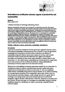
2.3 Laboratory test arrangements Laboratory tests were performed by Vahanen Oy that ordered the tests from Tampere University of Technology (TUT). Three test walls were assembled in total – Concept B1, Concept 2 and Concept T1b. Concept B1 by Vahanen The test was conducted to study the building physical behavior of a vacuum insulated brick wall. The test wall, shown in figure 2 was the same as concept B1 with the exception that vacuum panel used in the test had 10 mm EPS boards on both sides (Concept B1 uses 5 mm). In addition the ventilation space was 30 mm (Concept B1 uses 40 mm) and there was a porous wind barrier board on the left side of the vacuum insulation panel. A temperature difference of 40 °C was set across the wall. Studies also included a version of the wall that had no ventilation space but all the same construction layers. Thermocouples were set up between construction layers and in the ventilation space.
Figure 1. Concept B1 by VAHANEN test assembly.
27
2. Methodology
Figure 2. Concept B1 by VAHANEN, vacuum insulated test wall. Concept number 2 by Vahanen A full scale laboratory test was conducted to study the building physical behaviour of the Re-Solar concept. The test assembly is described in picture 3. The test wall consists of a glass façade, blinds with both white and dark surfaces, 70 mm air space, a 10.5 mm double layer of phase change material (PCM) panels, 100 mm EPS insulation and 200 mm lightweight aggregate concrete block. A heat exchanger was installed between the outdoor air and the air from the ventilation space. The outdoor climate chamber had two 1300 W infrared heaters and three 350 W halogen lamps to simulate heat radiation from the sun. Radiation intensity was approximately 210 W/m2 from noon to early evening and 10–20 W/m2 on other times. Outdoor temperature varied between -1.5 °C–10 °C and indoor temperature between 20–21.2 °C. Air flow rates varied between 2–22 dm 3/s in both cycles. Temperature was measured from the air space, at six depths of the wall, from the PCM-panels and from the ventilation channels. The Air flow rate was measured from the air space and ventilation channels. Pyranometer measured radiation intensity on the façade.
28
2. Methodology
Figure 3. Test wall assembly of the Re-Solar concept, an example of temperature, air-flow rate and radiation intensity values in the test.
Figure 4. Blinds installed behind the glass façade (left) and PCM-panels at the building phase of the wall (right). Concept T1b by Vahanen A full scale laboratory test was conducted to study the building physical behaviour of a thermal plastered concrete sandwich wall. The structure of the test wall was 100 mm concrete, 300 mm rockwool insulation, 5–10 mm plastering and silicone resin layer (water repellency). Test wall was divided to two parts, one with normal plastering (protective pore ratio 0.36) and other with weaker plastering (protective
29
2. Methodology
pore ratio 0.21). Weaker plastering was made by adding 26% more water than was instructed by the manufacturer. Temperature and relative humidity was measured from the insulation layer. Water was added to the insulation layer directly a total of 3.6 kg in one month. Water was added indirectly with 300 x 300 x 100 mm3 wet concrete shells that were installed upon the concrete wall and heated with two halogen lamps. The final 8 day phase of the test with spraying irrigation (rain water) included temperatures cycles of +30 °C and -20 °C that lasted 2 hours each. Test assembly is similar to picture 1 but the relative humidity in the indoor air was not measured due to a probe failure. Relative humidity in the outdoor varied between 75–78%.
Figure 5. Concept T1b by VAHANEN, thermal plastered test wall at building phase.
2.4 Life cycle assessment and life cycle costing Environmental impact and life cycle costs were assessed for 17 refurbishment concepts proposed by the SME partners of the SUSREF project. The assessment considered residential buildings and different refurbishment options; existing building type, level of insulation and building location, insulation type used in refurbishment concept, insulation thickness, and local energy type for heating. The environmental impact assessment focused on the impact of non-renewable energy (energy transmission through the wall and energy consumption of refurbishment materials), non-renewable raw materials (from energy production
30
2. Methodology
and refurbishment materials) and released greenhouse gases and thus carbon footprint. The main parameters for the LCA and LCC calculations were: U-values for existing walls Target U-values Thermal conductivity for used materials Heating degree days Basic renovation cost Extra renovation cost Heating cost Environmental loads for materials used Environmental loads for energy types. The LCA were made according to the following assumptions: Calculations made for a life span of 20 years Pre-defined cites (with specific heating degree days) represent the climatic zones Main heating energy types are gas (for central and eastern Europe), district heat (Finland) and electricity (Nordel) For existing wall no construction materials is considered only impact from heating is calculated Impact from heating is calculated as the heat flux through the wall. For energy calculations heating degree days for different location, based on +18 °C, have been used, except in the Nantlle Valley, where the only available data was for +15 °C Life cycle assessment for material and energy types uses general information about their production In some refurbishment cases, with new and advanced materials, life cycle assessment results were not known and thus not included in the energy, raw-material- and carbon footprint calculations. In these cases result contains only LCA from heat flux through the wall. The assessment method is described in detail in D3.5 (Assessment of refurbishment concepts of concrete sandwich elements and windows in Finland) of SUSREF.
31
3. Concept B1 by VAHANEN
3. Concept B1 by VAHANEN Brick wall with ventilated air gap
Multi-rise buildings Single family dwellings
Lime-sand brick wall
Dfc
This concept has been developed for buildings constructed during the era ca. 1950 to 1970 when brick was a major material in facades. During this time mineral wool was the popular insulation material. Solid brick walls usually have good durability; the material is robust and needs little maintenance. However, bricks are vulnerable to freeze-thaw phenomena, particularly if they have defects in their frost resistance (i.e. lacking protective pore structure or strength). Furthermore, water may soak into the brick and underlying thermal insulation materials causing notable loss of thermal insulation capacity. Present day brick materials are more reliably protected against frost damages. However, capillarity in bricks remains a material property and needs to be considered. Here, a concept solution of a brick wall with a ventilation gap and a vacuum insulated panel is presented. The refurbishment method requires a proper consideration of building physics and careful assembly of an undamaged vapour barrier. Indeed, the care of water and humidity issues is essential. In the case of ventilated walls, when the insulation layer is connected to the wall behind the ventilation layer (to the inner side of the gap), the wall generally remains dry.
32
3. Concept B1 by VAHANEN
Cross sections of existing and refurbished wall
Rationale and market potential The renovation method used in this concept is structurally heavy, and can take place only in certain circumstances. In southern Finland there are lots of houses and schools which were constructed during 1950–1970 using this construction type. In most cases the facades cannot be changed, so the only way to remove the contaminated insulation layer and improve the structure is to remove the outer brick layer. The use of a vacuum insulated material is also studied in this concept. At the moment, the price of the material is too high for common use but it could be used in special cases where the insulation layer has to be thin. The gap behind the exterior brick layer is only suitable for ventilation in cold and dry climate zones. Brick walls usually suffer from some level of water penetration. Therefore, the insulation used between the brick layers may have been exposed to water and thus lost the majority of its thermal properties. This, in turn, affects the energy performance of the building. Furthermore, the existing wet insulation layer usually contains mould growth and microbes that are brought to indoor air. The insulating performance of vacuum insulated panels is 5 to 8 times better than conventional insulation. Therefore a high level of energy efficiency can be achieved with minimal disruption to the size of the external wall. Application guidelines Expansion joints, ventilation spaces, reinforcement and masonry ties will be installed according to the construction plans. Ties are placed to the vertical seams of vacuum insulation panels. Mortar fins must be removed from the ventilation space.
33
3. Concept B1 by VAHANEN
The seams between the rigid mineral wool insulation board and the wind barrier coating must be taped according to the instructions of the supplier. This is required as the vacuum insulation panel alone doesn’t work as a wind barrier in the structure. The rigid board also acts as a fire barrier for the ventilated space and the vacuum panel. EPS insulation sheet on both sides of vacuum insulation panel: Fastening is made from adhesive mortar throughout to the base. Old interior concrete or brick envelope: Penetrations and interfaces are air sealed. The external surface should be smoothed so there are no sharp surfaces which could affect the installation of the vacuum panels. Sealing of window and door frames External sealant First, apply an external polyurethane foam outer sealant strip to the frame gap. This is permanently tight against driving rain but still ‘open’ to allow water vapour to escape to the external atmosphere. Intermediate sealant The gap around the frame is sealed with elastic polyurethane foam. Sealing should be homogenous and air-tight. Sealing is completed from inside, before exterior and interior architraves are installed. If necessary, foam may be reapplied at a later stage. The foam should fill the gap to 2/3 of the depth of the gap measured from the interior surface. Internal sealant After the foam has dried, the interior seam between the frame and wall is sealed using an internal foam sealant strip and an elastic sealant. Before installing the sealant strip, make sure the polyurethane foam layer is thick enough and then set the strip on fresh foam after the foam has stopped expanding. The sealant strip should be as deep as the gap is wide. The elastic sealant is then applied to close the gap, flush to the internal wall surface. Architraves are installed after sealing. The edges of architraves should be pressed tightly to the window/door frame and wall. Small gaps can be sealed with an acrylic sealant. In cases where intermediate sealants already exist, they should be examined to determine their suitability. These should either remain or be replaced, depending on their condition.
34
3. Concept B1 by VAHANEN
Ventilation upgrades required Fresh air inlets are needed because of the improved air tightness of the exterior wall. Inlets can be integrated into the windows or installed to holes drilled through the walls. Exhaust ventilation should be considered.
3.1 Buildability Brick wall construction is an elementary building technique for many construction workers throughout Europe and is therefore a refurbishment technique which generally requires minimal further education. Furthermore, only basic building tools are required.
3.2 Known problems The thickness of the exterior wall structure will increase (if carried out with traditional insulation materials like mineral wool). There is also a need to find a suitable thickness for the outer brickwork that does not allow water penetration. Failure of vacuum panels is usually caused by careless handling and transportation. Without protection the envelope is highly sensitive to mechanical impact, especially to point loads.
3.3 Maintenance and disturbance The following maintenance procedures are required: Mortar – Mortar should be re-pointed every around every 25 years, depending on exact geographical location. Efflorescence – A white, salty deposit on the brick surface is a sign of water penetration. This can be cleaned with a stiff brush. If hard deposits have formed, a chemical cleaner is needed. During construction, the interior skin of the external wall remains, so there should be no physical disturbance to tenants, only noise pollution.
3.4 Performance values used in assessment Material
Thickness, mm
Brick Mineral wool Vacuum insulation panel
125 30/100 0.02–0.03
Properties Bulk Porosity density [-] [Kg/m3] 60 0.95 1900 0.24
35
Specific Heat. Capacity [J/kg K] 850 850
dry
[W/mk] 0.6 0.04 0.008
µdry [-] 1.3 10
3. Concept B1 by VAHANEN
3.5 Durability assessment B1 by VAHANEN Dfc Climate Zone (Jyväskylä) Thermal Performance Description
Values
Transmission coefficient
Original: 0.32 W/(m2K) Refurbished: 0.19; 0.21; 0.24
Thermal bridge effect Conclusion
Unit
-
-
Good performance
Moisture Performance Annual moisture accumulation
-
kg/m2/year
Risk for frost damage T < 0 °C, RH > 95%
Results were not reliable
h/year
Risk for mould, corrosion T > 0 °C, RH > 80%
Results were not reliable
h/year
Risk for condensation, algae, decay Results were not reliable T > 0 °C, RH > 95%
h/year
Conclusion Indoor Climate Lowest indoor surface temperature
18.01–18.66
Conclusion
Very good performance
°C
Overall conclusion Under normal weather conditions and with correct maintenance, bricks can last for a century or more. However, they are vulnerable to moisture, especially when exposed to freeze/thaw cycles. A significant amount of water can pass through brick walls, and can therefore penetrate to the interior structures, in this case to the insulation and interior brick layer. To improve the function of the original wall structure, the ventilation and drainage gap was added to the wall structure and the old mineral wool insulation was changed to a more energy efficient insulation (vacuum insulation panel). A ventilation gap enables the outer bricks to dry after rain and decreases the possibility of moisture damage. Because the vacuum insulation panel works as a vapour barrier, moisture and heat flow cannot move through the structure. Drying out of interior brick work occurs only inwards, while the external structure dries only outwards.
36
3. Concept B1 by VAHANEN
In external walls, one of the main moisture sources is driving rain. If a building is tall, has small eaves, and is located in a windy, open area then it will be more susceptible to the stresses of driving rain. In Finnish climate conditions, wall structures are often exposed to this rain and in order to allow the structure to dry there must be a ventilation gap between the outer brick work and wind barrier. Moreover, once the wall is dry, the risk of mould growth is reduced in a ventilated wall structure. Simulation results show that changing the old mineral wool to new more energy efficient insulation will reduce the heat flow through the structure. In addition, when the thickness of new insulation is increased the energy efficiency of the wall structure improves. However, the improvement is not prominent when the thickness of vacuum insulation panel is increased. The results of TOW calculations indicate that repairing the original wall will increase the possibility of frost formation on the outer brick surface. The results of the ventilated structure calculations are not reliable because the actual air movement in the ventilation gap cannot be taken into account in the calculations. The simulations of refurbished structures correspond to the structure without a ventilation gap. In the case of ventilated walls, the insulation layer, which comes after the ventilation layer, is generally dry. Significant risks The risk of condensation is very high on the outer surface of the vacuum insulation panel. Thus, the risk of biological growth on the exterior surface of the panel must be kept in mind when an external wall is repaired. The aluminum foil on the vacuum insulation panel surface is sufficiently tight to prevent air from the structure moving into the indoor environment. Thus, the risk of bad indoor air is very low as long as the vacuum insulation panel is not broken. When the outer layer of the external wall is removed during the repair work, it is very important that the interior layer of the external wall is covered with a weatherproof shelter to avoid significant damp. Shelter can be removed once the outer brick work has been done. If the interior brick work gets wet the structure can be damaged affecting indoor air quality. In Finland the ventilation gap in this kind of wall structure is essential.
3.6 Results from the laboratory tests The results showed that the air movement in the ventilation space is significantly weakened due to the reduced heat flow from the inside of the wall. In fact, air moved downwards in the air space which indicates that the stack effect was weak. The temperature was 1 °C lower in the upper part of the air space than in the lower part. During testing, air movement was determined by the fan in the outer test room, whereas in an actual building air movement in the ventilation space would be determined by wind changes. This reduction in air movement can be a
37
3. Concept B1 by VAHANEN
problem in a wall facing north where there is limited solar radiation energy to generate air movement. In general, better insulation reduces air movement in the air space which must be taken into account in the drying ability of the wall. The temperature was about 1 °C higher on the warm side of the vacuum insulation panel in the non-ventilated wall compared to the ventilated wall. This means ventilation of the structure has no major effect on the heat flow of the wall. The temperature was 0.3–0.5 °C lower in the joint of two vacuum panels than in the center of a panel. In practice, the continuity of the vacuum panels in the envelope is more important in avoiding cold bridges. The temperature was 4– 6.5 °C lower behind a broken vacuum insulation panel compared to the intact one. The largest difference (6.5 °C) was measured in the wall with a ventilation space in the joints of the panels.
Figure 6. Thermal image from the inside points out the broken insulation in the test wall. A broken vacuum insulation panel has a thermal conductivity of 0.022 W/mK measured with heat flux plates. The manufacturer gives a value of 0.019 W/mK for broken insulation. Breaking of the panels causes additional heat loss but the effect is restricted to the broken panel only. The surface temperature inside the wall is lowered to 17 °C from 20 °C in the middle of the panel with outer temperature -20 °C. Risk of condensation is negligible and requires an indoor relative humidity of 80% in this case.
38
3. Concept B1 by VAHANEN
Figure 7. Intact and broken vacuum insulation panels. When choosing vacuum insulation panel sizes one should consider the limiting effect of small panels on increased heat transfer but also the additional joints and possible air leaks caused by small panels. Despite the protecting EPS-boards, a vacuum insulation is vulnerable to strikes and breaks easily. A vacuum insulation is either broken or intact. There is no such thing as half broken vacuum insulation. Based on a bending test of vacuum panels the vacuum can tolerate a bending of 10° but breaks after that. The protecting EPS boards already break at this angle but probably don’t lose their insulating properties. The breaking of a vacuum (picture 3, right picture) is difficult to notice during construction. The damage was visible when checked from the vacuum cover after many hours. Damage can be seen also from the swelling of the panel which was in the center of the panel about 10 mm. Moisture behaviour of the wall Vacuum insulation is a vapour tight layer so water vapour diffusion is totally blocked across the insulation. This is why vacuum insulation should not be used in outer parts of the wall at least without a moisture transfer analysis. Another consequence of the vapour tightness is that when used inside of the old structure there is no need for separate vapour barrier. In general, the moisture behaviour of vacuum insulated refurbished structures should be investigated thoroughly in the future.
3.7 Impact on energy demand for heating and cooling Refurbishment will reduce energy demand for heating.
3.8 Impact on renewable energy use potential No impact.
39
3. Concept B1 by VAHANEN
3.9 Environmental impact The methodology of this assessment is discussed in the introduction. Specific assumptions made in conducting this LCA are as follows: The assessment considers all materials used in the refurbishment. New external façade with sand lime brick, 30 mm rigid mineral wool and 20 mm vacuum insulation covered on both sides with EPS insulation (2 x 5 mm). No LCA data was found for vacuum insulation so this calculation assumes that all 30 mm insulation is EPS. When LCA data for vacuum insulation is available, then a new calculation should be completed. For the existing wall, no construction materials are considered, only the impact from heating is calculated. U-value used for the existing wall is 0.32 W/m 2K. U-value used for the new concept is 0.24 W/m2K. 180
Carbon footprint, kg CO2 eq/wall-m2/20 year
160 140 120 100 CF heating, Helsinki
80
CF, material
60 40 20 0 Existing, Helsinki
Ren. New sand lime facade +30 mm board+EPS, Helsinki
Figure 8. Carbon footprint for existing-and refurbished walls. Existing wall analysis considers only carbon footprint from heating use. Heating type for Helsinki was district heating.
40
3. Concept B1 by VAHANEN
2 500
Fossil energy, MJ/wall-m2/20 year
2 000 1 500 from heating 1 000
from material
500 0 Existing, Helsinki
Ren. New sand lime facade +30 mm board+EPS, Helsinki
Figure 9. Fossil energy consumption for existing and refurbished walls. Heating type for Helsinki was district heating.
Non renewable raw material kg/wallm2/20 year
350 300 250 200 from heating
150
from material
100 50 0 Existing, Helsinki
Ren. New sand lime facade +30 mm board+EPS, Helsinki
Figure 10. Non renewable raw-material consumption for existing- and refurbished walls. Heating type for Helsinki was district heating.
41
3. Concept B1 by VAHANEN
3.10 Indoor air quality and acoustics Indoor air quality will be improved if a contaminated insulation layer is removed. Sealing will improve air-tightness.
3.11 Structural stability and fire safety Stability is improved because when damaged brickwork is replaced. Careful demolition work is required. Changes in Fire safety will be dependent upon local regulations. Usually the ventilation gap should be closed or at least restricted between floors. There are also local demands on the outer surface of the wind barrier.
3.12 Aesthetic quality and effect on cultural heritage A wide variety of brick types are available so the quality of brick can be chosen according to budget and location. In some cases recycled bricks can be used. Original brickwork can be replaced with same type and colour to preserve the existing look of the façade if required.
42
4. Concept number 2 by Vahanen
4. Concept number 2 by Vahanen Re-Solar
Multi-rise buildings
Sandwich element panels
Dfc, Csa
This concept is highly innovative. It presents a solution which offers more than just shelter as the wall is made active in the generation and conservation of energy. The structural solutions allow the collection solar energy for heating and can also protect the building from overheating. This allows a more constant indoor temperature and saves energy costs by utilising solar energy. Currently the solution is beneficial in southern climates but it could be utilized in more northern areas by enhancing the energy collection and retention capacity. This may be done by adding phase changing material to the external surface of the insulation material (i.e. to the mineral wool). The materials utilized in the concept are fairly familiar and have demonstrated durability – the main innovation is in the structural solution.
43
4. Concept number 2 by VAHANEN
4.1 Fixing and exploded view of Re-Solar Concept
44
4. Concept number 2 by VAHANEN
4.2 Ventilation and air supply details
45
4. Concept number 2 by VAHANEN
4.3 Rationale and market potential There is a need to research and push the boundaries of what is possible with current technology with regards to energy efficient refurbishment of buildings. This is an innovative refurbishment concept which is intelligent and can recognise when the indoor air requires additional heating or cooling. In the long term this would hopefully reduce the energy usage of the building. It also takes advantage of natural renewable heating resources (sunlight) to pre-heat the outdoor air supply, which is used to heat the building. This system is
46
4. Concept number 2 by VAHANEN
also able to provide fresh, filtered air to the building regardless of the weather conditions. Since the new cladding creates a waterproof envelope and covers the wall structure, the existing windows can remain, which partially reduces costs and material consumption compared to basic façade renovation with window replacing. Southern climate zones in specific cases, where there is need to improve ventilation and indoor climate. It also provides an opportunity to renew the exterior architecture of a building. Installation is quick with prefabricated elements.
4.4 Application guidelines Glazing should be south facing and supported by a metal frame (steel or aluminium) which is fixed to the bearing structure of the existing building. Venetian blinds are installed in the air gap between the glazing and the new insulation layers. There is a removable panel located in the glazing which is used to access the blinds for maintenance. Exact fixing details for phase changing material boards vary depending on manufacturer and the complexity of the existing external surface. Phase Changing Material is installed directly behind the blinds and its purpose is to store the excess heat which will be created when sunlight penetrates the external glazing. It will then release this heat to the structure when the external temperature falls. This should help to reduce temperature peaks in the structure. Insulation slabs should be laid to bond with each other, particularly at the corner of the building, window corners and door heads. Windows, corners and doors must be insulated using a whole slab to prevent possible cracks and cuts in the corner. Insulation is to be fixed to the external surface of the existing building with polyethylene plugs 3–4 pcs/m². The existing wall structure will be prepared so that it is in a good condition to receive the new layer of thermal insulation. New supply air units should be installed according to manufacturer’s instructions. Ventilation upgrades required See the previous diagrams.
4.5 Buildability Similar glass frame structures are currently being built in office buildings. Prefabricated elements are quick to install.
47
4. Concept number 2 by VAHANEN
4.6 Maintenance and disturbance The level of required maintenance depends on the materials used. Aluminium and glass require very little maintenance. Windows and blinds need to be cleaned and filters must be replaced twice a year. There is likely to be a high level of disturbance to tenants. HVAC equipment has to be installed in the interior spaces. Furthermore, fixing glazing to the existing façade will require large-scale structural work. This will result in noise and air pollution.
4.7 Performance values used in assessment An overall U-value of 0.25 W/m2K. Preliminary value based on the concept’s bare raw materials. There will be a difference when the constant air flow in the façade is taken into consideration in the calculation.
4.8 Durability assessment Although the concept is experimental, the basic material components have a proven history of good durability (glass, steel, aluminium). Moreover, the new glazed surface will protect the old structure. Cross flow heat exchanger life expectancy is more than 10 years. The wall structure of this concept has been simulated with Comsol simulation software. It has been discovered that its use would not be financially viable in Northern Climate zones like Finland. This kind of wall is more suitable to countries with warmer climates e.g. South European countries. Simulation results shows that in Northern European countries phase transformation material should be added to the mineral wool external surface. Conversely, in Southern European countries (e.g. Spain), the phase transformation material may not be necessary.
4.9 Impact on energy demand for heating and cooling The method will reduces the building’s energy demand by using renewable solar energy. The concept can be used for cooling as well by installing reflective blinds. Using Phase changing materials in the structure introduces active temperature management to the building.
4.10 Environmental impact The methodology of this assessment is discussed in the introduction. Specific assumptions made in conducting this LCA are as follows:
48
4. Concept number 2 by VAHANEN
Refurbishment concept considers materials used: glazing, venetian blind (expected to be aluminium), phase change material (expected to be gypsum) additional insulation (100 mm PUR). Concept also requires an air supply unit, heat exchanger and ducts, which are not taken into account. U-value used for the existing wall is 0.44 W/m 2K. U-value for the concept with 100 mm additional insulation is 0.25 W/m2K. This is calculated according to the wall structure. When evaluating the actual energy demand for heating, it is also necessary to consider the impact of natural heat sources (sunlight), which are used in this concept to pre heat the outdoor air supply. The calculations in this assessment assume lowered U-values of 0.21 W/m2K in Finland and 0.15 W/m2K in Barcelona. This reduces annual energy demand by 4 kWh/m2. However, this estimation does not account for the true benefits of providing pre heated air and this should be calculated in a real life scenario. Nevertheless, modelling was completed for two scenarios: “Ren1” is based only on the use of raw materials modelled in the LCA while “Ren2” attempts to estimate the impact of the pre-heated air.
CF heating
250
Carbon footprint, kg/wall-m2/20 year
CF, material 200 150 100 50 0 Existing Ren1 Ren2 Barcelona Barcelona Barcelona
Existing Helsinki
Ren1 Helsinki
Ren2 Helsinki
Figure 11. Carbon footprint for existing-and refurbished walls. Existing wall considers only carbon footprint from heating use. Heating type for Helsinki was district heating, and for Barcelona it was gas.
49
4. Concept number 2 by VAHANEN
4 500
from heating
4 000
from material
Fossil energy, MJ/wall-m2/20 year
3 500 3 000 2 500 2 000 1 500 1 000 500 0 Existing Ren1 Ren2 Barcelona Barcelona Barcelona
Existing Helsinki
Ren1 Helsinki
Ren2 Helsinki
Figure 12. Fossil energy consumption for existing and refurbished walls. Heating type for Helsinki was district heating and for Barcelona it was gas. from heating
Non renewable raw material, kg/wall-m2/20 year
120
from material
100 80 60 40 20 0 Existing Ren1 Ren2 Barcelona Barcelona Barcelona
Existing Helsinki
Ren1 Helsinki
Ren2 Helsinki
Figure 13. Non renewable raw-material consumption for existing- and refurbished walls. Heating type for Helsinki was district heating and for Barcelona it was gas.
50
4. Concept number 2 by VAHANEN
4.11 Life cycle costs
4.12 Indoor air quality and acoustics Improves indoor air quality, incoming air is filtered and warmed. The exterior structure reduces effect of outdoor noise.
4.13 Structural stability The structural stability should be studied individually on a building by building basis. The new structure should be fixed to the load bearing structure of the original building.
4.14 Fire safety The structure is closed between apartments so that fire cannot spread horizontally or vertically.
51
4. Concept number 2 by VAHANEN
4.15 Aesthetic quality and effect on cultural heritage The refurbishment changes the appearance of the building façade dramatically. Skilful architectural work is needed to ensure an acceptable appearance. Therefore, it is not an ideal solution for use on buildings with historical value due to the dramatic alteration of the building façade.
52
5. Concept T1a by Vahanen
5. Concept T1a by Vahanen ETICS applied to Sandwich element
Multi-rise buildings
Sandwich element panels
Dfc
This concept is fairly familiar in most Northern European countries; it is relatively simple, structurally safe, and fairly easy to construct with commonly available materials. The sandwich elements are abundant in Northern European markets, including extensive export markets in Russia. Specifically, if the old outer surface of the external wall is in a bad condition, then this concept is favourable. The energy saving potential of the concept is dependent upon the thickness of the insulation material used in the project. Thus, design phase energy saving calculations are simple to complete.
53
5. Concept T1a by Vahanen
5.1 Cross sections of existing and refurbished wall
5.2 Rationale and market potential A three layer concrete wall structure has been very common in all European countries since 1960. The refurbishment method is well developed and the technology is widespread. The thick mineral wool layers examined in this concept are relevant in Northern European countries. Mineral wool is commonly used in more Easterly European Countries and in Russia because of fire safety regulations. The refurbishment method can be used for solid concrete block walls and also for panel type walls. The method reduces heating costs during winter, but keeps the outer shell of the building from heating up during the summer. Thus, the method can lower the building’s energy consumption. The building façade will get a new aesthetic design and net living space will be preserved. The building’s substructure is preserved as the method provides moisture protection and enables reduced temperature fluctuations. This is a widely used refurbishment technology in Finland, typically using mineral wool because of fire safety regulations that vary locally.
54
5. Concept T1a by Vahanen
5.3 Application Guidelines Finishing render must be set and dry for a minimum of 7 days before paint application. Use adhesive strips to create a boundary line between two shades of paint. Primer may be applied after the adhesive has dried out for at least 2 days. Primer must be thoroughly dried out (min. 24 hours) before render application. Application and exact thickness depends on the selected granulation and the grain of the façade. The thickness of the layer is usually equal to the average grain size of the mortar. The finishing layer should be floated while still wet. While drying out, the façade must be protected against strong sunlight, rain and wind. At low temperatures and high humidity, the mortar will take longer to dry. Before applying the first layer of adhesive, smooth and reinforce all corners of the building and the corners of the windows and doors using a corner batten reinforcing mesh. To prevent cracks, stick the strips of reinforcing mesh of at least 300 x 200 mm above the corners of the windows and door heads and openings, at an angle of 45°. Then insert reinforced mesh into the freshly applied adhesive with min 100 mm overlap. When the adhesive with inserted mesh dries out, cut off the surplus mesh. Make sure that insulation slabs are laid to bond with each other, particularly at the corner of the building, window corners and door heads. Windows, corners and doors must be insulated using a whole slab to prevent possible cracks and cuts in the corner. Insulation is fixed to the inner concrete panel with polyethylene plugs 3–4 pcs/m² 24 hours after insulation is fixed to the wall. Adhesive is applied along the edge of the insulation slab and six dabs spread out over the slab. Apply with a trowel and ensure that enough adhesive is used so that it is firmly and evenly spread along all the edges of the slab. Surface irregularities can be removed with rough sand paper. Structural stainless steel anchors are used to secure the outer shell to the inner bearing shell if necessary, to ensure stability. 4–5 steel anchors should be used per panel. Extra care should be taken when sealing the indoor panel so that the seams are air-tight. This prevents any contaminants from the existing wall transferring to the indoor environment. Sealing of window and door frames External sealant First, apply an external polyurethane foam outer sealant strip to the frame gap. This is permanently tight against driving rain but still ‘open’ to allow for water vapour to escape to the external atmosphere.
55
5. Concept T1a by Vahanen
Intermediate sealant The gap around the frame is sealed with elastic polyurethane foam. Sealing should be homogenous and air-tight. Sealing is completed from inside, before exterior and interior architraves are installed. If necessary, foam may be reapplied at a later stage. The foam should fill the gap to 2/3 of the depth of the gap measured from the interior surface. Internal sealant After the foam has dried, the interior seam between the frame and wall is sealed using an internal foam sealant strip followed by an elastic sealant. Before installing the sealant strip, make sure the polyurethane foam layer is thick enough and then set the strip on fresh foam after the foam has stopped swelling. The sealant strip should be as deep as the gap is wide. The elastic sealant is then applied to close the gap, flush to the internal wall surface. Architraves are installed after sealing. The edges of architraves should be pressed tightly to the window/door frame and wall. Small gaps can be sealed with an acrylic sealant. In cases where intermediate sealants already exist, they should be examined to determine their suitability. Then they can either remain or be replaced, depending on their condition. External and Internal sealants can then be applied where necessary. The same procedure applies for all window and door jambs. Ventilation upgrades required Fresh air inlets are needed because of the improved air tightness of the exterior wall. Inlets can be integrated into the windows or installed to holes drilled through the walls. Exhaust ventilation should be considered.
5.4 Buildability Thermal plaster application is a common practice throughout Europe and the technique does not vary greatly from traditional plastering. Only basic building tools are required.
5.5 Known problems related to refurbishment method Algae growth may occur on the surface of plaster and cracks and holes can also appear due to seasonal air temperature changes. A safe level of insulation thickness needs to be determined. Joints around windows and doors are potentially susceptible water leakage if they are not sealed correctly.
56
5. Concept T1a by Vahanen
5.6 Maintenance and Disturbance Care should be taken during construction to ensure that there are no gaps in the finished surface as this will encourage water penetration and may require remedial work. The entire structure of the external wall remains, so there should be no physical disturbance to tenants. Only the noise from construction may be an issue. Sealing from inside will cause temporary relocation of fixed furniture and plinths along the exterior wall.
5.7 Performance values used in the assessment Material
Thickness,
Properties
mm
Bulk density [Kg/m3]
Porosity [-]
Specific Heat. Capacity [J/kgK]
[W/mk]
Lime cement plaster
2
1900
0.24
850
0.8
19
Mineral wool
80–300
60
0.95
850
0.04
1.3
Concrete
60–120
2300
0.18
850
1.6
180
57
dry
µdry [-]
5. Concept T1a by Vahanen
5.8 Durability T1a by VAHANEN Dfc Climate Zone (Jyväskylä) Thermal Performance Description
Values
Unit
Transmission coefficient
Original: 0.44 W/(m2K) Refurbished: 0.17; 0.21; 0.28
Thermal bridge effect
-
Conclusion
Good performance
-
Moisture Performance kg/m2/year
Annual moisture accumulation
-
Risk for frost damage T < 0 °C, RH > 95%
Original*1:271; Refurbished*1: h/year 1679–1722
Risk for mould, corrosion T > 0 °C, RH > 80%
Original*2: 4777; Refurbished*2: 3483–3668
h/year
Risk for condensation, algae, decay Original*2: 1223; Refurbished*2: 2418–2533 T > 0 °C, RH > 95%
h/year
Conclusion
Values are significantly high
Indoor Climate Lowest indoor surface temperature
17.31 to 19.1
Conclusion
Very good performance
°C
1
* : outer surface of structure 2
* : insulation outer surface (original)/ external insulation outer surface (refurbished).
Overall conclusions One of the most critical sources of moisture in all facades is strong driving rain. The strain of driving rain on a facade and its harmful effects can be decreased using large overhanging eave structures. The thermal capacity of concrete sandwich walls is improved by adding a new insulation layer onto the old wall structure. As a result of adding a new insulation layer, the relative humidity of the concrete sandwich wall changes slightly. Compared to the original wall, the simulation results show that adding the new mineral wool layer onto the old wall structure significantly reduces the heat flow through the structure. However, when the thickness of the new insulation layer is increased the energy efficiency of the wall structure does not increase significantly. According to the TOW calculations, the risk of frost formation on the outer thermal insulation surface is significant in the case of repaired external walls. When the outer insulation layer is increased the possibility of frost formation also
58
5. Concept T1a by Vahanen
increases. In addition, the calculations show that there is a risk of mould growth in refurbished external walls. In the case of refurbished walls, mould growth is smaller when the additional insulation layer is increased. Because of the high RH in the outer concrete layer (original external wall), there exists a significant risk of corrosion growth in the reinforcement. Theoretically this could happen in conditions where RH > 55% (carbonization of concrete booster causes corrosion of reinforcement). Significant Risks Mineral wool can survive most negative factors for a long period of time. However, plaster can be damaged easily depending on the quality of the compound and the quality of plaster mixing. In order that mineral wool can survive, plaster and joints of external wall must not be damaged. If the protective plaster is damaged, then moisture can penetrate to the mineral wool which would result in a reduction of Uvalue. Before repairing the external wall, the condition of the old exterior concrete cladding must always be checked. The load bearing capacity of old concrete walls can be very poor. If only small damages have been found in the concrete cladding, then the repair can be executed. The risk of damage to the concrete cladding is reduced with a new insulation and plaster layer. Results from the laboratory tests The experiment was made with various boundary conditions. The best result from the ratio of solar energy transferred to the inside air was 50% from the radiation intensity. The minimum ratio was 30%. This ratio is larger with greater air flow rates. The amount of utilized radiation energy decreases significantly (roughly 20– 30%) if the surface of the blinds is white. With no blinds at all, the utilized energy amount decreases even further. The best operation of the concept would include automatic turning of the blind so that the dark surface of the blinds would turn towards the phase change panels right after suns radiation intensity decreases significantly. The phase change panels acted as thermal storage and prolonged the heating effect of the heat exchange process. Heat exchange was effective for at least three hours after radiation energy on the façade has ended. In the test, the air flow channels were quite narrow which probably caused higher flow losses than would have occurred in a real refurbishment structure. In a similar structure to the one used in this test but without Re-Solar (200 mm lightweight concrete block, 100 mm EPS and plastering) conduction heat loss would be 3.5–6 W/m2, a total of 0.5 kWh in a day (Wufi calculation with similar boundary conditions) but in Re-Solar heat exchange process transferred 1.8 kWh energy to the indoor in a day when radiation intensity was 210 W/m2 for 6 hours. In a normal wall radiation energy is not utilized this effectively because of the thermal mass of the wall. The results apply only to the test wall. A field test in a
59
5. Concept T1a by Vahanen
real building and a moisture technical analysis are necessary in the future to analyze the possibilities of this refurbishment method. 25
300
from air space
20
200
to indoor
15
Radiation intensity
150
100
10
50
Radiation intensity [W/m2]
back to air space from outdoor
Temperature [degC]
250
5 0
0 12:00
18:00
-50 0:00
Figure 14. An example of temperatures before and after the heat exchange.
5.9 Impact on energy demand for heating and cooling The concept will reduce energy demand compared to original.
5.10 Impact on renewable energy use potential No impact.
5.11 Environmental impact The methodology of this assessment is discussed in the introduction. Specific assumptions made in conducting this LCA are as follows: Refurbishment concept considers all materials used and three insulation levels: 100 mm, 200 mm and 300 mm mineral wool. Calculations are based on a thickness of 25 mm for the façade render with float. The U-value for the existing wall is 0.44 W/m2K.
60
5. Concept T1a by Vahanen
The U-value for the concept with 100 mm additional insulation is 0.21 W/m2K. The U-value for 200 mm of additional insulation is 0.14 W/m2K. The U-value for 300 mm of additional insulation is 0.10 W/m2K.
Carbon footprint, kg CO2 eq/wall-m2/20 year
250 200 150 CF heating, Helsinki
100
CF, material
50 0 Existing, Helsinki
Renovated (100 mm)
Renovated (200 mm)
Renovated (300 mm)
Figure 15. Carbon footprint for existing-and refurbished walls. Existing wall considers only carbon footprint from heating use. Heating type for Helsinki was district heating. 3 500
Fossil energy, MJ/wall-m2/20 year
3 000 2 500 2 000 from heating
1 500
from material
1 000 500 0 Existing, Helsinki
Renovated (100 mm)
Renovated (200 mm)
Renovated (300 mm)
Figure 16. Fossil energy consumption for existing-and refurbished walls. Heating type for Helsinki was district heating.
61
5. Concept T1a by Vahanen
Non renewable raw material, kg/wall-m2/20 year
120 100 80 60
from heating
40
from material
20 0 Existing, Helsinki
Renovated (100 mm)
Renovated (200 mm)
Renovated (300 mm)
Figure 17. Non renewable raw-material consumption for existing- and refurbished walls. Heating type for Helsinki was district heating.
5.12 Life cycle costs
62
5. Concept T1a by Vahanen
5.13 Indoor air quality and acoustics Internal sealing will prevent any contaminants from the existing wall from transferring to the indoor environment.
5.14 Structural stability and fire safety Any damaged fixings on the existing exterior panel can be secured by new fixings. Fires safety impacts are dependent upon local regulations.
5.15 Aesthetic quality and effect on cultural heritage An almost infinite amount of colours are available for thermal plastering. Providing good quality workmanship is used to create the desired finish then the refurbishment method should enhance the external appearance of a building. However, the added thickness of the structure can cause problems with windows, doors, eaves, balconies etc. If used to renovate an apartment building with a plaster finish then it is acceptable. If the plaster covers up some different existing material then it is necessary to consult local planning conditions.
63
6. Concept T1b by Vahanen
6. Concept T1b by Vahanen ETICS applied to Sandwich element internal layer
Multi-rise buildings
Sandwich element panels
Dfc
This concept is familiar in most Northern countries; it is relatively easy to construct, structurally safe, and uses commonly available materials. The sandwich elements are abundant in the market areas of all Northern European countries, including the extensive export markets in Russia. In particular if the old outer surface of the external wall is in bad condition, this concept is favourable. The energy saving potential of the concept is dependent upon the thickness of the insulation material used in the project. Thus, design phase energy saving calculations are simple to complete.
64
6. Concept T1b by Vahanen
6.1 Cross sections of existing and refurbished wall
6.2 Rationale and market potential Reduces heating demand during winter, but keeps the outer shell of the building from overheating during the summer. Thus the building’s energy consumption is lowered overall. The building gets new aesthetic façade design and net living space is preserved. The building’s substructure is preserved as the method provides moisture protection and enables reduced temperature fluctuations. A three layer concrete wall structure is very common in all European countries. This concept requires the removal of the exterior panel and replacement of the insulation layer. The outer panel is removed if it is structurally damaged and the concrete has weathered beyond repair. This is estimated by laboratory tests. Growing concerns over indoor air quality provide the rational for the removal of existing insulation layers which often have mould growth and microbes. This is usual in Finland due to the casting technology which leaves the inner concrete panel surface very rough and makes tightly fixing insulation very difficult. The refurbishment method is well developed and the technology is widely spread. The thick mineral wool layers examined in this concept are highly prevalent in Northern European countries. Mineral wool is commonly used in more in Finland, Easterly European Countries and in Russia because of fire safety regulations, which vary locally. The refurbishment method can also be used for solid concrete block walls, but is not suitable for panel type walls which are predominantly found in Russia, and other Eastern European countries.
65
6. Concept T1b by Vahanen
6.3 Application guidelines Finishing render must be set and dry for a minimum of 7 days before paint application. Use adhesive strips to create a boundary line between two shades of paint. Primer may be applied after the adhesive has dried out for at least 2 days. Primer must be thoroughly dried out (min. 24 hours) before render application. Application and exact thickness depends on the selected granulation and the grain of the façade. The thickness of the layer is usually equal to the average grain size of the mortar. The finishing layer should be floated while still wet. While drying out, the façade must be protected against strong sunlight, rain and wind. At low temperatures and high humidity, the mortar will take longer to dry. Before applying the first layer of adhesive, smooth and reinforce all corners of the building and the corners of the windows and doors using a corner batten reinforcing mesh. To prevent cracks, stick the strips of reinforcing mesh of at least 300 x 200 mm above the corners of the windows and door heads and openings, at an angle of 45°. Then insert reinforced mesh into the freshly applied adhesive with min 100 mm overlap. When the adhesive with inserted mesh dries out, cut off the surplus mesh. Make sure that insulation slabs are laid to bond with each other, particularly at the corner of the building, window corners and door heads. Windows, corners and doors must be insulated using a whole slab to prevent possible cracks and cuts in the corner. Insulation is fixed to the inner concrete panel with polyethylene plugs 3–4 pcs/m² 24 hours after insulation is fixed to the wall. Adhesive is applied along the edge of the insulation slab and six dabs spread out over the slab. Remove any surplus adhesive from the previously attached insulation. Any surface irregularities can be removed with rough sand paper. Sealing of window and door frames External sealant First, apply an external polyurethane foam outer sealant strip to the frame gap. This is permanently tight against driving rain but still ‘open’ to allow for water vapour to escape to the external atmosphere. Intermediate sealant The gap around the frame is sealed with elastic polyurethane foam. Sealing should be homogenous and air-tight. Sealing is completed from inside, before exterior and interior architraves are installed. If necessary, foam may be reapplied at a later stage. The foam should fill the gap to 2/3 of the depth of the gap measured from the interior surface.
66
6. Concept T1b by Vahanen
Internal sealant After the foam has dried, the interior seam between the frame and wall is sealed using an internal foam sealant strip followed by an elastic sealant. Before installing the sealant strip, make sure the polyurethane foam layer is thick enough and then set the strip on fresh foam after the foam has stopped expanding. The sealant strip should be as deep as the gap is wide. The elastic sealant is then applied to close the gap, flush to the internal wall surface. Architraves are installed after sealing. The edges of architraves should be pressed tightly to the window/door frame and wall. Small gaps can be sealed with an acrylic sealant. In cases where intermediate sealants already exist, they should be examined to determine their suitability. Then they can either remain or be replaced, depending on their condition. External and Internal sealants can then be applied where necessary. The same procedure applies for all window and door jambs. Ventilation upgrades required Fresh air inlets are needed because of the improved air tightness of the exterior wall. Inlets can be integrated into the windows or installed to holes drilled through the walls. Exhaust ventilation should also be considered.
6.4 Buildability Similar techniques are being used in Finland and elsewhere in Europe. Indeed, thermal plaster application is a common practice throughout Europe and the technique does not vary greatly from traditional plastering. Furthermore, only basic building tools are required.
6.5 Known problems related to refurbishment method Algae growth is possible on the surface of plaster. Cracks and holes can also appear here due to seasonal air temperature changes. Therefore, a safe level of insulation thickness needs to be determined. Joints around windows and doors are potentially susceptible water leakage if they are not sealed correctly.
6.6 Maintenance and disturbance Care should be taken during construction to ensure that there are no gaps in the finished surface as this will encourage water penetration and may require remedial work.
67
6. Concept T1b by Vahanen
Surface should be checked occasionally for cracks and re-painting will also be needed. The entire structure of the external wall remains, so there should be no physical disturbance to tenants. Only the noise from construction may be an issue. Disturbance is greatest during the demolition phase when noise and dust may be an issue.
6.7 Performance values used in assessment Material
Cement plaster Mineral wool Concrete
Thickness, mm
10
Properties Bulk Porosity density [-] [Kg/m3] 2000 0.3
Specific Heat. Capacity [J/kgK] 850
[W/mk] 1,2
25
100–400 120
60 2300
850 850
0.04 1.6
1.3 180
0.95 0.18
dry
µdry [-]
6.8 Durability assessment T1b by VAHANEN Dfc Climate Zone (Jyväskylä) Thermal Performance Description
Values
Unit
Transmission coefficient
Original: 0.44 Refurbished: 0.17; 0.21; 0.28
W/(m2K)
Thermal bridge effect
-
-
Conclusion
Good performance
Moisture Performance kg/m2/year
Annual moisture accumulation
-
Risk for frost damage T < 0 °C, RH > 95%
Original*1: 1679 Refurbished*1: h/year 2243–2513
Risk for mould, corrosion T > 0°C, RH > 80%
Original*2: 4777; Refurbished*2: 3328–3433
h/year
Risk for condensation, algae, decay Original*2: 1223; Refurbished*2: 1744–1820 T > 0 °C, RH > 95%
h/year
Conclusion
Values are significantly high
Indoor Climate – Not assessed
68
6. Concept T1b by Vahanen
Overall Conclusions One of the most critical sources of moisture in all facades is strong driving rain. The strain of driving rain on a facade and its harmful effects can be decreased using large overhanging eave structures. The thermal capacity of concrete sandwich walls is improved by changing the old concrete and insulation layer to a new insulation and plaster layer. The result shows that the relative humidity of the new external wall changes slightly as a result of changing the old layer. The heat flow through the structure also decreases significantly and the energy efficiency of wall structure is improved. However, increasing the thickness of the new insulation layer does not improve the energy efficiency significantly. According to the TOW calculations, the potential for frost formation on the outer surface is increased by the refurbishment. In addition, the risk of condensation is also increased. Conversely, the calculations show that mould growth is lower in repaired structures than in the original wall. Significant risks Mineral wool can survive most negative factors for a long period of time. However, plaster can be damaged easily depending on the quality of the compound and the quality of plaster mixing. In order that mineral wool can survive, plaster and joints of the external wall must not be damaged. If the protective plaster is damaged, then moisture can penetrate to the mineral wool which would result in a reduced U-value. When repairing the external wall it is important that the interior layer is covered with a weatherproof shelter to avoid creating a damp risk. If the interior concrete cladding gets wet then the structure can be damaged and therefore indoor air quality decrease.
6.9 Results from the laboratory tests The added water moved towards the outer surface of the insulation layer, condensed and froze. The freezing occurred partly on the mechanical fasteners, which is probably one of the reasons why there was no damage in the plastering during the whole test. Condensation on the fasteners is supported by the fact that there were no differences in the temperature measurements on the outer surface of the insulation. The protective pore ratio of the weak plastering was nevertheless sufficiently good (0.21) which was another reason why there was no damage in the plastering after any of the tests. At the end of the tests the water content on the outer part of the insulation near the fasteners was 5.1–8.1 weight-% (normal for weak plastering). Based on this, there was an average of 2 kg/m2 of extra water on the outer surface of the insulation which corresponds to a 2mm layer of ice. The extra water was on the outer part of the insulation due to the temperature
69
6. Concept T1b by Vahanen
gradient. A total of approximately 10 kg of water was added to the wall so the structure has dried a large amount of water during the experiment. The drying ability of the thermal plastered wall is based on the low diffusion resistance of the plastering. The Sd-value of the plastering is approximately 0.1 m, whilst a 100 mm concrete wall has an Sd-value of 18 m. 300 mm rockwool has an Sd-value of 0.36 m.
Figure 18. Insulation sample from the test wall. Samples were dried in an oven to determine moisture content as weight percent. Thermal plastering has a good performance as a refurbishment method based on the laboratory test. A thermal plastered wall can withstand a fair amount of moisture loads and freeze-thaw cycles, and is able to dry out the moisture by diffusion to outdoors. The drying time can be long during which the thermal insulation properties of the wall are lowered considerably. Orthodox preparation of the plastering leads to fewer capillary pores, which lowers the moisture content of the insulation and heat loss of the wall. In the test, normal plastering had a 27 vol% and the weak plastering had a 32 vol-% capillary pores. A crucial factor is the surface treatment of the plastering because of the major moisture loads to the wall by rain. Surface treatment such as silicone resin can significantly lower the capillary uptake of water of the plastering.
6.10 Impact on energy demand for heating and cooling The method will reduce energy demand for heating. There will be no impact on cooling loads.
6.11 Impact on renewable energy use potential No impact.
70
6. Concept T1b by Vahanen
6.12 Environmental impact The methodology of this assessment is discussed in the introduction. Specific assumptions made in conducting this LCA are as follows: The assessment considers all materials used and four insulation thicknesses: 100 mm, 200 mm, 300 mm and 400 mm mineral wool. For the façade render, 25 mm has been modelled. The calculation takes also into account the removal of the outer concrete layer. For the existing wall, no construction materials are considered, only the impact from heating. The U-value used for the existing wall is 0.44 W/m2K. The U-value used for the concept with 100 mm additional insulation is 0.36 W/m2K. The U-value used for 200 mm additional insulation is 0.19 W/m2K. The U-value used for 300 mm additional insulation is 0.13 W/m2K. The U-value for used 400 mm additional insulation is 0.10 W/m2K. 250 Carbon footprint, kg CO2 eq/wall-m2/20 year
CF heating, Helsinki 200
CF, material
150 100 50 0 Existing, Helsinki
Renovated (100 mm)
Renovated (200 mm)
Renovated (300 mm)
Renovated (400 mm)
Figure 19. Carbon footprint for existing-and refurbished walls. Existing wall considers only carbon footprint from heating use. Heating type for Helsinki was district heating.
71
6. Concept T1b by Vahanen
3 500
Fossil energy, MJ/wall-m2/20 year
3 000 2 500 2 000
from heating, Helsinki
1 500
from material
1 000 500 0 Existing, Helsinki
Renovated (100 mm)
Renovated (200 mm)
Renovated (400 mm)
Figure 20. Fossil energy consumption for existing-and refurbished walls. Heating type for Helsinki was district heating.
from heating, Helsinki
Non renewable raw-material, kg/wall-m2/20 year
160 140
from material
120 100 80 60 40 20 0 Existing, Helsinki
Renovated (100 mm)
Renovated (200 mm)
Renovated (300 mm)
Renovated (400 mm)
Figure 21. Non renewable raw-material consumption for existing- and refurbished walls. Heating type for Helsinki was district heating.
72
6. Concept T1b by Vahanen
6.13 Life cycle costs
6.14 Indoor air quality and acoustics Indoor air quality will be improved, particularly if contaminated insulation layers will be removed. Sealing will improve air-tightness. Removing the exterior panel may weaken the acoustic performance and this should be calculated on an individual basis.
6.15 Structural stability and fire safety Structural stability will be improved. Any damaged fixings on the exterior panel will be removed and the structure of the exterior wall is thoroughly checked. Fires safety impacts are dependent upon local regulations.
6.16 Aesthetic quality and effect on cultural heritage The method will change the appearance unless the old surface is re-created or imitated. An almost infinite amount of colours are available for thermal plastering.
73
6. Concept T1b by Vahanen
Providing good quality workmanship is used to create the desired finish then the refurbishment method should enhance the external appearance of a building. The added thickness of the structure can cause problems with windows, doors, eaves, balconies etc. However, the thickness used in this concept can be adjusted accordingly and different insulation thicknesses can be used to compensate the Uvalue in various parts of the building. If used to renovate an apartment building with a plaster finish then it is acceptable. If the plaster covers up some different existing material then it is necessary to consult local planning conditions.
74
7. Concept T1c by Vahanen
7. Concept T1c by Vahanen ETICS applied to insulated panel RUS
Multi-rise buildings
Panels with mineral wool
Dfc Former Soviet Countries
This concept is familiar in most Northern countries; it is structurally safe, fairly easy to construct and is made from commonly available materials. The sandwich elements are abundant in Northern European markets, and in extensive export markets in Russia. If the old outer surface of the external wall is in a bad condition, this concept is favourable. The energy saving potential of the concept is dependent upon the thickness of the insulation material used in the project. Thus, design phase energy-saving calculations are simple to complete. Energy savings compared to the existing wall improve linearly with the additional thickness of extra insulation.
75
7. Concept T1c by Vahanen
7.1 Cross sections of existing and refurbished wall
7.2 Rationale and Market potential Concept reduces heating demand during the winter, but keeps the outer shell of the building from overheating during the summer. The building will get a new aesthetic façade design and net living space will be preserved. The building’s substructure is preserved as the method provides moisture protection and enables reduced temperature fluctuations. Thermal bridges may also be eliminated through the use of this method. Panel concrete walls are common since 1960 in Russia and previous Soviet countries. In many cases these houses have architecturally poor layouts and would need comprehensive refurbishment. The inhabitants are usually tenants and the owners are not interested in refurbishment, especially while energy is cheap. Financing for the refurbishment may be difficult to find. The refurbishment method is well developed and the technology is widespread. Mineral wool is commonly used in most Eastern European Countries and in Russia because of fire safety regulations. The refurbishment method can also be used for solid concrete block walls.
7.3 Application Guidelines 1.
The conditions of the concrete and the reinforcement within the structure should be assessed prior to commencement of the refurbishment project.
76
7. Concept T1c by Vahanen
2. 3. 4.
5.
6.
The panel surface should be cleaned and all surface irregularities removed from the wall. Mineral wool panels are then fixed onto the cleaned wall surface. After the glue has dried (after 24 hours) on the external mineral wool surface, the first layer of plaster is applied (approx. 4 mm), which is immediately reinforced with glass fibre mesh. Plastic dowels are installed onto the fibre mesh. The number of dowels depends on the height of the building (for buildings with a height less than 8 m use 6–8 dowels per m 2, for multi-storey buildings use 10–12 dowels per m 2 should be sufficient). The top layer of plaster is applied (approx. 2 mm), followed by a primer application and finishing application.
When placing and fixing heat insulated panels to the wall, gaps between the wall and the thermal insulation should be avoided. In some complex cases, all building elements have to be considered, thermal insulation of roof structures, balconies, ventilation systems, installations etc. The anchoring length of the dowels should also be accurately calculated. Extra care should be taken when sealing the indoor panel so that the seams are air-tight. This ensures that possible contaminants inside the existing wall are not brought to the indoor air. Sealing of window and door frames External sealant First, apply an external polyurethane foam outer sealant strip to the frame gap. This is permanently tight against driving rain but still ‘open’ to allow for water vapour to escape to the external atmosphere. Intermediate sealant The gap around the frame is sealed with elastic polyurethane foam. Sealing should be homogenous and air-tight. Sealing is completed from inside, before exterior and interior architraves are installed. If necessary, foam may be reapplied at a later stage. The foam should fill the gap to 2/3 of the depth of the gap measured from the interior surface. Internal sealant After the foam has dried, the interior seam between the frame and wall is sealed using an internal foam sealant strip followed by an elastic sealant. Before installing the sealant strip, make sure the polyurethane foam layer is thick enough and then set the strip on fresh foam after the foam has stopped expanding. The sealant
77
7. Concept T1c by Vahanen
strip should be as deep as the gap is wide. The elastic sealant is then applied to close the gap, flush to the internal wall surface. Architraves are installed after sealing. The edges of architraves should be pressed tightly to the window/door frame and wall. Small gaps can be sealed with an acrylic sealant. In cases where intermediate sealants already exist, they should be examined to determine their suitability. Then they can either remain or be replaced, depending on their condition. External and Internal sealants can then be applied where necessary. The same procedure applies for all window and door jambs. Ventilation upgrades required Fresh air inlets are needed because of the improved air tightness of the exterior wall. Inlets can be integrated into the windows or installed to holes drilled through the walls. Exhaust ventilation should also be considered.
7.4 Buildability Thermal plaster application is a common practice throughout Europe and the technique does not vary greatly from traditional plastering. Only basic building tools are required and a special pump for spreading concrete on the thermal insulation surface.
7.5 Known problems related to refurbishment method Algae growth on the surface of plaster is possible and cracks and holes can also appear here due to seasonal air temperature changes. A safe level of insulation thickness needs to be determined and joints around windows and doors are prone to water leakage. Poor workmanship can also be a cause of surface damage.
7.6 Maintenance and disturbance Thermal insulation could easily be changed after a determined period of time. Care should be taken during construction to ensure that there are no gaps in the finished surface as this will encourage water penetration. Any cracks should be monitored and re-painting is usually needed. Works could be completed without eviction although a high level of noise pollution may cause a significant disturbance to tenants.
78
7. Concept T1c by Vahanen
7.7 Performance values used in assessment
7.8 Durability assessment T1c by VAHANEN Dfc Climate Zone (Jyväskylä) Thermal Performance Description
Values
Unit
Transmission coefficient
Original: 0.53 Refurbished: 0.21; 0.15; 0.11
W/(m2K)
Thermal bridge effect
-
-
Conclusion
Good performance
Moisture Performance kg/m2/year
Annual moisture accumulation
-
Risk for frost damage T < 0 °C, RH > 95%
Original*1: 2276 Refurbished*1: h/year 1632–2358
Risk for mould, corrosion T > 0 °C, RH > 80%
Original*2: 6079; Refurbished*2: 3431–3456
h/year
Risk for condensation, algae, decay T > 0 °C, RH > 95%
Original*2: 2399; Refurbished*2: 1122–1615–
h/year
Conclusion
Values are high
Indoor Climate – not assessed Overall conclusions The simulation results show that by applying renovation techniques to concrete external shells in a very bad condition, the hydrothermal conditions inside the structure can be improved.
79
7. Concept T1c by Vahanen
With regards to the existing and the renovated structures (external concrete wall with polystyrene insulation), the simulations did not account for different orientations. In the original wall, the most vulnerable place in the structure is the inner side of external shell (the junction between external shell and polystyrene), as the RH in this part of wall is very high. Because of the high RH in the outer concrete layer, there exists a significant possibility of corrosion in the reinforcement. Theoretically this could happen in conditions where RH > 55% (carbonization of concrete booster causes corrosion of reinforcement). In the renovated wall there is a small risk of corrosion when the thickness of the mineral wool is 100 mm (approx. 20 days per year when RH > 55%). In cases when the thickness of mineral wool is 200 mm and 300 mm, there is no possibility of reinforcement corrosion. Significant risks After the application of the renovation method, the U-value of the structure is reduced. The condition of the concrete panel wall is improved, but it should be taken into account that, if the protective plaster is damaged, then moisture could penetrate to the mineral wool which would result in a reduction of U-value. However, the risk of damage to the concrete panels is reduced after renovation. In the rehabilitated structure- the panel wall is no longer exposed, and all negative anomalies happen in the layer of mineral wool insulation and in the plaster. Mineral wool can survive most negative factors for a long period of time. However, plaster can be damaged easily depending on the quality of the compound and the quality of plaster mixing. In order that mineral wool can survive, plaster and joints of the external wall must not be damaged.
7.9 Impact on energy demand for heating and cooling Will reduce energy demand compared to original. There will be no impact on cooling loads.
7.10 Impact on renewable energy use potential No impact.
7.11 Environmental impact The methodology of this assessment is discussed in the introduction. Specific assumptions made in conducting this LCA are as follows:
80
7. Concept T1c by Vahanen
The assessment considers all materials used and three insulation thicknesses: 100 mm, 200 mm and 300 mm additional mineral wool. For the façade render, 25 mm has been modelled. For the existing wall no construction materials is considered only impact from heating is calculated. U-value for the existing wall is 0.53 W/m2K. U-value for the concept with 100 mm additional insulation is 0.21 W/m2K. U-value for 200 mm additional insulation is 0.15 W/m2K. U-value for 300 mm additional insulation is 0.11 W/m2K.
CF heating
300
CF, material
200
Moscow
Kiev
Minsk
Kaunas
Helsinki
Exist. 100 mm 200 mm 300 mm
250
Exist. 100 mm 200 mm 300 mm
Carbon footprint, kg CO2 eq/wall-m2/20 year
350
150 100 50
Exist. 100 mm 200 mm 300 mm
Exist. 100 mm 200 mm 300 mm
Exist. 100 mm 200 mm 300 mm
0
Figure 22. Carbon footprint for existing-and refurbished walls. Existing wall considers only carbon footprint from heating use. Heating type for Helsinki was district heating.
81
7. Concept T1c by Vahanen
5 000
CF heating
4 500
CF, material
Fossil energy, MJ/wall-m2/20 year
4 000 3 500
Moscow
3 000
Minsk
Kiev
Kaunas
Helsinki
2 500 2 000 1 500 1 000 500 0
Figure 23. Fossil energy consumption for existing-and refurbished walls. Heating type for Helsinki was district heating. 120
Moscow
Kiev
Minsk
Kaunas
Helsinki
Non renewable raw material, kg/wall-m2/20 year
100 80 60 40 20 0
CF heating
CF, material
Figure 24. Non renewable raw-material consumption for existing- and refurbished walls. Heating type for Helsinki was district heating.
82
7. Concept T1c by Vahanen
7.12 Life cycle costs
7.13 Indoor air quality and acoustics Method improves indoor air quality, if the ventilation is executed properly. The exterior structure reduces outdoor noise. Internal sealing prevents possible contaminants in the existing insulation from reaching the indoor air.
7.14 Structural stability and fire safety Structurally stable as the weight of the facade structure is not big. The length of anchoring should be calculated. Fires safety impacts are dependent upon local regulations.
7.15 Aesthetic quality and effect on cultural heritage An almost infinite amount of colours are available for thermal plastering. Providing good quality workmanship is used to create the desired finish then the refurbishment method should enhance the external appearance of a building.
83
7. Concept T1c by Vahanen
The added thickness of the structure can cause problems with windows, doors, eaves, balconies etc. Hence, thickness may require adjustment. Different insulation thicknesses can be used to compensate the U-value in various parts of the building. If used to renovate an apartment building with a plaster finish then it is acceptable. If the plaster covers up some different existing material then it is necessary to consult local planning conditions.'
84
8. Concept T1d by Vahanen
8. Concept T1d by Vahanen ETICS applied to solid panel RUS
Multi-rise buildings
Prefabricated solid panels
Dfc Former Soviet Countries
This concept is familiar in most Northern countries; it is relatively simple, structurally safe, and fairly easy to construct with commonly available materials. The sandwich elements are abundant in the Northern European markets, including the extensive export markets in Russia. If the old outer surface of the external wall is in a bad condition, this concept is favourable. The energy saving potential depends on the thickness of the insulation material applied in the project, while the life cycle costs are dependent upon the location in which it is applied. Energy savings compared to the existing wall improves linearly with additional insulation thickness. The concept can be applied with commonly available construction materials, and there is a large building stock to which the method is applicable in the post-Soviet states.
85
8. Concept T1d by Vahanen
8.1 Cross sections of existing and refurbished wall
8.2 Rationale and market potential Building with a solid, lightweight concrete wall was very common during 1950– 1960 in Russia and post Soviet states. The refurbishment method is well developed and the technology is widespread. Mineral wool is commonly used in more Eastern European Countries and in Russia because of fire safety regulations. The method reduces heating costs during winter, but keeps the outer shell of the building from heating up in the summer. Building facade gets new aesthetic appearance whilst net living space is preserved. The building substructure is preserved by giving moisture protection and enabling reduced temperature fluctuations. Thermal bridging problems may also be resolved.
8.3 Application guidelines 1. 2. 3. 4.
The conditions of the concrete and reinforcement within the structure should be checked. The existing surface is cleaned and all surface irregularities removed from the wall. Mineral wool panels are fixed to the cleaned wall surface. The first layer of plaster is applied (approx. 6 mm) on the external mineral wool surface, which is immediately reinforced with glass fibre mesh.
86
8. Concept T1d by Vahanen
5.
6. 7. 8.
At the reinforcing mesh, plastic dowels are installed. The number of dowels depends on the height of the building (for buildings with a height less then 8 m use 6–8 dowels per m2, for multi storey buildings use 10–12 dowels per m2). The top layer of plaster is applied (approx. 4 mm). Primer application. Finishing application.
When placing and fixing heat insulated panels to the wall, try to avoid gaps between the wall and thermal insulation. The distance between dowels in the horizontal direction should be no more than 70–80 mm and in the vertical direction, no more than 20–30 mm. The anchoring length of dowels should be calculated correctly. In complicated cases all building elements have to be considered, thermal insulation of roof structures, balconies, ventilation systems, installations etc. Plastering guidelines Finishing render must be set and dry for a minimum of 7 days before paint application. Use adhesive strips to create a boundary line between two shades of paint. Primer may be applied after the adhesive has dried out for at least 2 days. Primer must be thoroughly dried out (min. 24 hours) before render application. Application and exact thickness depends on the selected granulation and the grain of the facade. The thickness of the layer is usually equal to the average grain size of the mortar. The finishing layer should be floated while still wet. While drying out, the facade must be protected against strong sunlight, rain and wind. At low temperatures and high humidity, the mortar will take longer to dry. Before applying the first layer of adhesive, smooth and reinforce all corners of the building and the corners of the windows and doors using a corner batten reinforcing mesh already attached. To prevent cracks, stick the strips of reinforcing mesh of at least 300 x 200 mm above the corners of the windows and door heads and openings, at an angle of 45°. Then insert reinforced mesh into the freshly applied adhesive with min 100 mm overlap. When the adhesive with inserted mesh dries out, cut off the surplus mesh. Insulation slabs should be laid to bond with each other, particularly at the corner of the building, window corners and door heads. Windows, corners and doors must be insulated using a whole slab to prevent possible cracks and cuts in the corner. Insulation is fixed to the inner concrete panel with polyethylene plugs 6–8 pcs/m² no sooner than 24 hours after insulation is fixed to the wall. Adhesive is applied along the edge of the insulation slab and six dabs spread out over the slab. Apply with a trowel and ensure that enough adhesive is used so that it firmly adheres along all edges of the slab. Remove any surplus adhesive
87
8. Concept T1d by Vahanen
that may emerge from the previously attached insulation. Any surface irregularities can be removed with rough sand paper attached to a float. Sealing of window and door frames External sealant First, apply an external polyurethane foam outer sealant strip to the frame gap. This is permanently tight against driving rain but still ‘open’ to allow for water vapour to escape to the external atmosphere. Intermediate sealant The gap around the frame is sealed with elastic polyurethane foam. Sealing should be homogenous and air-tight. Sealing is completed from inside, before exterior and interior architraves are installed. If necessary, foam may be reapplied at a later stage. The foam should fill the gap to 2/3 of the depth of the gap measured from the interior surface. Internal sealant After the foam has dried, the interior seam between the frame and wall is sealed using an internal foam sealant strip followed by an elastic sealant. Before installing the sealant strip, make sure the polyurethane foam layer is thick enough and then set the strip on fresh foam after the foam has stopped expanding. The sealant strip should be as deep as the gap is wide. The elastic sealant is then applied to close the gap, flush to the internal wall surface. Architraves are installed after sealing. The edges of architraves should be pressed tightly to the window/door frame and wall. Small gaps can be sealed with an acrylic sealant. In cases where intermediate sealants already exist, they should be examined to determine their suitability. Then they can either remain or be replaced, depending on their condition. External and Internal sealants can then be applied where necessary. The same procedure applies for all window and door jambs. Ventilation upgrades required Fresh air inlets are needed because of the improved air tightness of the exterior wall. Inlets can be integrated into the windows or installed to holes drilled through the walls. Exhaust ventilation should also be considered.
88
8. Concept T1d by Vahanen
8.4 Buildability Thermal plaster application is a common practice throughout Europe, and the technique does not much from traditional plastering. Only basic building tools are required and a special pump for spreading concrete onto the thermal insulation surface.
8.5 Maintenance and disturbance Thermal insulation could easily be changed after a determined period of time. Care should be taken during construction to ensure that there are no gaps in the finished surface as this will encourage water penetration. Cracks should be monitored, and re-painting is usually needed. Execution of works could be done without eviction although a high level of noise pollution disturbance to tenants may be an issue.
8.6 Known problems related to refurbishment method Algae growth may occur on the surface of the plaster. Cracks and holes can appear in plaster due to seasonal air temperature changes. A safe level of insulation thickness needs to be determined. Joints around windows and doors are prone to leaks and poor workmanship can also be a cause of surface damage problems.
8.7 Performance values used in assessment
89
8. Concept T1d by Vahanen
8.8 Durability assessment T1d by VAHANEN Dfc Climate Zone (Jyväskylä) Thermal Performance Description
Values
Transmission coefficient
Original: 0.86 W/(m2K) Refurbished: 0.28; 0.16; 0.12
Thermal bridge effect Conclusion
Unit
-
-
Good performance
Moisture Performance Annual moisture accumulation
-
kg/m2/year
Risk for frost damage T < 0 °C, RH > 95%
Original*1: 2381 Refurbished*1: 20–115
h/year
Risk for mould, corrosion T > 0 °C, RH > 80%
Original*2: 6079; Refurbished*2: 3431–3456
h/year
Risk for condensation, algae, decay T > 0 °C, RH > 95%
Original*2: 5724; Refurbished*2: 638–800
h/year
Conclusion
Values are high
Indoor Climate – not assessed Overall conclusions According to the simulation results of T1d original wall, the external side of the concrete panel wall is presumed to be in a very bad condition and by applying renovation techniques the hydrothermal conditions inside the structure can be improved. With regards to the existing and the renovated structures (external concrete wall with polystyrene insulation), the simulations did not account for different orientations. In the original wall, there exists a significant possibility of corrosion in the reinforcement due to the high RH in the outer concrete layer. Theoretically this could happen in conditions when RH > 55% and (carbonization of concrete booster causes corrosion of reinforcement). In the renovated wall there is a small risk of corrosion when the thickness of the mineral wool is 100 mm (approx. 47 days per year when RH > 55%). In cases when the thickness of mineral wool is 200 mm and 300 mm, there is no possibility of reinforcement corrosion.
90
8. Concept T1d by Vahanen
Significant risks After the application of the renovation method, the U-value of the structure is reduced. The condition of the concrete panel wall is improved, but it should be taken into account that, if the protective plaster is damaged, then moisture could penetrate to the mineral wool which would result in a reduction of U-value. However, the risk of damage to the concrete panels is reduced after renovation. In the rehabilitated structure- the panel wall is no longer exposed, and all negative anomalies happen in the layer of mineral wool insulation and in the plaster. Mineral wool can survive most negative factors for a long period of time. However, plaster can be damaged easily depending on the quality of the compound and the quality of plaster mixing. In order that mineral wool can survive, plaster and joints of the external wall must not be damaged.
8.9 Impact on energy demand for heating and cooling The method will reduce energy demand compared to original. There will be no impact on cooling loads.
8.10 Impact on renewable energy use potential No impact.
8.11 Environmental impact The methodology of this assessment is discussed in the introduction. Specific assumptions made in conducting this LCA are as follows: The refurbishment concept considers all materials used and three insulation levels 100 mm, 200 mm and 300 mm additional mineral wool. For the façade render 25 mm has been modelled. For existing wall no construction materials is considered only impact from heating is calculated. The U-value for the existing wall is 0.862 W/m2K. The U-value for the concept with 100 mm additional insulation is 0.275 W/m2K. The U-value for 200 mm additional insulation is 0.162 W/m2K. The U-value for 300 mm additional insulation is 0.115 W/m2K.
91
8. Concept T1d by Vahanen
600
Moscow Carbon footprint, kg CO2 eq/wall-m2/20 year
500
Minsk
Kiev
Kaunas
400 300 200 100 0 Exist. 100 200 300 Exist. 100 200 300 Exist. 100 200 300 Exist. 100 200 300 mm mm mm mm mm mm mm mm mm mm mm mm CF heating
CF, material
Figure 25. Carbon footprint for existing-and refurbished walls. Existing wall considers only carbon footprint from heating use. Heating type for all locations is gas.
9 000 8 000
Moscow
Kiev
Minsk
Kaunas
Fossil energy, MJ/wall-m2/20 year
7 000 6 000 5 000 4 000 3 000 2 000 1 000 0 Exist. 100 200 300 Exist. 100 200 300 Exist. 100 200 300 Exist. 100 200 300 mm mm mm mm mm mm mm mm mm mm mm mm from heating
from material
Figure 26. Fossil energy consumption for existing-and refurbished walls. Heating type for all locations is gas.
92
8. Concept T1d by Vahanen
180 160
Moscow
Kiev
Minsk
Kaunas
Non renewable raw-material, kg/wall-m2/20 year
140 120 100 80 60 40 20 0 Exist. 100 200 300 Exist. 100 200 300 Exist. 100 200 300 Exist. 100 200 300 mm mm mm mm mm mm mm mm mm mm mm mm from heating
from material
Figure 27. Non renewable raw-material consumption for existing- and refurbished walls. Heating type for all locations is gas.
8.12 Life cycle costs
93
8. Concept T1d by Vahanen
8.13 Indoor air quality and acoustics Indoor air quality will improve if the ventilation is executed properly. The exterior structure reduces the impact of noise from outside.
8.14 Structural stability and fire safety Structural stability should be ok as the weight of the façade is not great. The rigidity of the mineral wool should be taken into account. There should be no fire safety issues although specific impacts may depend upon local regulations.
8.15 Aesthetic quality and effect on cultural heritage An almost infinite amount of colours are available for thermal plastering. Providing good quality workmanship is used to create the desired finish then the refurbishment method should enhance the external appearance of a building. The added thickness of the structure can cause problems with windows, doors, eaves, balconies etc. Therefore, thickness in this concept can be adjusted accordingly. Different insulation thicknesses can be used to compensate the Uvalue in various parts of the building. If used to renovate an apartment building with a plaster finish then it is acceptable. If the plaster covers up some different existing material then it is necessary to consult local planning conditions.
94
9. Concept EKK1
9. Concept EKK1 Filling brick wall cavities with carbamide resin foam
Single and Multi-storey buildings
Brick walls with air cavity or decayed wool insulation (Type 4A)
Dfb
This concept is valid for use on large quantity of building stock – load bearing brick walls. Frequently encountered in the Eastern Europe, the method reduces a building's energy consumption and increases the tightness of the structure. This refurbishment method is easy to adopt, the cost is not reasonable and the required workmanship can be mastered fairly easily. As a result of the Carbamide foam insulation both the LCA and the LCC improve in the targeted market area.
95
9. Concept EKK1
9.1 Cross sections of existing and refurbished wall (with air cavity)
9.2 Cross sections of existing and refurbished walls (with decayed mineral wool)
96
9. Concept EKK1
9.3 Rationale and market potential The refurbishment concept is designed for use on a 430 mm sand-lime brick wall with decayed and sunken mineral wool and also cavities without insulation. This type of brick wall is most prevalent in the Baltic countries and also in Russia and Ukraine. The outer layer can be sand-lime, clay or perforated clay brick. The method is also suitable for heritage buildings with clay brick walls with air cavities (the cavity thickness is normally 100 mm). Building during the soviet era was very irregular. Mineral wool used in the construction of the wall has lost its structural stability over time, and gaps in the insulation are a regular occurrence. The thermal resistivity of decayed mineral wool is about 40% lower than ordinary wool or foam materials. Filling existing air cavities decreases air filtration rates through the wall and also heat transmission losses. The refurbishment can be done without disassembling the wall structure and work may be done from either inside only or outside only. It is not an expensive method and is not very time-consuming. The solution is suitable for buildings which cannot be insulated externally or internally (heritage buildings etc). Consequently, there is no loss in internal space and the building will not extend externally either.
9.4 Application guidelines 1. 2. 3. 4. 5.
Determine the extent of voids inside the wall. Drill holes into the masonry joints. Ensure they are of a suitable diameter, depth and distance. Fill wall through the holes with Carbamide resin foam. Remove excessive foam from outside the holes and around the window or door frames if necessary. Restore the finishing around the drilled holes.
Sealing of window and door frames Window and door frames remain as they were before refurbishment. Ventilation upgrades required If the water vapour diffusion transmission is sufficient then ventilation upgrades are not required. The method itself does not require ventilation upgrades.
97
9. Concept EKK1
9.5 Buildability The method is quite new in Eastern-Europe, but the technology has existed for a long time. In Denmark for example, this method has been used nearly half a century. This method does not require any additional qualifications and two workers are enough to complete this refurbishment. A pneumatic tank for the Carbamide resin foam will be required at the site and this is quite a common piece of equipment. No other special tools are required.
9.6 Known problems related to refurbishment method Checking the steady flow and expansion of the resin foam may be difficult. The thermal conductivity difference between the old and refurbished wall is quite small in the case of decayed or sunken mineral wool. The water absorption value of the Carbamide resin foam needs to be assessed and the hydrothermal conditions of the wall must also be calculated once any finishing layers have been applied.
9.7 Maintenance and disturbance Any additional care or maintenance is not necessary. The method should not disturb the residents to any great extent. The noise from the drilling may be a small issue.
9.8 Performance values used in assessment U = 1.47 W/m2K – Existing construction with air cavity. U = 1.15 W/m2K – Existing construction with decayed mineral wool. U = 1.07 W/m2K – Insulated totally with Carbamide resin foam. U = 1.11 W/m2K – 50% Insulated with Carbamide resin foam + 50% existing decayed mineral wool. Note: – Thermal bridges 10% are taken into account in the decayed insulation layer (60 mm).
98
9. Concept EKK1
Material
Thickness, mm
Properties Bulk density [kg/m 3]
Porosity [-]
Specific Heat. Capacity [J/kgK]
[W/mk]
design
µ [-]
Sand-lime brick
120/250
2000
0.23
900
1.1
7
Cement (lime) plaster
15
1800
0.31
1130
0.93
8
Mineral wool (old)
60
100
0.96
840
0.07
1.3
Carbamide resin foam
60 (varies)
12 (±20%)
0.04
2…4
9.9 Durability assessment The thermal performance of the wall is improved. The moisture performance values show that the frost parameter has increased from 0 h to 23 h. The frost parameter applies to the point between the air cavity and the outer sand lime brick. Frost damage is a known problem for brick walls. The reason for the increased frost parameter is the reduced heat flow through the wall. The brick wall outside of the insulation layer will therefore get a lower temperature through the winter period. The risk for mould, condensation, algae and decay are also slightly affected by the refurbishment. It is important to notice that the outdoor climate is set to Oslo, Norway. The TOW calculations show that the mould growth potential after refurbishment has decreased. When the air cavity in the wall is tightened, this will decrease the driving rain performance of the wall.
99
9. Concept EKK1
EKK1 – Wall completely filled with Carbamide Resin foam Thermal Performance Description
Values
Unit
Transmission coefficient
Original: 1.07 Refurbished: 0.554
W/(m2K)
Thermal bridge effect
-
-
Conclusion
Just sufficient
Moisture Performance Annual moisture accumulation
Original: -0.081 Refurbished: -0.131
kg/m2/year
Risk for frost damage T < 0 °C, RH > 95%
Original: 0 Refurbished: 23
h/year
Risk for mould, corrosion T > 0 °C, RH > 80%
Original: 174 Refurbished: 167
h/year
Risk for condensation, algae, decay T > 0 °C, RH > 95%
Original: 0 Refurbished: 8
h/year
Conclusion
Just sufficient
Indoor Climate Lowest indoor surface temperature
Original: 14.2 Refurbished: 17.8
Conclusion
Good performance
°C
In Northern European weather conditions; this kind of brick wall (sand-lime brick) is quite durable. However, the physical performance is not good. Brick wall with air cavity or decayed and sunken mineral wool (existing wall) This wall transmits a considerable amount of moisture largely due to driving rain. The inner surface of the wall is cold in the winter and frequently moist in the autumn and early spring – This makes good conditions for mould growth. The wall also allows high rates of air filtration and noise transmission. Brick wall with cavities filled with Carbamide resin foam (refurbished wall) The foam is rather suitable for this wall type – it has a good water vapour diffusion transmission but is resistant to water absorption. The acoustic performance of the wall is also improved significantly. One negative aspect is that we cannot practically decrease the impact of thermal bridges and therefore the overall U-value of the refurbished wall remains quite high.
100
9. Concept EKK1
9.10 Impact on energy demand for heating and cooling Construction heat loss is 161.0 kWh/m2 – (120 mm sand-lime brick; 60 mm aircavity; 250 mm sand-lime brick; 15 mm plaster). Construction heat loss is 126 kWh/m2 – (120 mm sand-lime brick; 60 mm mineral wool; 250 mm sand-lime brick; 15 mm plaster). Construction heat loss is 122 kWh/m2 – (120 mm sand-lime brick; 30 mm Carbamide resin foam 30 mm mineral wool; 250 mm sand-lime brick; 15 mm plaster). Construction heat loss is 117 kWh/m2 – (120 mm sand-lime brick; 60 mm Carbamide resin foam; 250 mm sand-lime brick; 15 mm plaster). The heat loss calculations were based on Estonian normal-year average temperatures. The method gives slight isolating effect, which may influence the demand for cooling.
9.11 Impact on renewable energy use potential No impact.
9.12 Environmental impact The methodology of this assessment is discussed in the introduction. Specific assumptions made in conducting this LCA are as follows: For the existing and refurbished wall only impact from heating energy is considered. U-values were used as shown above.
101
9. Concept EKK1
1000
Carbon footprint, kg Co2 eq /wall-m2/20 year
900 800
Existing wall, empty cavity
700 600
Renovated (60 mm cavity with carbamide resin)
500
Existing wall, cavity with wool
400 300
Renovated (60 mm cavity with wool and carbamide resin)
200 100 0 CF, material
CF heating, Moscow
CF heating, Kiev
CF heating, Tallinn
Figure 28. Carbon footprint for existing and refurbished walls. Heating type for all locations is gas. 14 000
Fossil energy, MJ/wall-m2/period
12 000 10 000
Existing wall, empty cavity
8 000 6 000
Ren. carbamide resin (60 mm cavity wall)
4 000
Existing wall, cavity with wool
2 000
Ren. carbamide resin (60 mm cavity with poor wool)
0 Embodied fossil energy, material
Fossil Fossil energy, energy, heating, heating, Kiev Moscow
Fossil energy, heating, Tallinn
Figure 29. Fossil energy consumption for existing and refurbished walls. Heating type for all location is gas.
102
9. Concept EKK1
350
Non renewable raw-material, kg/wall-m2/20 year
300 250
Existing wall, empty cavity
200
Ren. carbamide resin (60 mm cavity wall)
150
Existing wall, cavity with wool 100 Ren. carbamide resin (60 mm cavity with poor wool)
50 0 From material
From heating, Moscow
From heating, Kiev
From heating, Tallinn
Figure 30. Non renewable raw-material consumption for existing- and refurbished walls. Heating type for all location is gas.
9.13 Life cycle costs
103
9. Concept EKK1
9.14 Indoor air quality and acoustics Soundproofing properties of the wall are improved through the method. Indoor air quality will also improve, providing ventilation issues are resolved and the air exchange rate is sufficient.
9.15 Structural stability and fire safety Structural stability and fire safety does not change.
9.16 Aesthetic quality and effect on cultural heritage Aesthetic quality does not change and the exterior and interior appearance remains unchanged.
104
10. Concept EKK2
10. Concept EKK2 Thermo-reflective multi-foil outer insulation layer of brick wall with controllable ventilation air gap
Single and Multi-storey buildings
Brick walls with air cavity or decayed wool insulation (Type 4A)
Dfb
This solution is aimed at Eastern European buildings with clearly insufficient thermal insulation. The solution is effective in providing the needed improvement, but requires motivated clients as it is somewhat costly and tedious to implement. The Carbon footprint for the existing and refurbished cavity wall can be significantly improved, and the fossil energy savings can be reduced. Indoor air quality and comfort will improve, but ventilation upgrades are necessary. Installation will require an appropriate skill level and suitable qualifications if the benefits of the refurbishment method are to be realized.
105
10. Concept EKK2
10.1 Cross sections of existing and refurbished wall
10.2 Rationale and market potential The quality of Soviet-era building was rather varied. Mineral wool is used in the construction of the wall but this is often decayed or has lost its structural stability and the heat loss is too high. In the hot summer the walls warms up and there is not enough time during the night for it to fully cool down. This causes uncomfortably high temperature rises. The thermal resistivity of decayed mineral wool is about 40% lower than ordinary wool or foam materials. The method reduces the building's energy consumption and increases the air tightness of the structure. The refurbishment can be completed without disassembling the existing wall structure. The method incorporates a controllable air gap, which allows improved hydrothermal conditions in the wall, and allows the massive brick wall to cool down in the summer. The method is applicable in large areas of Eastern-Europe. The wall type (430 mm sand-lime brick wall with decayed and sunken old mineral wool or cavities without insulation) is most prevalent in the Baltic countries, and also in Russia and Ukraine. This refurbishment concept is designed for load-bearing brick walls, with air cavities or decayed and sunken old mineral wool between the brick layers. The
106
10. Concept EKK2
wall thickness may vary between 380 and 560 mm, with a cavity thickness of 60 to 140 mm. The outer layer can be sand-lime or clay brick.
10.3 Application guidelines 1. 2. 3. 4.
5. 6. 7. 8.
The condition of the external layer must be assessed before deciding whether new layers can be fastened to the existing wall. The vertical wooden or steel frame has to fasten to an appropriate existing layer. Install the flap or slide valve to the bottom area of the facade so that it can be controlled manually or automatically. Install the thermo-reflective multi-foil insulation material on the vertical frame. Overlaps 5–10 cm must be made on the supporting vertical frame using at least 14 mm stainless steel staples. All joints must be sealed with special folium tape. Another vertical steel or wooden frame must then be fastened, incorporating a 25 mm ventilated air gap. Install the finishing layer, preferably with good heat absorption (e.g. cementchip board or similar) The window sills and reveals must then be renewed and frames must to sealed. Indoor ventilation has to be examined. If the air exchange rate does not meet the requirements then a ventilation system upgrade is necessary. Otherwise an effective vapour barrier at the inner layer of the wall is needed.
Sealing of window and door frames Window sills and reveals must always be sealed and insulated when completing a refurbishment, in order to prevent cold bridging. Window and door frames must be sealed with appropriate tape to ensure air tightness. Ventilation upgrades required A ventilation upgrade is required as a result of this refurbishment. The indoor air exchange rate should meet the relevant requirements to avoid excessive moisture content in the wall structure.
10.4 Buildability Using this refurbishment method without a controllable air gap is common practice throughout Eastern Europe. Incorporating a controllable air gap with a flap or slide valve requires further development in order to assess reliability issues. This kind of refurbishment work does require a certain level of skill, experience and accuracy, especially when installing a controllable air-gap system.
107
10. Concept EKK2
10.5 Known problems related to refurbishment method The external layer must be assessed in every case in order to decide whether new layers may be fastened to the existing wall. If not, the level of strengthening required on the external layer must be determined and compared with the alternative solution of fastening the connecting anchors to the load bearing layer of the wall. Refurbishment costs will also depend on this assessment. Thermo-reflective multi-foil insulation material is vapour proof; therefore the proper indoor microclimate is a very important factor, especially during early spring and late autumn. There is a possibility of creating over-complexity in controlling the flap or slidevalve and some maintenance is also needed here. There is little user experience of this concept and the thermo-reflective multi-foil insulation material is quite expensive.
10.6 Maintenance and disturbance The flap or slide valve will require some minor maintenance, approximately every 5 years. Maintenance for the finishing-boards surfaces is required about every 20–30 years; maintenance of jointing; 10 years. Control cycle; 5 years. Refurbishment is fairly time-consuming. Scaffolding with a protection screen is required and some disturbance to the tenants will be caused.
10.7 Performance values needed in the assessment U-value = 1.47 W/m2K – Existing construction with air cavity. U-value = 1.15 W/m2K – Existing construction with mineral wool. U-value = 1.30 W/m2K – Insulated with thermo-reflective multi-foil material and air gap opened [Air cavity in the existing wall]. U-value = 1.04 W/m2K – Insulated with thermo-reflective multi-foil material and air gap opened [Old mineral wool in the existing wall]. U-value = 0.16 W/m2K, insulated with mineral wool and air gap closed. Both types of existing wall (old wool or cavity). Note: – thermal bridging factor of 10% is taken into account in the existing insulation layer (60mm) and in the new layers (wooden frame).
108
10. Concept EKK2
Material
Thickness, mm
Properties Bulk density [kg/m 3]
Porosity [-]
Specific Heat. Capacity [J/kgK]
[W/mk]
Sand-lime brick
120/250
2000
0.23
900
1.1
7
Cement (lime) plaster
15
1800
0.31
1130
0.93
8
Mineral wool (old)
60
100
0.96
840
0.07
1.3
Thermoreflective multi-foil
10
R =5.3 m2·K/W
Cementchip board
10
1.7
design
10.8 Durability assessment In Northern European climates, this kind of brick wall (sand-lime brick) is quite durable. However, the physical performance is not good. Brick wall with cavity only or decayed and sunken mineral wool (existing wall) This wall transmits a considerable amount of moisture largely due to driving rain. The inner surface of the wall is cold in the winter and frequently moist in the autumn and early spring – This makes good conditions for mould growth. The wall also allows high rates of air filtration and noise transmission. In the hot summer the walls warms up and there is not enough time during the night for it to fully cool down, resulting in uncomfortable temperature rises. Brick wall with controllable ventilation air gap and thermo-reflective multifoil insulation (refurbished wall) This method can improve the physical performance of the wall in an innovative way. The 10 mm thick multi-foil insulation has the same thermal characteristics as 200 mm thick mineral wool. Installing the controllable air gap between the existing wall and the thermo-reflective insulation allows users to cool down the brick wall during summer nights. During times when heating is required, the air gap is closed. However, in the autumn and spring it may be open at the top to allow the removal of moisture from inside the building. It is possible to install a humidity and temperature sensor in the air gap to control the valve’s position automatically.
109
µ [-]
10. Concept EKK2
The external finishing layers do not play a role in improving the physical performance -meaning the external layer will be freely selectable. It is also possible to use solar panels or heat exchangers on the outer layer of the wall.
10.9 Impact on energy demand for heating and cooling Construction heat loss is 161 kWh/m2 – (120 mm sand-lime brick; 60 mm aircavity; 250 mm sand-lime brick; 15 mm plaster). Construction heat loss is 126 kWh/m2 – (120 mm sand-lime brick; 60 mm mineral wool; 250 mm sand-lime brick; 15 mm plaster). Construction heat loss is 18 kWh/m2 – (cement-chip board 10 mm; ventilated air gap 25 mm; thermo-reflective heat insulation, 30 mm; closed controllable air gap 25 mm; 120 mm sand-lime brick; 60 mm mineral wool; 250 mm sand-lime brick; 15 mm plaster). The heat loss values calculated based on Estonian normal-year average temperatures. The refurbishment method can have a considerable impact on cooling loads as it becomes possible to cool down the massive brick wall during summer by opening the inner air gap at night time and closing it during the day.
10.10 Impact on renewable energy use potential It is possible to use solar panels or heat exchangers on the outer layer of the wall.
10.11 Environmental impact The methodology of this assessment is discussed in the introduction. Specific assumptions made in conducting this LCA are as follows: For existing and refurbished wall only impact from heating energy is considered. Concept uses thermo reflective heat insulation (TRI), which environmental impact was not known. U-values were used as shown above.
110
10. Concept EKK2
1000 Existing cavity wall
kg CO2 eq /m2/20 year
900 800 700 600
Ren. TRI, Cavity, air gap opened Ren. TRI, Cavity, air gap closed
500 400 300 200 100 0 CF, material CF heating, CF heating, CF heating, Moscow Kiev Tallinn
Figure 31. Carbon footprint for the existing and refurbished cavity wall.
1000 kg CO2 eq /m2/20 year
900 800 700
Existing brick wall
600 500
Ren. TRI, brick, air gap opened
400 300 200
Ren. TRI, brick, air gap closed
100 0 CF, material
CF heating, Moscow
CF heating, Kiev
CF heating, Tallinn
Figure 32. Carbon footprint for existing and refurbished brick wall.
111
10. Concept EKK2
Fossil energy, material
14 000 12 000
Fossil energy,, MJ/wall-m2/20 year
10 000
Fossil energy, heating, Moscow
8 000 6 000
Fossil energy, heating, Kiev
4 000 2 000
Fossil energy, heating, Tallinn
0 Existing cavity wall Ren. TRI, Cavity,air Ren. TRI, Cavity, gap opened air gap closed
Figure 33. Fossil energy consumption for existing and refurbished cavity walls.
14000 Fossil energy, material
12000
Fossil energy,, MJ/wall-m2/20 year
10000 Fossil energy, heating, Moscow
8000 6000
Fossil energy, heating, Kiev
4000
Fossil energy, heating, Tallinn
2000 0 Existing brick wall
Ren. TRI, brick, air gap opened
Ren. TRI, brick, air gap closed
Figure 34. Fossil energy consumption for existing and refurbished brick walls with TRI-thermo reflective insulation.
112
10. Concept EKK2
Non renewable raw material, kg/wall-m2/2o year
350 300 250 From heating, Moscow From heating, Kiev
200 150 100 50 0 Existing cavity wall Ren. TRI, Cavity,air Ren. TRI, Cavity, gap opened air gap closed
Figure 35. Non renewable raw material consumption for existing and refurbished cavity wall. TRI-thermo reflective insulation. 350
Non renewable raw material, kg/wall-m2/2o year
300 250
From heating, Moscow
200
From heating, Kiev
150
From heating, Tallinn
100 50 0 Existing brick wall Ren. TRI, brick, air Ren. TRI, brick, air gap opened gap closed
Figure 36. Non-renewable raw material consumption for existing and refurbished brick wall. TRI-thermo reflective insulation.
113
10. Concept EKK2
10.12 Life cycle costs
114
10. Concept EKK2
10.13 Indoor air quality and acoustics The method significantly decreases the impact of thermal radiation. Indoor air quality and comfort will improve but a ventilation upgrade is required. The soundproofing properties of the wall are improved.
10.14 Structural stability and fire safety The structural stability of the building does not change but the stability of the external brick-layer has to be examined. The choice of materials used should always be tested under the fire safety requirements.
10.15 Aesthetic quality and effect on cultural heritage The aesthetic appearance will change but the exterior cladding material is freely selectable. The method can be used only on buildings where changes to the façade are allowed. Otherwise, it is necessary to consult local planning conditions.
115
11. Concept by TOBB
11. Concept by TOBB Exterior refurbishment of wooden frame walls with a flex system board insulation
Detached and terraced houses
Wooden frame walls
Cfb, Dfa, Dfb, Dfc
This concept has a straight forward refurbishment procedure and is fairly easy to implement. Single storey buildings with only a moderate insulation thickness are particularly suited to this method. A continuous insulation layer across the wall eliminates thermal bridges, resulting in a considerably warmer and drier wall construction, with reduced risk of moisture damage. As the refurbishing the exterior walls increases the air tightness of the building envelope, fresh air inlets are required and the installation of a balanced ventilation system is recommended. When equipped with a balanced ventilation system with heat recovery, the house also benefits from the heat in the exhaust air. The concept is most efficient in refurbishments with thick additional insulation, in cold climates. The life cycle costs are hard to recover in the middle Europe where heating demand is lower.
116
11. Concept by TOBB
11.1 Cross section of existing and refurbished wall
11.2 Rationale and market potential A wooden frame wall house is a conventional building in northern parts of Europe, with over 1.3 million buildings built before 1980 in the Nordic countries alone. In central Europe, the Benelux countries, Germany and Austria, almost 2.5 million buildings of this type are to be found from 1980 or earlier. Exterior insulation as a refurbishment method is favourable, achieving both low heat loss, better thermal comfort and decreasing the risk of low indoor temperature and high relative humidity. A continuous insulation layer across the wall eliminates thermal bridges, resulting in a considerably warmer and drier wall construction. There will also be a reduced risk for moisture damage.
11.3 Application guidelines 1. 2. 3.
Strip the original wall, including outer cladding, laths and the old wind barrier. Inspect the condition of the original insulation. When needed, replace damaged insulation boards. Mount the new wind barrier on top of the old insulation.
117
11. Concept by TOBB
4. 5.
6.
Mount the mineral wool Flex System board with screw and discs. Create an air gap by vertical and horizontal lathing mounted with Flex System screws. The vertical laths should be mounted with a maximum of 600 mm centres. The screws should be placed at distances of no more than 800 mm apart. To avoid shearing in the lath, the screws should be placed away from the centre line of the lath with a minimum distance of 32 mm from the edge. Mount the chosen outer cladding on the horizontal laths according to the suppliers’ recommendations. However, the weight may not exceed 25 kg/m2.
Sealing of window and door frames The position of windows and doors will affect a range of issues and should be carefully considered. Risk of moisture, thermal insulation and architectural design must all be assessed. In order to avoid thermal bridges, and eliminate unnecessary heat loss, the window should be positioned in line with the layer of thermal insulation. As a general rule, the window should be placed so that the turned-up edge of the weatherboard flashing is just outside the wind barrier. This minimizes heat loss, makes it easier to seal against rain and minimizes the risk of damage due to moisture. The external casing and sealing must prevent rain and wind from penetrating through the wall via the joint between window and wall. It must also be possible for the window and joint to dry out, so that any damp materials can quickly dry out again. The joint must be sufficiently airtight on both the cold and warm sides to prevent air leaks and convection within the joint insulation. This is achieved through the use of the following elements, from the outside and in: Elastic sealant A neoprene tube Insulation Moisture barrier. The gap between the frame and the window opening should be insulated to its full depth, for instance using strips of mineral wool or similar, which can be pushed loosely into the space from the inside. The insulation must not be pushed in so hard that the external seal is damaged or the frame or the trim is pushed inwards. The insulation only provides a very poor wind barrier, and cannot be used in place of other separate external and internal air seals. This is true both of mineral wool and other fibrous materials that can be used to provide thermal insulation in the space between the window frame and the wall. The internal seal is important, and must be executed with care. Its purpose is to provide an air seal and prevent external draughts entering the room. It is also intended to prevent moist air from the inside penetrating through to the external seal, where it would cool down and release moisture in the form of condensation.
118
11. Concept by TOBB
The internal seal should either be produced by pressing the moisture barrier against the trim using the interior mouldings, nailed every 200 mm, using elastic sealant. Elastic sealants are particularly suitable for wet rooms such as bathrooms and utility rooms. Ventilation upgrades required When refurbishing the exterior walls, it is important to be aware of the increased air tightness of the envelope. Fresh air inlets are required and the installation of a balanced ventilation system is recommended. With a balanced ventilation system with heat recovery, the house also benefits from the heat in the exhaust air.
11.4 Known problems related to refurbishment method By increasing the thickness of the wall, setting up a vapour barrier or a new wind barrier, the air tightness of the building will increase. The air change in the house can thereby decrease, especially in houses with only a natural or exhaust ventilation system, leading to a poor indoor climate with moisture damage, health problems and increased health risks from asthma and allergies. By installing balanced ventilation system this problem can be avoided. If the position of the windows is unchanged then the extra insulation will act as an outdoor fixed sun shade. This will result in a minor effect on the daylight in the house.
11.5 Buildability Refurbishment with mineral wool on the exterior wall is a conventional measure for decreasing the heat loss in houses in Europe. This technique does not differ much from the traditional refurbishments and should therefore be a competitive alternative to the conventional choices.
11.6 Maintenance and disturbance Care should be taken during construction to ensure that the flex system board remains intact and that no thermal bridges are created. Repainting on the wooden outer cladding is usually needed. Since the tenants will be living in their dwelling during the whole project it`s important that the construction work is carried out with as little impact as possible. With this kind of project the tenants will experience some noise from outdoor activities. In addition to the refurbishment of the walls, changing windows and installing a balanced ventilation system will also require about four days inside the dwelling.
119
11. Concept by TOBB
11.7 Performance values used in assessment Material
Thickness (mm)
Properties Bulk density [Kg/m3]
Porosity [-]
Specific Heat. Capacity [J/kgK]
[W/mk]
dry
µdry [-]
Wooden cladding
19
390
0.75
1600
0.13
108
Rock wool Wind barrier
1
130
0.001
1500
3
17
Rock wool flex system board
100–200
60
0.95
850
0.035
1.3
Woodframe with mineral wool
100
60
0.95
850
0.04
1.3
Vapour barrier
1
130
0.001
2200
2.2
70000
Gypsum board
12.5
850
0.65
850
0.2
8.3
11.8 Durability assessment TOBB Concept – Wooden frame walls with a flex system board insulation Thermal Performance Description
Values
Unit
Transmission coefficient
0.19
W/(m2K)
Thermal bridge effect
-
-
Conclusion
Good Performance
Moisture Performance Annual moisture accumulation
-0.488
Risk for frost damage T < 0 °C, RH > 95%
33
Risk for mould, corrosion T > 0 °C, RH >8 0%
158
Risk for condensation, algae, decay T > 0 °C, RH > 95%
16
Conclusion
Good Performance
kg/m2/year h/year h/year h/year
Indoor Climate Lowest indoor surface temperature
18.9
Conclusion
Very Good performance
120
°C
11. Concept by TOBB
11.9 Impact on energy demand for heating and cooling Heating demand A whole-year building demand for heating has been calculated on a inhabited two storey detached house (160 m2). The impact on the energy demand for heating is highly dependent on the climate, though relative savings are slightly higher in the colder climates. A refurbishment with 100 mm exterior insulation will decrease the heating load by approximately 16% and 21% through the use of 200 mm insulation: Climate
Original Construction [kWh/m2a]
TOBB 100 mm [kWh/m2a]
TOBB 200 mm [kWh/m2a]
Improvement TOBB 100 mm
TOBB 200 mm
Oslo
115
97
91
84%
79%
Bergen
109
91
85
83%
78%
Helsinki
127
106
100
84%
79%
Tampere
135
113
106
84%
79%
Berlin
87
72
68
83%
78%
Munich
94
78
72
82%
77%
Cooling demand The use of cooling is unconventional in the northern part of Europe. Nevertheless, the simulation results show a need for cooling even in the cold climates. The refurbishment does not influence the cooling load, see table and figure. Climate
Original Construction [kWh/m2a]
TOBB_100 [kWh/m2a]
TOBB_200 [kWh/m2a]
Oslo
5
5
5
Bergen
2
2
2
Helsinki
5
4
4
Tampere
5
5
5
Berlin
9
8
8
Munich
8
8
8
121
11. Concept by TOBB
30
TOBB: Whole Building: Specific Heating Load [kWh/m²]
25
TOBB: Whole Building: Specific Total Cooling Load [kWh/m²]
20
TOBB_100: Whole Building: Specific Heating Load [kWh/m²]
15
TOBB_100:Whol e Building: Specific Total Cooling Load [kWh/m²] TOBB_200:Whol
10
e Building: Specific Heating Load [kWh/m²] TOBB_200:Whol e Building: Specific Total Cooling Load [kWh/m²]
5
0 0
2
4
6
8
10
12
14
Figure 37. Monthly heating and cooling demand for modelled detached house in Oslo. ‘TOBB’ refers to original construction before refurbishment.
140 120 100 80 60 40 20 0
TOBB_Origin al
TOBB_100
TOBB_200
TOBB: Whole Building: Specific Heating Load [kWh/m²]
115
97
91
TOBB: Whole Building: Specific Total Cooling Load [kWh/m²]
5
5
5
Figure 38. Total annual heating and cooling demand for modelled detached house in Oslo. TOBB’ refers to original construction before refurbishment.
122
11. Concept by TOBB
11.10 Impact on renewable energy use potential No impact.
11.11 Environmental impact The methodology of this assessment is discussed in the introduction. Specific assumptions made in conducting this LCA are as follows: Refurbishment concepts considers all materials used and two insulation levels 100 mm and 200 mm additional mineral wool. For existing wall no construction materials is considered only impact from heating is calculated. U-value for existing wall is 0.42 W/m2K. U-value for the concept with 100 mm additional insulation is 0.19 W/m2K. U-value for 200 mm additional insulation is 0.12 W/m2K.
kg CO2 eqv/wall-m2/20 year
250 CF heating
200
CF, material
150
100
50
0
Figure 39. Carbon footprint for existing-and refurbished walls. Existing wall considers only carbon footprint from heating use. Heating type for Helsinki was district heat, for Munich and Berlin it was gas and for Oslo and Bergen it was direct electricity.
123
11. Concept by TOBB
3500 3000 CF heating
Fossil energy, MJ/m2/20 year
2500
CF, material
2000 1500 1000 500 0
Figure 40. Fossil energy consumption for existing-and refurbished walls. Heating type for Helsinki was district heat for all other locations it was gas.
Non-renewable raw-material, kg/wall-m2/20 year
120 100 CF heating 80
CF, material
60 40 20 0
Figure 41. Non renewable raw-material consumption for existing- and refurbished walls. Information about raw-material consumption for direct electricity used in Norway was missing.
124
11. Concept by TOBB
11.12 Life cycle costs
11.13 Indoor air quality and acoustics Indoor air quality will be affected depending on the impact on air leakage and the chosen ventilation system for the building, see further “Ventilation upgrades required”. Although the wind barrier increases the air tightness, the impact of joints and penetrations encountered at windows, doors and pipes is as important for the air tightness as the wall itself. An air leakage test and ventilation rate should be examined before and after the refurbishment. The surface temperature of the wall increases and therefore improves the temperature asymmetry. An external insulation may reduce the sound transmission although other parts of the envelope will decrease the effect.
11.14 Structural stability and fire safety The original building must be able to handle the extra weight of 100 or 200 mm insulation. This is a challenge when the insulation layer increases. If the building has multiple storeys, the screws will not be able to manage the weight, and the
125
11. Concept by TOBB
frequency of screws will increase, or will need to be replaced with standing joists, resulting in more thermal bridges and a higher U-value on the wall. The air cavity can cause a fire spread depending on the insulation. The mineral wool has a fire class of A1, which means it is non-combustible and do not contribute to fire.
11.15 Aesthetic quality and effect on cultural heritage When refurbishing the exterior wall, the house´s appearance can change. To avoid undesirable changes at the eaves, level differences between the house wall and the foundation must be taken in account. The location of the windows and doors in relation to the wall must also be taken into account and the impact on the aesthetics will increase with the thickness of the refurbishment layer. This can be avoided by repositioning them further out in the construction and thereby also preventing considerable thermal bridges. Furthermore, the vernacular of the surrounding buildings should also be taken into account. For listed buildings refurbishment projects should be in accordance with the cultural heritage act and approved by the relevant heritage authorities.
126
12. Concept number 1 by ONEKA
12. Concept number 1 by ONEKA Transparent Insulation
Single/detached dwellings and Multistorey buildings
Cavity Brick Walls
Csa, Cfb
The innovation of this concept combines the properties of good optical transmission with good thermal insulation. Transparent insulation (TIM) improves the thermal performance of the exterior wall not only by reducing the transmission losses but also by enabling solar gains. The system reduces energy demand through better U-values and increases solar gains through the wall. Depending on the amount of solar radiation and the external temperature, the transmission loss is reduced or heat transfer is reversed. The transparent insulation acts as a heating system. This system is not suitable for climates where cooling is demanded as it increases solar gains through the wall. However, it is more suitable for buildings located in more temperate areas.
12.1 Cross sections of existing and refurbished wall The existing wall type shown is F3 as described in D3.1 of the SUSREF project. However, F1, F2 and F4 are also valid wall types for this method.
127
12. Concept number 1 by ONEKA
12.2 Rationale and market potential This system may be used on new buildings to optimize solar gains and also for the renovation of existing buildings, to provide improved heat insulation, solar gains and comfortable light. Transparent Insulation Materials: Are made from elements that allow a good radiation transmission and have high insulating properties. Optimal solar energy index. Allow light transmission and transparency. Have a low thermal conductivity value and reduce the convection effect.
Figure 42. Diagram and image showing Honeycomb innsulation structure.
128
12. Concept number 1 by ONEKA
The insulation consists of many transparent tubules lying side by side. In front of the tubules is a translucent covering of the insulation. The sun’s rays cross the transparent insulation and pass through an external insulating layer before reaching a black absorbing plate where they are transformed into heat. Because of the insulation the heated absorbing level does not radiate its warmth outside but towards the original wall structure, increasing the building temperature. Different materials may be used for transparent insulation, but honeycomb provides flexibility for application, and can be adjusted according to the wall’s orientation. There are two variants of Transparent Insulated Solar Walls: 1. Solar Wall as heat storage Integrated in a façade insulation system it does not only reduce thermal losses by insulation, but heats the building as well by using solar energy. (OPAQUE) 2. Solar Wall as day lighting system This system saves electrical power and permits daylight without glare. (TRANSLUCENT) 1. SOLAR WALL AS HEAT STORAGE TIM combines the properties of good optical transmission (described by the total solar transmittance) and good thermal insulation (describes by the heat loss coefficient of U-value).
Figure 43. Solar rays penetrate the light permeable transparent Insulation module and hit the dark massive wall. Here the solar power is converted into heat and stored in the wall, which conducts the heat with a time delay of several hours into the interior.
129
12. Concept number 1 by ONEKA
Functional principle of solar wall heating Transparent insulation (TIM) improves the thermal performance of the exterior wall not only by reducing the transmission losses but also by enabling solar gains. The solar radiation on the wall is transmitted through the insulation material and absorbed at the exterior surface of the inner shell of the wall and converted to heat. The insulation material in front ensures that a large part of the gained heat is transferred to the inner shell of the wall. Depending on the amount of solar radiation and the external temperature, the transmission loss is reduced or the heat transfer is reversed. The transparent insulation acts as a heating system. The inner shell works as a storage system and controls the time delay of the heat transfer from outside to inside (depending on its thermal capacity). Preventing overheating In wintertime, when the sun is low during the day, the rays penetrate almost completely the transparent insulation structure and reach the wall and heats up the whole skin layer. However, during summer when the sun is high, the energy input is very much reduced as the honeycomb structure shades itself from high solar altitude. Active solar protection is only needed in cases where very large glazed areas are installed or if the wall is oriented directly east or west. Market potential In Spain, the double skin external wall has been the most common façade for residential buildings since 1950. Adding thermal insulation to external wall was not required by Rules and Regulations until 1979, making buildings built before this date the most suitable market. In any case, this refurbishment solution can be equally used for any building up to the present day.
130
12. Concept number 1 by ONEKA
2. SOLAR WALL AS DAY LIGHTING SYSTEM
Figure 44. Reflection of light through Honeycomb structure. Using TIM as lighting system, daylight is distributed through the interior with no glare and without casting dark shadows. Transparent Insulation with different light scattering qualities and added solar protection ensures that an optimum quality and quantity of light and energy is allowed to enter the building, thus reducing energy demand for lighting.
12.3 Application guidelines 1.
2.
3.
4.
The condition of the external layer must be assessed before deciding whether new layers can be fastened to the existing wall. The structural strength of the wall should also be assessed. When renovating the façade the surface has to be clean and dry. Existing exterior paint and mortar layer must be scraped off. This can be done by hand or by mechanical means and any surface irregularities can be removed with rough sand paper attached to a float. Water resistant mortar is then applied to the whole façade surface. Primer must be thoroughly dried out (for a minimum of 24 hours) before the panel application. While drying out, the façade must be protected against strong sunlight, rain and wind. At low temperatures and high humidity, the mortar will take longer to dry. There are two supporting methods for TIM panel application: mechanical supports or glue fixing. Glue fixing: a glue layer is applied on the external mortar layer to support the honeycomb capillary structure. Before applying the first layer of adhesive, all corners of the building must be smooth and reinforced.
131
12. Concept number 1 by ONEKA
5. 6.
Mechanical support: precast transparent insulation panels are supported by a metal frame (steel or aluminium) which is fixed to the load bearing structure of the existing building. A hole is drilled by a crown drill through which stainless elements are placed to support the insulation panels. Install panels. The window sills and reveals must then be renewed and frames must to sealed.
Sealing of window and door frames External sealant Window sills and reveals have to be renovated. Window and door frames should be sealed with appropriate tape. Intermediate sealant The gap around the frame (window and door jambs) is sealed with elastic polyurethane foam. Sealing should be homogenous and air-tight. Internal sealant The façade refurbishment is an outside intervention, (TIM as solar wall heat storage) so it’s not necessary to act on the interior wall. Ventilation upgrades required In itself, the method does not require a ventilation upgrade and so there should be no influence.
12.4 Buildability The method is quite new and the technology is still developing.
12.5 Known problems related to refurbishment method In most regions shading devices may be required for the summer time. Active solar protection is needed usually for very large glazed areas or for east or west oriented walls. The method may incur high investment costs. The method will need approval by the fire department. Gains can only be used in suitable building types (e.g. those used predominantly during the evening). Production is very limited and it is not yet a common building product.
132
12. Concept number 1 by ONEKA
12.6 Maintenance and disturbance Care should be taken during construction to ensure that the transparent insulation panels are well fixed to the surface as this will allow effective bonding and prevent water penetration. The entire structure of the external wall remains so there should be no physical disturbance to tenants besides some noise pollution.
12.7 Performance values used in the assessment U-value of the total refurbished external wall is 0.48 W/m2. Properties Material
Thickness, mm
Bulk density [Kg/m3]
TIM panel
60–120
RTIM panel = 1.2 m 2 °C/mW
Air cavity (optional)
20–100
RTIM air cavity = 0.125 m2 °C/mW
Perforated face brick
115
1020
Air cavity
50
Rair = 0.18 m2K/W
Hollow brick
70
630
Cement lime plaster
15
2100
133
Porosity [-]
Specific Heat. Capacity [J/kgK]
[W/mk]
µdry [-]
1000
0,595
10
-
1000
0,182
10
-
1000
1,8
10
-
dry
12. Concept number 1 by ONEKA
12.8 Durability assessment ONEKA – Transparent Insulation Thermal Performance Description
Values
Unit W/(m2K)
Transmission coefficient Thermal bridge effect
-
Conclusion
Good Performance
-
Moisture Performance Annual moisture accumulation
kg/m2/year
Risk for frost damage T < 0 °C, RH > 95%
h/year
Risk for mould, corrosion T > 0 °C, RH > 80%
h/year
Risk for condensation, algae, decay T > 0 °C, RH > 95%
h/year
Conclusion
Just Sufficient
Indoor Climate Lowest indoor surface temperature Conclusion
°C Very Good performance
Under normal weather conditions and with correct maintenance, the glass has good durability and does not create moisture-related problems allowing a lengthy service life.
12.9 Impact on energy demand for heating and cooling The method reduces energy demand through lower U-values and increases solar gains through the wall. However, the system performs poorly in climates where cooling is demanded because of these increased solar gains.
12.10 Impact on renewable energy use potential No impact.
12.11 Environmental impact The methodology of this assessment is discussed in the introduction. Specific assumptions made in conducting this LCA are as follows:
134
12. Concept number 1 by ONEKA
For the existing and refurbished wall, only the impact from heating energy is considered. Concept uses transparent insulation, which environmental impact was not known. U-value for existing wall is 1.16 W/m2K. U-value for the transparent insulation with glass layers is 0.58 W/m2K. 500
Carbon footprint, kg CO2 eq /wall-m2/20 year
450 400
Existing wall
350 300 250
Ren.2, transparent insulation (glass capillary layer)
200 150 100 50 0 CF, material
CF heating, Barcelona
CF heating, London
Figure 45. Carbon footprint for existing and refurbished walls. Heating type for both cases is gas. Impact from used materials was not known.
7 000
Fossil energy, MJ/wall-m2/20 year
6 000 Existing wall
5 000 4 000
Ren.2, transparent insulation (glass capillary layer)
3 000 2 000 1 000 0 from material
from heating, Barcelona
from heating, London
Figure 46. Fossil energy consumption for existing and refurbished walls. Heating type for both cases is gas. Impact from used materials was not known.
135
12. Concept number 1 by ONEKA
160
Non renewable raw material, kg/wall-m2/20 year
140
Existing wall
120 100
Ren.2, transparent insulation (glass, capillary layer)
80 60 40 20 0 from material
from heating, Barcelona
from heating, London
Figure 47. Non renewable raw material consumption for existing-and refurbished walls. Heating type for both cases is gas. Impact from used materials was not known.
136
12. Concept number 1 by ONEKA
12.12 Life cycle costs
12.13 Indoor air quality and acoustics Generally, the indoor air quality will not be affected. The sealing of window and door frames will guarantee that water, air and humidity do not enter the building. The additional exterior structure will reduce the impact of outdoor noise.
12.14 Structural stability and fire safety The structural stability should be studied individually on a building by building basis. The increased of load on the existing wall is going to be minimal because it will be mainly supported by the principal structure of the building. According to local regulations, it will need approval by the fire department. The exposed face of the panel is glass, which protects the inner insulation material and minimises the fire risk.
12.15 Aesthetic quality and effect on cultural heritage This system will always modify the external image of the building. If the new facade covers up some important existing features then it is necessary to consult local planning conditions.
137
13. SGG 1 by Gwynedd Gynaladwy Cyf
13. SGG 1 by Gwynedd Gynaladwy Cyf External insulation of solid rubble stone wall with vapour-open natural insulation material and ventilated timber cladding
Single and Multi-storey dwellings
Solid Stone Wall
Cfbw
This concept provides a means of significantly reducing heat loss through the wall, at the same time preventing rain reaching the wall, and allowing humidity in the wall to dry out. This reduction in moisture levels in the mass of the wall reduces the risks of rot or corrosion in structural fabric built into the wall. The environmental sustainability is good as the materials used have a low carbon and resource-use footprint and can be reused, reprocessed or recycled with low impacts at the end of their life. As the external appearance is altered completely, unless the original historic building was timber clad or slate-hung, the method is only suitable for buildings where the external appearance is not of historic importance.
138
13. SGG 1 by Gwynedd Gynaladwy Cyf
13.1 Cross section of existing and refurbished wall Existing Wall
Refurbished Wall
13.2 Rationale and market potential These thick walls (400 mm–1000 mm) are built up with two faces of stonework with loose rubble packed between them to hold the external stone faces vertical. Some walls also have limited amounts of earth or mortar fill. The inner face is plastered. The outer face may be rendered or pointed. Significant air voids of irregular shape occur in the wall and through-stones are distributed all over wall, and around openings. These mean that cold bridges and actual air currents occur. Rain driven between stones can fall in the voids and land on a through-stone, emerging inside or outside. This method of insulating removes wind and rain from the external face of the stonework. It closes the air gaps. It reduces energy consumption by allowing the thermal mass of the masonry to become dry and warm, and greatly reduces heat loss through cold bridges. The work can be carried out from the outside, without disturbing occupants. If roof, doors and windows are to be replaced at the same time as the external walls are clad, these can be extended/relocated to suit the insulation at very little additional cost and without significant reduction in opening size. The materials used have a low carbon and resource-use footprint and can be reused, reprocessed or recycled with low impacts at the end of their life. The number of suitable dwelling types on which this method could be applied is shown below: Zone 1 (Southern): 11.6million dwellings.
139
13. SGG 1 by Gwynedd Gynaladwy Cyf
Zone 2 (Central): 15.6 million dwellings. Zone 3 (Northern): 1.03 million dwellings. (Derived from IMPRO: Dwellings with solid masonry or concrete walls, by date unlikely to have cavity or insulation).
13.3 Application Guidelines 1.
2.
3.
4. 5.
Check condition and verticality of existing wall Check projection of roof at eaves & verges Check margin available at reveals for insulation Identify cills and other abutment/attachment/projections forming cold bridges Decide strategy on chimneys – Either remove redundant chimneys and close the roof, or stop insulation at base of chimney and provide cover flashing to insulation. Check ground levels and possibility of installing land drain Strip eaves & verges and extend, re-slate Remove cills & hack off render from existing reveals; fix new cill brackets Remove rainwater goods, alter service pipe work etc. Excavate trench and lay land drains. Fix base insulation, stainless steel expanded metal lath, and render Fix vertical wall studs including for packing them out at out-of-vertical walls Fill between studs with insulating quilt and cover with windscreen breather membrane, sealed at laps and all edges and openings. Carry the membrane around to reveal insulation if different material to ensure continuous seal. Fix vertical counter battens, then horizontal cladding battens. Fix vertical timber cladding. Fix timber trims (fascia, bargeboard), Re-fix rainwater goods, service pipe work, reinstall new cills with thermal break below /inside and seal all round. Apply anti-fungicide/UV protection stain to timber cladding.
Sealing of window and door frames and other openings If existing windows and doors are retained, external reveal insulation (in a thinner insulation material) must be sealed to frames. Existing cills need replacing. Service entries must be sealed.
13.4 Buildability The method is eminently simple build, requiring ordinary construction skills. Forethought and close supervision of details to avoid cold bridges and air infiltration is required.
140
13. SGG 1 by Gwynedd Gynaladwy Cyf
13.5 Known problems relating to refurbishment method The overall build is thick (175 mm), usually necessitating roof eaves and verges to be extended. Cills must be removed and replaced with much deeper cills with a thermal break. Service entries (gas, air supply or extract, balanced flues, drainage pipe work etc.) need to be disconnected and adapted or relocated. Reveals to doors and windows cannot be insulated with the same method unless it is acceptable that the opening is much reduced in size. In gable walls with a chimney, the insulation is not carried up around the chimney. The biodegradable insulation and cladding materials cannot continue down to ground level so the lowest part of the wall must be insulated using a different nonrotting material. The external appearance (rendered or pointed masonry) is completely altered. There may be a reduction in daylight/sunlight if insulation of reveals reduces glazed areas.
13.6 Maintenance and disturbance Cladding timber should be treated with antifungicide and re-stained every 3–10 years (depending on orientation and proximity to trees). Temporary interruption of services will be required. Noise and disturbance is kept to outside but will last for several days/weeks depending on the size of the building. Scaffolding with screening is required for buildings of 2 storeys and above.
141
13. SGG 1 by Gwynedd Gynaladwy Cyf
13.7 Performance values used in assessment Layers (near from exterior)
Thickness
Properties Bulk density
Porosity
[m]
Thermal conductivity [W/mK]
[kg/m³]
Timber board
0.025
0.23
Air layer
0.025
Breather membrane
[m³/m³]
Spec. heat capacity [J/(kgK)]
Water vapour diffusion resistance
455
0.73
1500
4.3
0.28
1.3
0.001
1000
0.32
0.001
2.3
130
0.001
2300
200
Sheep’s wool quilt insulation
0.1
0.039
23
0.73
1800
9
Cement sand render
0.025
1.2
2000
0.3
850
25
Granite
0.185
1.66
2453
0.095
702
54
Lime mortar
0.025
0.7
1785
0.28
850
15
Granite
0.185
1.66
2453
0.095
702
54
Lime mortar
0.025
0.7
1785
0.28
850
15
Granite
0.18
1.66
2453
0.095
702
54
Interior gypsum plaster
0.015
0.2
850
0.65
850
8.3
13.8 Durability assessment Approximate service life is 30 years: vapour-permeable membrane guarantee. Timber will require re-application of UV & antifungal treatment, every 5 years. Rodents and other species may gain entry and nest in the insulation. Regular inspection for entry holes maybe advisable.
142
13. SGG 1 by Gwynedd Gynaladwy Cyf
Betws y Coed weather data Criterion
Description
Thermal performance
Transmission coefficient
Values
Unit W/(m2K)
Thermal bridge effect Conclusion
Moisture performance
Annual moisture accumulation
kg/m2/year
Risk for frost damage T < 0 °C, RH > 95%
h/year
Risk for mould, corrosion T > 0 °C, RH > 80%
h/year
Risk for condensation, algae, decay T > 0 °C, RH > 95%
h/year
Conclusion Indoor climate
Lowest indoor surface temperature
°C
Conclusion Overall conclusion Actions U-values 2
U = 1.5 W/m K – existing construction 2
U = 0.28 W/m K with 100 mm natural sheep wool.
13.9 Impact on demand for heating and cooling Based upon the following assumptions: HDD per year Nantlle Valley – 2260 with base load 15.5 C The heating load calculation for the existing wall is as follows: U = 1.5 x 2260/1000 x 24 kwh/m2 of wall per year = 81.360 kwh/m 2 per year. The heating load calculation for the refurbished wall is as follows: U = 0.28 x 2260/1000 x 24 kwh/m 2 of wall per year = 15.187 kwh/m2 per year. The method will also reduce the cold store effect of the wall beneficially.
13.10 Impact on renewable energy use potential It would be possible to install PV panels on top of the timber cladding but the additional weight would need to be considered.
143
13. SGG 1 by Gwynedd Gynaladwy Cyf
13.11 Environmental impact The methodology of this assessment is discussed in the introduction. Specific assumptions made in conducting this LCA are as follows: The refurbishment concept considers all materials (sheep wool, timber board and battens, wind screen, timber studs) and also impact from heating. Locally produced sheep wool is a waste product so no lamb breeding impacts allocated to the wool and environmental impact for the wool is 0. For existing wall no construction materials is considered only impact from heating is calculated. U-value for existing wall is 1.5 W/m2K. U-value for the refurbishment concept it is 0.28 W/m 2K. For heat flux and energy calculations heating degree days (HDD) based on +18 °C was used for London, which equalled 2868. HDD calculations were also made for the Nantlle Valley, based on +15 °C, coming to 2260. For impact calculations it is assumed that main heating energy type is gas. Impact parameters for gas (acquisition and use) are presented in the appendix.
600
Carbon footprint, kg CO2 eq /wall-m2/20 year
CF heating 500 CF, material
400 300 200 100 0 Exist., London
Ref. (sheep wool+timber), London
Exist., Nantlle Valley
Ref. (sheep wool + timber), Nantlle Valley
Figure 48. Carbon footprint for existing-and refurbished walls. Existing wall considers only carbon footprint from heating, renovated wall considers carbon footprint from used materials and heating, but material impact is so small and therefore not visible in the figure. Heating type for both cases is gas.
144
13. SGG 1 by Gwynedd Gynaladwy Cyf
9 000 from heating
8 000
from material
Fossil energy, MJ/wall-m2/20 year
7 000 6 000 5 000 4 000 3 000 2 000 1 000 0 Exist., London
Ref. (sheep wool+timber), London
Exist., Nantlle Valley
Ref. (sheep wool + timber), Nantlle Valley
Figure 49. Fossil energy consumption for existing-and refurbished walls. Existing wall considers only fossil energy from heating, renovated wall considers fossil energy from used materials and heating, but material impact is so small and therefore not visible the in figure. Heating type for both cases is gas.
200 from heating
Non renewable raw material, kg/wall-m2/20 year
180
from material
160 140 120 100 80 60 40 20 0 Exist., London
Ref. (sheep wool+timber), London
Exist., Nantlle Valley
Ref. (sheep wool + timber), Nantlle Valley
Figure 50. Non-renewable raw material consumption for existing-and refurbished walls. Existing wall considers only materials from heating use. Renovated wall considers renovation materials and materials used for heating, but material impact used in renovation is so small and therefore not visible in the figure. Heating type for both cases is gas.
145
13. SGG 1 by Gwynedd Gynaladwy Cyf
The environmental impact for used materials and for all three parameters (carbon footprint, fossil energy and non-renewable raw material) is very small compared to the other SGG refurbishment cases (EPS or mineral wool). The main impact comes from heating.
13.12 Life cycle costs
13.13 Indoor air quality and acoustics Indoor air quality will be improved due to reduced condensation on internal walls. Better seals will increase sound proofing but the existing wall mass is already very soundproof.
146
13. SGG 1 by Gwynedd Gynaladwy Cyf
13.14 Structural stability and fire safety There will be a negligible effect on the structural stability. Natural sheep’s wool is inherently reluctant to burn. 90 mins fire resistance is required within 1 m of a boundary line so an alternative non-combustible cladding would need to be substituted in this scenario.
13.15 Aesthetic Quality and effect on cultural heritage The aesthetic appearance will be altered completely. Therefore, this method is only suitable for buildings where the external appearance is not of historic importance.
147
14. SGG2 by Gwynedd Gynaladwy Cyf
14. SGG2 by Gwynedd Gynaladwy Cyf External insulation of solid rubble stone wall with semi-vapour-open mineral wool insulation material and acrylic render
Single and Multi-storey dwellings
Solid Stone Wall
Cfbw
The method of external insulation of solid rubble stone wall with semi-vapour-open mineral wool insulation material and acrylic render insulating removes wind and rain from the external face of the stonework. It closes the air gaps. It reduces energy consumption by allowing the thermal mass of the masonry to become dry and warm, and greatly reduces heat loss through cold bridges. System suppliers prefer to use authorised installers who have undergone training; and even so, installation requires forethought and close supervision of details to avoid cold bridges and air infiltration. The external appearance of pointed masonry is completely altered; but the external appearance of a rendered building may be accurately reproduced – including roughcast, smooth render bands and other decorative. The life cycle costs over a period of 20 years drop to about half after the refurbishment.
148
14. SGG2 by Gwynedd Gynaladwy Cyf
14.1 Cross sections of existing (left) and refurbished (right) wall
Layers and Materials used in refurbishment concept 1. 2. 3. 4. 5.
Acrylic render system 12–15 mm with fibre mesh embedded 110 mm mineral wool slab mechanically fixed to existing wall 25 mm pebble dashed cement/sand render (existing wall) 600 mm solid stone rubble wall (existing Wall) 20 mm internal plaster of cement: sand + gypsum skim (existing wall).
14.2 Rationale and market potential These thick walls (400 mm–1000 mm) are built up with two faces of stonework with loose rubble packed between them to hold the external stone faces vertical. Some walls also have limited amounts of earth or mortar fill. The inner face is plastered. The outer face may be rendered or pointed. Significant air voids of irregular shape occur in the wall and through-stones are distributed all over wall, and around openings. These mean that cold bridges and actual air currents occur. Rain driven between stones can fall in the voids and land on a through-stone, emerging inside or outside. This method of insulating removes wind and rain from the external face of the stonework. It closes the air gaps. It reduces energy consumption by allowing the
149
14. SGG2 by Gwynedd Gynaladwy Cyf
thermal mass of the masonry to become dry and warm, and greatly reduces heat loss through cold bridges. The work can be carried out from the outside, without disturbing occupants. The materials used have a moderate carbon and resource-use footprint and can be partially recovered for recycling at the end of their life. The number of suitable dwelling types on which this method could be applied is shown below: Zone 1 (Southern): 11.6 million dwellings. Zone 2 (Central): 15.6 million dwellings. Zone 3 (Northern): 1.03 million dwellings. (Derived from IMPRO: Dwellings with solid masonry or concrete walls, by date unlikely to have cavity or insulation).
14.3 Application guidelines 1.
2.
3.
4.
Check condition and verticality of existing wall Check projection of roof at eaves & verges Check margin available at reveals for insulation Note cills and other abutment/attachment/projections forming cold bridges Decide strategy on chimneys (remove redundant chimneys and close roof? Stop insulation at base of chimney and provide cover flashing to insulation?) Check ground levels and possibility of installing land drain Strip eaves & verges and extend, re-slate Remove cills & hack off render from existing reveals; fix new cill brackets Remove rainwater goods, alter service pipe work etc. Excavate trench and lay land drains Fix base insulation XPS and render with self-coloured acrylic system (some types are keyed, avoiding the need for stainless steel lath) Fix wall insulation and render with acrylic render system, including mesh. Carry system round to reveal insulation (Phenolic foam for reduced thickness) and seal all round all perforations, opening and junctions Fix timber trims (fascia, bargeboard). Re fix rainwater goods, service pipe work, reinstall new cills with thermal break below/inside and seal all round.
Sealing of window and door frames and other openings Doors and windows are being replaced. (See SGG type 3 for retaining existing windows.) Install new doors and windows at outer face of existing wall so that insulation can be sealed to door or window frame. As part of making good internally where old doors or windows were removed, hack off old plaster and line internal reveals with Phenolic foam/plasterboard laminate. Service entries must be sealed.
150
14. SGG2 by Gwynedd Gynaladwy Cyf
14.4 Buildability System suppliers stipulate the use of authorised installers who have undergone training. Even so, installation requires forethought and supervision of details to avoid cold bridges and air infiltration. A coated mineral wool has recently been developed that is moderately well encapsulated so making it less irritating to handle than earlier types. The outer face is more heavily coated than the inner face, and is imprinted with a texture that provides a key for the two-coat finish system. This key avoids the need to use stainless steel lath.
14.5 Maintenance and disturbance The acrylic finish seems to harbour algae and may require washing down with a pressure hose and or algaecide from time to time. There will be a temporary interruption of services. Noise and disturbance is mainly outside but as windows and doors are being replaced and internal reveals made good, tenants may prefer to move out temporarily. Scaffolding with screening required for buildings of 2 storeys and above.
14.6 Known problems relating to refurbishment method The overall extension to the building is thick (125 mm), which may necessitate roof eaves and verges to be extended. Cills must be removed and replaced with deeper cills with a thermal break. Service entries (gas, air supply or extract, balanced flues, drainage pipework etc) need to be disconnected and adapted or relocated. Reveals to doors and windows cannot be insulated with the same method unless it is acceptable that the opening is much reduced in size. In gable walls with chimneys, the insulation is not carried up around the chimney. The mineral wool insulation cannot continue down to ground level as it would be adversely affected by water so the lowest part of the wall must be insulated using a different non-capillary material. The external appearance of pointed masonry is completely altered. The external appearance of a rendered building may be accurately reproduced, including roughcast, smooth render bands and other decorative features. There may be a reduction in daylight/sunlight if the insulation around reveals reduces the size of glazed areas.
151
14. SGG2 by Gwynedd Gynaladwy Cyf
14.7 Performance values used in assessment Materials (from exterior to interior)
Thickness
Properties Bulk density [kg/m³]
Porosity
[m]
Thermal conductivity [W/mK]
Acrylic stucco
0.02
0.371
Mineral wool (mechanical fix)
0.1
Cement sand render
0.025
Granite
0.185
1.66
2453
0.095
702
54
Lime mortar
0.025
0.7
1785
0.28
850
15
Granite
0.185
1.66
2453
0.095
702
54
Lime mortar
0.025
0.7
1785
0.28
850
15
[m³/m³]
Spec. heat capacity [J/(kgK)]
Water vapour diffusion resistance
1795
0.275
840
86.7
0.04
60
0.95
850
1.3
1.2
2000
0.3
850
25
14.8 Durability assessment The manufacturers of typical systems marketed in the UK state that the product will last 60 years. Rodents and other species may gain entry and nest in the insulation. Regular inspection for entry holes maybe advisable.
152
14. SGG2 by Gwynedd Gynaladwy Cyf
SGG2 – External Mineral wool and Acrylic render Betws Y Coed weather data – South Orientation Thermal Performance Description
Values
Unit
Transmission coefficient of external 17 surface
W/(m2K)
Transmission coefficient of internal surface
W/(m2K)
8
Moisture Performance Risk for frost damage T < 0 °C, RH > 95%
Original – 103 Refurbished – 311
h/year
Risk for mould, corrosion T > 0 °C, RH > 80%
Original – 8657 Refurbished – 8449
h/year
Risk for condensation, algae, decay Original – 8657 T > 0 °C, RH > 95% Refurbished – 8449
h/year
Drying potential
Original – 0.02 Refurbished – 0
Kg/year
19.1
°C
Indoor climate after refurbishment Lowest indoor surface temperature Overall Conclusions The concept performs slightly better after refurbishment in terms of its drying potential, mould growth and condensation on the inner face of the wall. However, the risk of frost damage increases after refurbishment. Even after refurbishment, the TOW values are much higher which might increases the risk for mould growth and corrosion on the external surface and also behind the acrylic render. The risk is higher for south west orientations with heavy driving rain compared to the south orientation. Significant Risks The risk of biological growth and condensation on the exterior surface must be kept in mind when choosing the surface finishing materials and paints.
14.9 Impact on demand for heating and cooling Based upon the following assumptions: HDD per year Nantlle Valley – 2260 with base load 15.5 C. The heating load calculation for the existing wall is as follows: U = 1.5 x 2260/1000 x 24 kwh/m2 of wall per year = 81.360 kwh/m 2 per year.
153
14. SGG2 by Gwynedd Gynaladwy Cyf
The heating load calculation for the refurbished wall is as follows: U = 0.28 x 2260/1000 x 24 kwh/m 2 of wall per year = 15.730 kwh/m2 per year. The method will also reduce the cold store effect of the wall beneficially.
14.10 Impact on renewable energy use potential It would be possible to install PV panels on top of the render system but only if fixing pattresses or brackets fixed to masonry with resin anchors were inserted into the wall insulation. However, this would form local cold bridges.
14.11 Environmental impact The methodology of this assessment is discussed in the introduction. Specific assumptions made in conducting this LCA are as follows: Refurbishment concept considers refurbishment materials (mineral wool, 3layer cement-lime render, metal mesh) and impact from heating. For the existing wall, no construction materials are considered. Only the impact from heating is calculated. U-value for existing wall is 1.5 W/m2K. U-value for the concept with 110 mm rock wool and render is 0.29 W/m2K. For heat flux and energy calculations heating degree days (HDD) based on +18 °C. For London case it was 2868. Additional calculations are made for Nantlle Valley, were HDD based on +15 °C and it was 2260.
154
14. SGG2 by Gwynedd Gynaladwy Cyf
600
CF heating
Carbon footprint, kg CO2 eq /wall-m2/20 year
500
CF, material
400 300 200 100 0 Exist., London
Ref. (min.wool+render), London
Exist., Nantlle Valley
Ref.(min wool + render), Nantlle Valley
Figure 51. Carbon footprint for existing-and refurbished walls. Existing wall considers only carbon footprint from heating, renovated wall considers carbon footprint from used materials and heating, but material impact is so small and therefore not visible in the figure. Heating type for both cases is gas. 9 000 from heating
8 000
from material
Fossil energy, MJ/wall-m2/20 year
7 000 6 000 5 000 4 000 3 000 2 000 1 000 0 Exist., London
Ref. (min.wool+render), London
Exist., Nantlle Valley
Ref.(min wool + render), Nantlle Valley
Figure 52. Fossil energy consumption for existing-and refurbished walls. Existing wall considers only fossil energy from heating, renovated wall considers fossil energy from used materials and heating, but material impact is so small and therefore not visible in the figure. Heating type for both cases is gas.
155
14. SGG2 by Gwynedd Gynaladwy Cyf
200 from heating
Non renewable raw-material, kg/wall-m2/20 year
180
from material
160 140 120 100 80 60 40 20 0 Exist., London
Ref. (min.wool+render), Exist., Ref.(min wool + render), London Nantlle Valley Nantlle Valley
Figure 53. Non renewable raw material consumption for existing-and refurbished walls. Existing wall considers only materials from heating use. Renovated wall considers renovation materials and materials used for heating. Heating type for both cases is gas.
156
14. SGG2 by Gwynedd Gynaladwy Cyf
14.12 Life cycle costs
14.13 Indoor air quality and acoustics Indoor air quality will be improved due to reduced condensation on walls. Better seals will increase sound proofing (wall mass already very soundproof).
14.14 Structural stability and fire safety There will be a negligible effect on the structural stability. Additionally, mineral wool does not support combustion.
14.15 Aesthetic quality and effect on cultural heritage It is possible to reproduce features moulded into the render. If the building previously had wide overhangs at roof eaves and verges then these will be reduced/lost. The method is only suitable for buildings where the external appearance is not of historic importance.
157
15. SGG3 by Gwynedd Gynaladwy Cyf
15. SGG3 by Gwynedd Gynaladwy Cyf External insulation of solid rubble stone wall with expanded polystyrene insulation material and acrylic render
Single and Multi-storey dwellings
Solid Stone Wall
Cfbw
External insulation of solid rubble stone wall with expanded polystyrene (EPS) insulation material and acrylic render removes wind and rain from the external face of the stonework. It closes air gaps and reduces energy consumption by allowing the thermal mass of the masonry to become dry and warm, and greatly reduces heat loss through cold bridges. The condensation on walls will also reduce. The external appearance of pointed masonry is completely altered, but the external appearance of a rendered building may be accurately reproduced, including roughcast, smooth render bands and other decorative. System suppliers prefer to use authorised installers who have undergone training; even so, installation requires forethought and close supervision of details to avoid cold bridges and air infiltration. The costs of heating drop significantly.
158
15. SGG3 by Gwynedd Gynaladwy Cyf
15.1 Cross sections of existing and refurbished wall
Layers and Materials used in refurbishment concept 1. 2. 3. 4. 5.
Acrylic render system 12–15 mm with fibre mesh embedded 110 mm expanded polystyrene slab mechanically fixed to existing wall 25 mm pebble dashed cement/sand render (existing wall) 600 mm solid stone rubble wall (existing wall) 15 mm internal plaster of cement: sand + gypsum skim (existing wall) Sealing of window and door frames and other openings.
15.2 Rationale and market potential These thick walls (400 mm–1000 mm) are built up with two faces of stonework with loose rubble packed between them to hold the external stone faces vertical. Some walls also have limited amounts of earth or mortar fill. The inner face was plastered. The outer face may be rendered or pointed. Significant air voids of irregular shape occur in the wall and through-stones are distributed all over wall, and around openings. These mean that cold bridges and actual air currents occur. Rain driven between stones can fall in the voids and land on a through-stone, emerging inside or outside. The method of insulating removes wind and rain from the external face of the stonework. It closes the air gaps. It reduces energy consumption by allowing the thermal mass of the masonry to become dry and warm, and greatly reduces heat loss through cold bridges.
159
15. SGG3 by Gwynedd Gynaladwy Cyf
The work can be carried out from outside, without disturbing occupants. The materials used have a moderate carbon and resource-use footprint and can be partially recovered for recycling at the end of their life. The number of suitable dwelling types on which this method could be applied is shown below: Zone 1 (Southern): 11.6 million dwellings. Zone 2 (Central): 15.6 million dwellings. Zone 3 (Northern): 1.03 million dwellings. (Derived from IMPRO: Dwellings with solid masonry or concrete walls, by date unlikely to have cavity or insulation).
15.3 Application guidelines 1.
2.
3.
4.
Check condition and verticality of existing wall and projection of roof at eaves & verges Check margin available at reveals for insulation Note cills and other abutment/attachment/projections forming cold bridges Decide strategy on chimneys (remove redundant chimneys and close roof? Stop insulation at base of chimney and provide cover flashing to insulation?) Check ground levels and possibility of installing land drain Strip eaves & verges and extend, re-slate Remove cills & hack off render from existing reveals; fix new cill brackets Remove rainwater goods, alter service pipework etc Excavate trench and lay land drains Fix base insulation XPS and render with self-coloured acrylic system (some types are keyed, avoiding the need for stainless steel lath) Fix wall insulation and render with acrylic render system, including mesh. Carry system round to reveal insulation (phenolic foam for reduced thickness) and seal all round all perforations, opening and junctions Fix timber trims (fascia, bargeboard), Re-fix rainwater goods, service pipe work, reinstall new cills with thermal break below /inside and seal all round.
Sealing of windows, door frames and other openings Existing windows and doors are retained (see SGG type 2 for replacing doors and windows) External reveal insulation (a thinner insulation material e.g. phenolic foam board) must be sealed to frames. Existing cills need replacing, with phenolic foam beneath them. Service entries must be sealed.
160
15. SGG3 by Gwynedd Gynaladwy Cyf
15.4 Buildability System suppliers prefer to use authorised installers who have undergone training. Even so, installation requires forethought and close supervision of details to avoid cold bridges and air infiltration. The insulating EPS is easy to handle.
15.5 Known problems relating to refurbishment method The overall extension to the building is thick (125 mm), which may necessitate roof eaves and verges to be extended. Cills must be removed and replaced with deeper cills with a thermal break. Service entries (gas, air supply or extract, balanced flues, drainage pipework etc) need to be disconnected and adapted or relocated. Reveals to doors and windows cannot be insulated with the same method unless it is acceptable that the opening is much reduced in size. In gable walls with chimneys, the insulation is not carried up around the chimney. The mineral wool insulation cannot continue down to ground level as it would be adversely affected by water so the lowest part of the wall must be insulated using a different non-capillary material. The external appearance of pointed masonry is completely altered. The external appearance of a rendered building may be accurately reproduced, including roughcast, smooth render bands and other decorative features. There may be a reduction in daylight/sunlight if the insulation around reveals reduces the size of glazed areas.
15.6 Maintenance and disturbance The acrylic finish may harbour algae and requires washing down with a pressure hose and or algaecide from time to time. There may be a temporary interruption of services. Noise and disturbance is kept outside but will last for several days/weeks depending on the size of building. Scaffolding with screening is required for buildings of 2 storeys and above.
161
15. SGG3 by Gwynedd Gynaladwy Cyf
15.7 Performance values used in assessment Materials (from exterior to interior)
Thickness
Properties Thermal conductivity
Bulk density
[m]
[W/mK]
[kg/m³]
[J/(kgK)]
Water vapour diffusion resistance
Acrylic stucco
0.02
0.371
1795
0.275
840
86.7
EPS (mechanical fix)
0.1
0.04
30
0.95
1500
50
Cement sand render
0.025
1.2
2000
0.3
850
25
Granite
0.185
1.66
2453
0.095
702
54
Lime mortar
0.025
0.7
1785
0.28
850
15
Granite
0.185
1.66
2453
0.095
702
54
Lime mortar
0.025
0.7
1785
0.28
850
15
Porosity [m³/m³]
Spec. heat capacity
15.8 Durability assessment The manufacturers of typical systems marketed in the UK state that the product will last 60 years. Rodents and other species may gain entry and nest in the insulation. Regular inspection for entry holes maybe advisable.
162
15. SGG3 by Gwynedd Gynaladwy Cyf
SGG3 – External EPS and acrylic render Betws Y Coed weather data – South Orientation Thermal Performance Description
Values
Transmission coefficient of external surface
17
Transmission coefficient of internal surface
8
Unit W/(m?K) W/(m?K)
Moisture Performance Risk for frost damage T < 0 °C, RH > 95%
Original – 103 Refurbished – 316
h/year
Risk for mould, corrosion T > 0 °C, RH > 80%
Original – 8657 Refurbished – 8444
h/year
Risk for condensation, algae, decay T > 0 °C, RH > 95%
Original – 8657 Refurbished – 8444
h/year
Drying potential
Original – 0.02 Refurbished – -0.05
Kg/year
19.1
°C
Indoor climate after refurbishment Lowest indoor surface temperature Overall conclusions U = 1.5 W/m2K – existing construction. U = 0.29 W/m2K with 110 mm EPS. The concept performs well after refurbishment in terms of its drying potential; however the risk for frost damage is increased. There will be a small decrease in mould growth and condensation risk on the interior face of the wall. However, even after refurbishment the TOW values are higher which increases the risk of mould growth and condensation on the external surface and behind the acrylic render. The risk will be higher for the south west oriented buildings with driving rain compared to southern orientations. Significant risks The risk of biological growth and frost damage on the exterior surface must be kept in mind when choosing the colour of the paint.
163
15. SGG3 by Gwynedd Gynaladwy Cyf
15.9 Impact on demand for heating and cooling Based upon the following assumptions: HDD per year Nantlle Valley – 2260 with base load 15.5 C. The heating load calculation for the existing wall is as follows: U = 1.5 x 2260/1000 x 24 kwh/m2 of wall per year = 81.360 kwh/m 2 per year. The heating load calculation for the refurbished wall is as follows: U = 0.29 x 2260/1000 x 24 kwh/m 2 of wall per year = 15.730 kwh/m2 per year. The method will also reduce the cold store effect of the wall beneficially.
15.10 Impact on renewable energy use potential It would be possible to install PV panels on top of the render system but only if fixing pattresses or brackets fixed to masonry with resin anchors were inserted into the wall insulation. However, this would form local cold bridges.
15.11 Environmental impact The methodology of this assessment is discussed in the introduction. Specific assumptions made in conducting this LCA are as follows: Refurbishment concept considers all refurbishment materials (EPS, render with metal mesh) and impact from heating. For the existing wall no construction materials are considered. Only the impact from heating is calculated. U-value for existing wall is 1.5 W/m2K. U-value for the concept with 110 mm EPS and 15 mm render is 0.29 W/m2K. For heat flux and energy calculations heating degree days (HDD) based on +18 °C. For London case it was 2868. Additional calculations are made for Nantlle Valley, were HDD based on +15 °C and it was 2260.
164
15. SGG3 by Gwynedd Gynaladwy Cyf
Carbon footprint, kg CO2 eq /wall-m2/20 year
600
CF heating
500
CF, material
400 300 200 100 0 Exist., London
Exist.,Nantlle Valley
Ref. (EPS+render), London
Ref.(EPS + render), Nantlle Valley
Figure 54. Carbon footprint for existing and refurbished walls. Existing wall considers only carbon footprint from heating, renovated wall considers carbon footprint from used materials and heating. Heating type for both cases is gas.
9 000
from heating
8 000 from material
Fossil energy, MJ/wall-m2/20 year
7 000 6 000 5 000 4 000 3 000 2 000 1 000 0 Exist., London
Ref. (EPS+render), London
Exist.,Nantlle Valley
Ref.(EPS + render), Nantlle Valley
Figure 55. Fossil energy consumption for existing-and refurbished walls. Existing wall considers only fossil energy from heating, renovated wall considers fossil energy from used materials and heating. Heating type for both cases is gas.
165
15. SGG3 by Gwynedd Gynaladwy Cyf
Non renewable raw-material, kg/wall-m2/20 year
200
from heating
180
from material
160 140 120 100 80 60 40 20 0 Existing solid wall
Ren. 110 mm EPS + render
Existing solid wall
Ren. 110 mm EPS + render
Figure 56. Non renewable raw material consumption for existing and refurbished walls. Existing wall considers only materials from heating use. Renovated wall considers renovation materials and materials used for heating. Heating type for both cases is gas.
166
15. SGG3 by Gwynedd Gynaladwy Cyf
15.12 Life cycle costs
15.13 Indoor air quality and acoustics Indoor air quality will be improved due to the reduced condensation on walls. Better seals will increase sound proofing (wall mass already very soundproof).
15.14 Structural stability and fire safety The method will create a negligible effect on the building’s structural stability. EPS does not burn readily but shrinks from flame. It cannot be used close to boundaries. Mineral wool firebreaks must be incorporated at fire-compartment part walls or floors, and around hot service penetrations.
15.15 Aesthetic quality and effect on cultural heritage It is possible to reproduce features moulded into render. It is necessary to extend roof or alter angle of roof at eaves which may produce an unfamiliar appearance. The method is only suitable for buildings where the external appearance is not of historic importance.
167
16. SGG 4 by Gwynedd Gynaladwy Cyf
16. SGG 4 by Gwynedd Gynaladwy Cyf External shelter of solid rubble stone wall with unventilated dark-coloured steel sheet cladding
Single and Multi-storey dwellings
Solid Stone Wall with two faces of stonework
Cfbw
The refurbishment concept provides External shelter of solid rubble stone wall using an unventilated dark-coloured steel sheet cladding. This removes wind and rain from the external face of the stonework and reduces air movement across the face of the wall and into gaps. It reduces energy consumption by allowing the thermal mass of the masonry to become dry and warm. It will benefit from solar gain that can reach the massive stone wall through the relatively still air in the cavity. After the refurbishment there will never be a need for cooling. This concept is only suitable for buildings where the external appearance is not of historic importance.
168
16. SGG 4 by Gwynedd Gynaladwy Cyf
16.1 Cross sections of existing and refurbished wall
1.
1000 mm rubble stonework with cement/sand pointing
2.
15 mm cement/sand + gypsum skim internal plaster
Layers and Materials used in refurbishment concept 1.
Acrylic or powder-coated galvanised profiled steel sheet fixed at av 300 mm horizontal centres to galvanised rails at average 850 mm vertical centres fixed to. 2. Steel Z-fixings 850 mm vertical centres fixed to 50 x 100 vertical timber studs at 2000 mm centre. 3. 1000 mm solid stone rubble wall, heavily cement pointed. 4. 15 mm internal plaster (cement:sand + gypsum skim). Steel sheet is to be sealed at all edges to achieve designed air-tightness of 1 air change per hour.
16.2 Rationale and market potential These thick walls (400 mm–1000 mm) are built up with two faces of stonework with loose rubble packed between them to hold the external stone faces vertical. Some walls also have limited amounts of earth or mortar fill. The inner face was plastered. The outer face may be rendered or pointed. Significant air voids of irregular shape occur in the wall and through-stones are distributed all over wall, and around openings. These mean that cold bridges and actual air currents occur. Rain driven between stones can fall in the voids and land on a through-stone, emerging inside or outside.
169
16. SGG 4 by Gwynedd Gynaladwy Cyf
The method of sheltering the wall removes wind and rain from the external face of the stonework. It reduces air movement across the face of the wall and into gaps. It reduces energy consumption by allowing the thermal mass of the masonry to become dry and warm. It will benefit from solar gain that can reach the massive stone wall through the relatively still air in the cavity. The work can be carried out from outside without disturbing occupants. The materials used have a moderate carbon and resource-use footprint and can be fully recovered for recycling, composting or combustion at the end of their life. The number of suitable dwelling types on which this method could be applied is shown below: Zone 1 (Southern): 11.6 million dwellings. Zone 2 (Central): 15.6 million dwellings. Zone 3 (Northern): 1.03 million dwellings. (Derived from IMPRO: Dwellings with solid masonry or concrete walls, by date unlikely to have cavity or insulation).
16.3 Application guidelines 1.
2.
3. 4. 5.
6. 7.
8.
Check the condition and verticality of existing wall Check projection of roof at eaves & verges Check margin available at reveals for lining Note cills and other abutment/attachment/projections dictating cavity size Decide strategy on chimneys (remove redundant chimneys and close roof? Stop shelter cladding at base of chimney and provide cover flashing?) Check ground levels and internal (consider installing land drain). If necessary: (not required at test house) strip eaves & verges and extend, reslate Remove rainwater goods, alter service pipework etc Excavate trench and lay land drains. Fix proprietary steel stools to masonry at maximum 1500 mm horizontal centres, packing out as necessary. Fix horizontal cladding rails at maximum 1800 mm vertical centres. Form 100mm wide vertical render bands at corners (if shelter does not extend round corner to another elevation,) to take up irregularity in stonework so that steel sheet can be sealed at all edges. Form render band across bottom of sheeting (bottom edge of band to be approx 200 mm above ground level, ready for sealing. Install sheeting using proprietary external grade double sided sealing tap at all laps and at render bands. Seal round reveals, at window and eaves/verge soffit and at bottom of main wall shelter. Fix timber trims (fascia, bargeboard), refix rainwater goods, service pipe work, install new cover cills and reveal cladding with thermal break if space allows, and seal all round.
170
16. SGG 4 by Gwynedd Gynaladwy Cyf
Sealing of window and door frames and other openings If existing windows and doors are retained, external reveals may be lined with flat steel sheeting with a light colour, and should be sealed all round. Service entries must also be sealed. Ventilation and heat gain Using a simple sealed shelter may provide a benefit from passive heat gain A development of this principle would be to use the SolarWall. This is a registered trademark system of micro-perforated steel sheet sealed to the wall, with a thermostatically controlled fan to move warm air into the building when internal air temperatures are below those within the SolarWall and within comfort range. Alternatively, a SolarWall could be combined with an air-sourced heat pump.
16.4 Buildability Simple technology: likely to be a low cost – low efficacy upgrade, suitable for DIY or small non-specialist contractors. Using SolarWall will require an electrician to connect the fan and controls.
16.5 Known problems relating to refurbishment method The minimum build up is 25 mm–50 mm air gap plus the sheet profile depth, but may be considerably greater if the wall is not vertical or has stones projecting from it, which may necessitate roof eaves and verges to be extended. Cills may need to be removed and replaced with deeper cills with a thermal break. (If roof, doors and windows are to be replaced at the same time as the external walls are sheltered, these can be extended/relocated to suit the shelter-cladding at little additional cost.) Service entries (gas, air supply or extract, balanced flues, drainage pipework etc) need to be disconnected and adapted or relocated. In gable wall with chimney, the screening insulation is not carried up around the chimney. Reveals to doors and windows need to be lined with flat steel sheet to ensure continuity of shelter and seal. The steel sheet cladding can be continued down to ground level if the internal floor level is close to external ground level but should be formed of a separate sheet as its life will be shorter than that on the main part of the wall. The external appearance of pointed or rendered masonry is completely altered.
171
16. SGG 4 by Gwynedd Gynaladwy Cyf
16.6 Maintenance and disturbance An occasional wash to remove algae may be required. It may also need to be repainted every ten years, depending on the grade of finish used originally. There may be a temporary interruption of services. Noise and disturbance is kept to outside but will last for several days/weeks dependent on size of building. Scaffolding with screening required for buildings of 2 storeys and above.
16.7 Performance values used in assessment Layers (near from exterior)
Thickness
Properties Thermal conductivity [W/mK]
Bulk density [kg/m³]
Porosity
Corrugated steel sheet
0.01
Air layer Cement sand render
[m³/m³]
Spec. heat capacity [J/(kgK)]
Water vapour diffusion resistance
50
7800
0.0001
450
0.075 average
0.28
1.3
0.001
1000
0.025
1.2
2000
0.3
850
25
Granite
0.185
1.66
2453
0.095
702
54
Lime mortar
0.025
0.7
1785
0.28
850
15
Granite
0.185
1.66
2453
0.095
702
54
Lime mortar
0.025
0.7
1785
0.28
850
15
Granite
0.18
1.66
2453
0.095
702
54
Interior gypsum plaster
0.015
0.2
850
0.65
850
8.3
[m] Sheltered opaque
16.8 Durability assessment The steel cladding and fixings have a guaranteed service life of 20 years and are known to last much longer. The longevity of the mastics used to form the seal between sheets, at head and bottom edge profile closers, and at the abutment with the masonry wall are designed for external use with these components but may have a shorter life particularly if incorrectly installed (incorrect width/depth ratio, presence of dust, water, or cold temperatures.) These seals should be inspected regularly.
172
16. SGG 4 by Gwynedd Gynaladwy Cyf
SGG4 – External unventilated shelter of dark-coloured steel sheet sealed to wall Betws Y Coed weather data – South Orientation Thermal Performance Description
Values
Transmission coefficient of external surface
17
Transmission coefficient of internal surface
8
Unit W/(m2K) W/(m2K)
Moisture Performance Risk for frost damage T < 0 °C, RH > 95%
Original – 103 Refurbished – 0
h/year
Risk for mould, corrosion T > 0 °C, RH > 80%
Original – 8657 Refurbished – 3087
h/year
Risk for condensation, algae, decay T > 0 °C, RH > 95%
Original – 8657 Refurbished – 114
h/year
Drying potential
Original – 0.04 Refurbished – -0.02
Kg/year
16.7
°C
Indoor climate after refurbishment Lowest indoor surface temperature Overall conclusions U-values U= 1.5 W/m2K – existing construction. U = 1.18 W/m2L with av. 75m m airspace, 1 air change per hour. The concept performs better after refurbishment in terms of its drying potential and the risk for frost damage, mould growth and condensation on the exterior surface of the wall. However, the mould growth risk behind the corrugated sheet and the air gap is higher after refurbishment. The risk is higher for the south west orientation with heavy driving rain compared to the south orientation. Significant risks The risk of biological growth behind the shelter must be kept in mind when selecting the ventilation rate. Increased air change per hour might reduce the risk of mould growth.
173
16. SGG 4 by Gwynedd Gynaladwy Cyf
16.9 Impact on demand for heating and cooling The shelter will reduce the wetness of the wall and the wind-chill effect, and reduce night-cooling. Based upon the following assumptions: HDD per year Nantlle Valley – 2260 with base load 15.5 C. The heating load calculation for the existing wall is as follows: U = 1.5 x 2260/1000 x 24 kwh/m2 of wall per year = 81.36 kwh/m2 per year. The heating load calculation for the refurbished wall is as follows: U = 1.18 x 2260/1000 x 24 kwh/m 2 of wall per year = 64.003 kwh/m2 per year. There will be no impact on cooling load.
16.10 Impact on renewable energy use potential It would be possible to install PV panels on top of the shelter system but only if fixing pattresses or brackets back to the masonry with resin anchors were included. These would form significant cold bridges. It would be beneficial to use the preheated air in conjunction with an airsourced heat pump displacing the oil-fired heating system.
16.11 Environmental impact The methodology of this assessment is discussed in the introduction. Specific assumptions made in conducting this LCA are as follows: A refurbishment concept considers refurbishment materials (galvanized profiled steel sheet, vertical timber studs) and impact from heating. For the existing wall, no construction materials were considered. Only the impact from heating is calculated. U-value for existing wall is 1.5 W/m2K. U-value for the concept where solid stone wall covered with steel sheet is 1.18 W/m2K. For heat flux and energy calculations heating degree days (HDD) based on +18 °C. For London case it was 2868. Additional calculations are made for Nantlle Valley, were HDD based on +15 °C and it was 2260.
174
16. SGG 4 by Gwynedd Gynaladwy Cyf
Carbon footprint, kg CO2 eq /wall-m2/20 year
600
CF heating
500
CF, material
400 300 200 100 0 Exist., London
Exist.,Nantlle Ref.(steel sheet), Valley Nantlle Valley
Ref. (steel sheet), London
Fossil energy, MJ/wall-m2/20 year
Figure 57. Carbon footprint for existing-and refurbished walls. Existing wall considers only carbon footprint from heating, renovated wall considers carbon footprint from used materials and heating. Heating type for both cases is gas.
9 000
from heating
8 000
from material
7 000 6 000 5 000 4 000 3 000 2 000 1 000 0 Exist., London
Ref. (steel sheet), London
Exist., Ref.(steel sheet), Nantlle Valley Nantlle Valley
Figure 58. Fossil energy consumption for existing-and refurbished walls. Existing wall considers only fossil energy from heating, renovated wall considers fossil energy from used materials and heating. Heating type for both cases is gas.
175
16. SGG 4 by Gwynedd Gynaladwy Cyf
from heating
200
from material
Non renewable raw material, kg/wall-m2/20 year
180 160 140 120 100 80 60 40 20 0 Exist., London
Ref. (steel sheet), London
Exist., Nantlle Valley
Ref.(steel sheet), Nantlle Valley
Figure 59. Non-renewable raw material consumption for existing-and refurbished walls. Existing wall considers only materials from heating use. Renovated wall considers renovation materials and materials used for heating. Heating type for both cases is gas.
16.12 Life cycle costs
176
16. SGG 4 by Gwynedd Gynaladwy Cyf
16.13 Indoor air quality and acoustics Indoor air quality will be improved due to reduced condensation on the walls. It is unknown whether cladding will attenuate or amplify the wind that comes up the valley and hits the gable.
16.14 Structural stability and fire safety The method will have a negligible effect on structural stability and no fire safety issues will arise.
16.15 Aesthetic Quality and effect on cultural heritage Pointed stonework will be lost. If the building previously had wide roof overhangs at roof eaves and verge, these will also be reduced/lost. The test building is located just within the National park, and has required planning permission. The method is only suitable for buildings where the external appearance is not of historic importance.
177
17. SGG 5 by Gwynedd Gynaladwy Cyf
17. SGG 5 by Gwynedd Gynaladwy Cyf Internal insulation vapour-open of solid rubble stone wall with lime-sand pointing outside
Single and Multi-storey dwellings
Solid Stone Wall with two faces of stonework
Cfbw
The concept of internal insulation vapour-open of solid rubble stone wall with limesand pointing outside is only suitable for buildings where the internal wall finish/details are not of historic importance. The concept may be favoured where conserving the existing external appearance is essential, but there is a damage risk as the outer face of masonry wall will be colder and may suffer from increased staining or frost damage as a result. This concept is designed to absorb fluctuations of humidity and release the excess when the peak of humidity has passed. Indoor air quality will be improved due to reduced condensation on walls. The construction technology is simple with normal trade skills. The system is imported and expensive compared to more available mass market vapour-closed alternatives. If using thicker insulation board, cold bridging would need greater consideration and careful detailing.
178
17. SGG 5 by Gwynedd Gynaladwy Cyf
17.1 Part-plan views of existing and refurbished wall
179
17. SGG 5 by Gwynedd Gynaladwy Cyf
17.2 Cross section of the refurbishment concept
1.
60 0mm solid stone rubble wall, pointed with lime/sand mortar
2.
Average 10 mm hair/lime/sand basecoat plaster to close face of wall and bring to flush
3.
6 mm special adhesive with limited vapour permeability
4.
25 mm (or 30 mm) Calcium Silicate board
5.
4 mm special thin-coat plaster applied in 2 coats
17.3 Rationale and market potential These thick walls (400 mm–1000 mm) are built up with two faces of stonework with loose rubble packed between them to hold the external stone faces vertical. Some walls also have limited amounts of earth or mortar fill. The inner face was plastered. The outer face may be rendered or pointed. Significant air voids of irregular shape occur in the wall and through-stones are distributed all over wall, and around openings. These mean that cold bridges and actual air currents occur. Rain driven between stones can fall in the voids and land on a through-stone, emerging inside or outside. When the external appearance of a pointed masonry wall must be retained for aesthetic and/or historical reasons, insulation must be installed internally. A
180
17. SGG 5 by Gwynedd Gynaladwy Cyf
vapour-open system is usually recommended because an internal vapour barrier is very hard to install correctly in an existing structure. With a vapour barrier there is a high risk of trapping moisture within the masonry, causing corrosion or rot in any embedded steel or timber beams, floor joists, lintels, wall plates etc. This system is designed to absorb fluctuations of humidity and release the excess when the peak of humidity has passed. The number of suitable dwelling types on which this method could be applied is shown below: Zone 1 (Southern): 11.6 million dwellings. Zone 2 (Central): 15.6 million dwellings. Zone 3 (Northern): 1.03 million dwellings. (Derived from IMPRO: Dwellings with solid masonry or concrete walls, by date unlikely to have cavity or insulation).
17.4 Application guidelines 1.
2. 3. 4. 5. 6. 7.
Check: if condition of existing internal wall finish will allow direct application of adhesive; limitations on thickness of insulation to be installed due to fixtures and fittings, room dimensions, or services margin available at reveals for lining Remove skirting, architraves, electrical power and lighting covers. Remove and replace existing wall plaster if hollow, friable or otherwise degraded. Apply adhesive and fix calcium silicate board. Install tape at cracks and joints, edge sealing tapes. Apply finish coats to calcium silicate board. Refix skirting and other trims.
Sealing of window and door frames and other openings If historic windows/doors remain, it is preferred to rely on traditional lime plaster wet finish to provide a seal and not to use modern mastics and adhesives. If windows/doors are being replaced in timber, system includes a compressed tape for use around the frame behind the wet finish to take up any timber shrinkage. Service entries should be sealed with compressed foam or mastic, and plastered.
17.5 Buildability The technique uses technology, which is simple to implement, requiring normal trade skills. However, as an imported system, it may be expensive compared to
181
17. SGG 5 by Gwynedd Gynaladwy Cyf
more available mass market vapour-closed alternatives. If using thicker insulation board, cold bridging would need greater consideration and careful detailing.
17.6 Known problems relating to refurbishment method The method will cause some disruption to occupants. Trims (skirting, architraves, cornices, inner cills etc) may need to be replaced or extended. Services may need to be altered (depending on thickness of insulation used). The minimum thickness of the system is 35 mm (6 mm adhesive 25 mm board 4 mm finish) which may be accommodated in most rooms but gives only a small energy improvement. Cold bridging occurs at structural lines (walls, ground and intermediate floors) and may be a reason to limit the thickness of insulation to be installed. The outer face of masonry wall will be colder and may suffer from increased staining or frost damage as a result.
17.7 Maintenance and disturbance The materials used are resistant to mould growth. The finish may be decorated with lime wash or other vapour-open paints. Work can be completed from the inside so there is no need for scaffolding. Rooms must be stripped bare and there may be a temporary interruption of services.
17.8 Performance values used in the assessment Layers (near from exterior)
Thickness [m]
Properties Thermal conductivity [W/mK]
Bulk density [kg/m³]
Porosity [m³/m³]
Spec. heat capacity [J/(kgK)]
Water vapour diffusion resistance
Granite
0.185
1.66
2453
0.095
702
54
Lime mortar
0.025
0.7
1785
0.28
850
15
Granite
0.185
1.66
2453
0.095
702
54
Lime mortar
0.025
0.7
1785
0.28
850
15
Granite
0.18
1.66
2453
0.095
702
54
Interior Lime plaster
0.015
0.7
1600
0.3
850
7
KP adhesive
0.006
0.93
1410
0.468
1059
35
Calsitherm
0.05
0.057
222
0.92
1303
5.4
Lime plaster
0.004
0.71
1600
0.3
850
7
182
17. SGG 5 by Gwynedd Gynaladwy Cyf
17.9 Durability assessment The material is concealed behind a plaster finish, which should protect it from mechanical damage in a similar way to more conventional fibreboard materials. It would be essential to ensure that the inner surface was not over-coated with a vapour-resisting finish The modelling shows a strong likelihood that in the western UK climate, the material will accumulate moisture until it is saturated. Although the ability to hold a volume of water within its pores and to release this later when RH reduces is cited as one of the benefits of this material by its manufacturers, it is not designed to remain saturated for long periods so its durability under such conditions is not yet proven. SGG5 – Internal insulation of calcium silicate board with special adhesive and lime plaster Betws Y Coed weather data – North West Orientation Thermal Performance Description
Values
Transmission coefficient of external surface
17
Transmission coefficient of internal surface
8
Unit W/(m2K) W/(m2K)
Moisture Performance Risk for frost damage T < 0 °C, RH > 95%
Original – 0 Refurbished – 5
h/year
Risk for mould, corrosion T > °C, RH > 80%
Original – 3355 Refurbished – 4500
h/year
Risk for condensation, algae, decay T > 0 °C, RH > 95%
Original – 343 Refurbished – 902
h/year
Drying potential
Original – 0.59 Refurbished – 0.63
Kg/year
18
°C
Indoor climate after refurbishment Lowest indoor surface temperature Overall conclusions The concept does not perform better after refurbishment in terms of its drying potential and the risk for frost damage also increases with mould growth and condensation on the exterior surface of the wall. However, even after refurbishment the TOW values are much higher which increases the risk for mould growth and condensation on the external surface and also behind the interior lime
183
17. SGG 5 by Gwynedd Gynaladwy Cyf
plaster. The risk will be higher for the south west orientation with heavy driving rain compared to the north-west orientation. Significant risks The risk of biological growth and frost damage on the exterior surface and also behind the existing interior plaster must be kept in mind when choosing the internal insulation and its thickness for refurbishment.
17.10 Impact on demand for heating and cooling Based upon the following assumptions: HDD per year Nantlle Valley – 2260 with base load 15.5 C. The heating load calculation for the existing wall is as follows: U = 1.7 x 2260/1000 x 24 kwh/m2 of wall per year = 92.21 kwh/m2 per year. The heating load calculation for the refurbished wall is as follows: U = 0.68 x 2260/1000 x 24 kwh/m 2 of wall per year = 36.88 kwh/m 2 per year.
17.11 Impact on renewable energy use potential No impact.
17.12 Environmental impact The methodology of this assessment is discussed in the introduction. Specific assumptions made in conducting this LCA are as follows: Refurbishment concept considers refurbishment materials (internal calcium silicate board) and impact from heating. For the existing wall, only the impact from heating is calculated and no construction materials. U-value for existing wall is 1.7 W/m2K. U-value for the internal insulation concept where solid stone wall covered with 50 mm calcium silicate board is 0.68 W/m 2K. Heat flux and energy calculations (HDD) were based on +18 °C for London, coming to 2868. Additional calculations made for Nantlle Valley, were HDD based on +15 °C, coming to 2260.
184
17. SGG 5 by Gwynedd Gynaladwy Cyf
700
CF heating
Carbon footprint, kg CO2 eq /wall-m2/20 year
600 CF, material
500 400 300 200 100 0 Exist., London
Ref. (internal cal.silicate board) London
Exist., Nantlle Valley
Ref.(Internal cal.silicate board) Nantlle Valley
Figure 60. Carbon footprint for existing-and refurbished walls. Existing wall considers only carbon footprint from heating, renovated walls considers carbon footprint from used materials and heating. Heating type for both cases is gas.
10 000
from heating
9 000 Fossil energy, MJ/wall-m2/20 year
8 000
from material
7 000 6 000 5 000 4 000 3 000 2 000 1 000 0 Exist., London
Exist., Ref.(Internal Ref. (internal cal.silicate board) Nantlle Valley cal.silicate board) Nantlle Valley London
Figure 61. Fossil energy consumption for existing-and refurbished walls. Existing wall considers only fossil energy from heating, renovated walls considers fossil energy from used materials and heating. Heating type for both cases is gas.
185
17. SGG 5 by Gwynedd Gynaladwy Cyf
17.13 Life cycle costs
17.14 Indoor air quality and acoustics Indoor air quality will be improved due to reduced condensation on walls. Better seals at windows will increase sound proofing (wall mass already very soundproof).
17.15 Structural stability and fire safety Method will have a negligible effect on structural stability because moisture is not trapped in walls. No fire safety issues – materials are inherently fire-resisting.
17.16 Aesthetic Quality and effect on cultural heritage There may be a loss of part of the depth/moulding of trims if thin insulation is installed on wall with thick skirting or cornice. These details can be removed and reinstalled, or reproduced, at additional cost. The method is only suitable for buildings where the internal wall finish/details are not of historic importance so that they may not be moved.
186
18. REPAIR1
18. REPAIR1 Load bearing ventilated facade
Single and Multi-storey dwellings
All types of external wall: Load bearing, double sheet brick etc
Csa
Most buildings built before 21th century were constructed without waterproof materials (concrete). The warm-humid climate has a lot of rain and in brick wall facades, this heightens problems of moisture, water intake and heat loss. Insulation has been insufficient in some cases and non-existent in others and greatly affecting building's energy consumption. Therefore, there is a clear need to reduce these building’s energy requirements and this concept is able to achieve this on either aesthetically important or aesthetically unimportant buildings. The concept can be applied to many different wall types, with or without a ventilation gap.
187
18. REPAIR1
18.1 Cross sections of existing and refurbished wall (with ventilation gap)
18.2 Rationale and market potential The method can account for the aesthetic appearance of the facade and can be applied accordingly to two types of building: 1 – Aesthetically important buildings (palaces, historic houses). 2 – Non-aesthetically important buildings. In the first group it is not possible to change the appearance of the façade, so the refurbishment would include a minimum customised rendering layer to ensure matching of external appearance. The aesthetic appearance of buildings in the second group doesn’t matter. In this case the performance is less limited. This paper demonstrates the procedure on this type of building. The method is fairly simple (finishing layer + ventilated air gap + insulation) put directly on the external surface of the existing façade. With this solution it isn’t necessary to use a secondary steel frame, which advantageous in terms of costs, implementation time, machinery rental and personnel.
188
18. REPAIR1
18.3 Application guidelines 1. 2.
3. 4. 5. 6.
Verify that the outer brick layer is in good condition and that it has enough strength to support the composite panel and the anchor. Place the panel on the external surface of the current wall. Install the panels from top down, to ensure that upper panels rest on their mechanical anchoring, and not in the panels below. Otherwise, cumulative load transfer to the lower panels would break the fixing system. Measure the position of the bolts. With a drill make the holes in the existing wall. Put the bolts on the covers (four for each panel). Adjust the bolt until it is fixe correctly. Check to ensure the correct installation of the panel.
18.4 Known problems realated to refurbishment method The condition of the insulation must be checked and it could be better to attach it to the finishing layer without a ventilated air gap. Alternatively, the gap may be necessary to avoid interstitial condensation. The adjustable bolts to assemble the piece to the existing wall are being designed and test to determine any problems here. Special attention must be paid to joints, windows and other cavities in the facade. The thickness of the composite-panels could be changed according to the needs of each country.
18.5 Need for care and maintenance The same as in normal ventilated facades.
18.6 Durability Method has the same service life as a normal ventilated facade.
18.7 Impact on energy demand for heating and cooling The energy demand for both heating and is reduced.
18.8 Impact on renewable energy use potential It could be possible to use solar collector materials as an outer layer of the solution. In this case we will get energy contribution.
189
18. REPAIR1
18.9 Environmental impact The steel needed for the new solution is kept to a minimum and only the bolts are made of this material. So we have reduced considerably the CO2 emissions in production and in transportation. The manufacture impact is the same as a ventilated facade.
18.10 Indoor air quality and acoustics Indoor air quality does not change. Acoustic performance is improved due to the insulation increase.
18.11 Structural stability and fire safety The new solution is load bearing. A load resistant wall is not required to utilize the refurbishment mthod. In all cases external brick layer must be examined. The method creates a new layer for fire safety. The safety level depends on the used materials.
18.12 Aesthetic quality and effect on cultural heritage There are various finishing material options to satisfy the customer’s needs. The cladding can have different designs, forms or thicknesses. The method is not suitable for buildings with a valuable cultural heritage.
18.13 Cost estimate comparison with regular ventilated façade Normal refurbishment procedure UNIT VALUE Assembling and dismantling scaffolding Scaffold hire Insulation Insulation placement Steel profiles + Steel profiles placement Ceramic appeased + Ceramic appeased placement TOTAL
190
COST 11 €/m 11 €/m 5 €/m 4 €/m 65 €/m (30 €/m + 40 €/m ) 70 €/m 186 €/m
18. REPAIR1
New Concept UNIT VALUE
COST
Assembling and dismantling scaffolding
11 €/m
Scaffold hire
5 €/m
Insulation
6 €/m
Ceramic appeased + Ceramic appeased placement
(65€/m + 35€/m ) 100 €/m
TOTAL
122 €/m
191
19. Summarising remarks on the concepts and the assessment approach
19. Summarising remarks on the concepts and the assessment approach Concept number 1 by VAHANEN – B1 Brick wall with ventilation gap and vacuum insulated panel is potentially useful for a large bulk of buildings (especially residential and educational) constructed mainly during the post-war era prior to industrial (concrete) elements emerged to these needs. The original external brick walls are solid with insulation (typically mineral wool); the refurbishment method replaces the old insulation by adding a vacuum insulated panel with an air cap. The markets are in the cold and dry climate, where the air cap id efficient for the building physics. The method is attractive, when the old brick surface is damaged and needs actions also for that reason. The concept has several good points, including ease of adopting the needed workmanship skills; and definite improvement in the capacity of the new insulation material (vacuum insulate panel with layers of wind-proof rigid mineral wool and EPS insulation) compared to the traditional. Carbon footprint of the new material is rather high in particular compared to the old mineral wool. Lesser heating energy is consumed over the calculated period of 20 years, and with the assumed energy cost the overall LCC is about equal for old and refurbished structure. Concept number 2 by VAHANEN – C1 Re-SOLAR is an innovative solution for both temperate areas with dry hot summer; and for cold areas without dry season and with cold summer. The major innovation is in the structure where solar radiation is utilized both for generation and conservation of energy – while the solution collects energy it also prevents overheating of the building. The concept includes ventilation air handling and thus can be used for a more controlled indoor climate, including air purity aspects. As the concept is novel there is no practical experience of its performance. Calculated en energy savings (both fossil and renewable) are significantly higher in the cold area applications. In terms of carbon footprint only the chance in temperate areas with dry hot summer are modest when the material production is taken into account; but in cold areas without dry season and with cold summer the concept yields benefits in carbon footprint reduction. Life cycle costs change fairly scantly.
192
19. Summarising remarks on the concepts and the assessment approach
External appearance changes significantly. Load bearing is arranged to the existing structures, and also that need design solutions. Concepts number 3 and 4 by VAHANEN – T1a. ETICS applied to sandwich element and T1b. ETICS applied to sandwich element internal layer with smooth element surface have a wide potential for markets: the intended use for very common structure in the Northern European building stock that is to be refurbished in the coming couple of decades needs such solutions that are applicable in considerable scale. Here the applicability is good because the materials are common and the needed construction work is familiar in large areas (including Russia). Despite the traditional features in it, the concept can be applied in an architecturally intriguing way – a feature supporting the visual upgrading of the buildings and areas. Providing good quality workmanship is used to create the desired finish then the refurbishment method should enhance the external appearance of a building. The concept 5 and 6 by VAHANEN – T1c. ETICS applied to insulated panel RUS and T1d. ETICS applied to solid panel RUS are in particular aiming at the export markets as the panel type concrete wall that has been very common since 1960 in Russia and previous Soviet countries is now approaching refurbishments. Furthermore the refurbishment method can also be used for solid concrete block walls. These concepts are plausible choice when the external surface needs refurbishment – and in particular, if architectural enhancement is a target for the building or the area. Carbon footprint gets lesser in a meaningful way, and so does fossil energy consumption; but the nonrenewable raw materials consumption is unfavourable. The impact on life cycle costs is smaller in T1c and clearer in T1d. The concepts EKK1 Filling brick wall cavities with carbamide resin foam and EKK2 Thermo-reflective multi-foil outer insulation of brick wall with controllable ventilation air gap before insulation are both targeting a very acute refurbishment need with either a relative simple and affordable or a more sophisticated and expensive option. The concept EEK1 is economically and technically very feasible and provides benefits both in economic and environmental sense to a large building stock on a large geographic area. EEK2 is more demanding in technical and economic sense, but provides for demanding clients opportunity to enhanced indoor air quality and comfort along with the necessary ventilation upgrade. Exterior refurbishment of wooden frame walls – with a flex system board insulation by TOBB is a concept especially appealing in the Nordic countries but applicable in the wood buildings of continental Europe. The environmental and economic outcomes are at their best in the north and decline towards more southern location of the building to be refurbished. This technique will therefore be a competitive alternative to the conventional refurbishment choices. Concept number 1 by ONEKA – Transparent insulation is an intriguingly innovative option to provide improved heat insulation, solar gains and comfortable light. It is aiming at a niche market but there it can be an attractive option. It reduces energy demand through better U-values, by acting on the wall or on the windows and increases solar gains through the wall. This system will always
193
19. Summarising remarks on the concepts and the assessment approach
modify the external image of the building, so architects have an opportunity to upgrade appearance in the refurbishment. Both LCA and LCC are improving in all (honeycomb, glass capillary layer, and aerogel) options. The concept number 1 by SGG – SGG 1: External insulation of solid rubble stone wall with vapour-open natural insulation material and ventilated timber cladding is the first of the solutions for special solid thick wall (400–1000 mm) built with two faces of stonework. The concept number 2 by SGG – SGG 2: External insulation of solid rubble stone wall with semi-vapour-open mineral wool insulation material and acrylic render; I Concept number 3 by SGG – SGG 3: External insulation of solid rubble stone wall with expanded polystyrene insulation material and acrylic render; and Concept number 4 by SGG – SGG 4: External shelter of solid rubble stone wall with unventilated dark-coloured steel sheet cladding are all targeted to external walls where in their original state no insulation has been fitted in the structures. In these concepts the method of insulating removes wind and rain from the external face of the stonework. It closes the air gaps. It reduces energy consumption by allowing the thermal mass of the masonry to become dry and warm, and greatly reduces heat loss through cold bridges. Concept number 5 by SGG – SGG 5: Internal insulation vapour-open of solid rubble stone wall with lime-sand pointing outside is aimed at cases where the external appearance of a pointed masonry wall must be retained for aesthetic and/or historical reasons, insulation must be installed internally. The common feature shared amongst the SGG concepts is the intention to significantly reduce the heating energy demand and make the buildings comfortable and habitable. However, from a UK cultural heritage perspective, unless the wall as originally built, was rendered with stucco or lime harling, or clad with timber, then applying external insulation and render or other shelter is not considered to conserve the cultural heritage as it lost to public view. Only SGG5 (internal insulation) would be considered by UK conservationists to conserve the cultural heritage, and only then if the interior finishes were not historically significant. The challenge in the UK is that in some regions there are very many protected buildings of modest size occupied by people of modest means. Hence, there is a conflict between the required building physics (heat and moisture) to deliver improved energy efficiency, and the present appearance of these building types. In conclusion, the provided concepts largely cover the climatic zones in Europe with feasible refurbishment solutions. The dissemination efforts will bring awareness of the possibilities with the developed and well analysed refurbishment methods to the interested parties in many European countries. The proper analysis of each concept allows justified choices and decisions based on realistic expectations of the performance over time. Solutions for sustainable refurbishment are offered for large building stock refurbishments such as the needs in Eastern Europe; and also to innovative niche markets and quite unique cases. All concepts were systematically assessed with using the criteria defined by the SUSREF project and with help of methods described in final report part A. The
194
19. Summarising remarks on the concepts and the assessment approach
starting point for the development of the assessment approach was that in order to enable the systematic and effective development of new solutions for sustainable refurbishment of exterior walls, a common outline of performance aspects is needed. It was defined that it is important to develop a method with help of which it is possible to deal with different aspects of refurbishment concepts. Essential aspects include the aspects of technical and functional performance, and process related and life cycle aspects. The process related aspects should not be limited to technical feasibility but also consider the impacts caused to the neighbouring properties and users of those. The life cycle aspects should cover both environmental as well as financial aspects. A systematic approach for the development of refurbishment concepts for exterior walls is important in order to enable comparisons of different refurbishment concepts, iteration and optimisation of alternative solutions, set of targets for the refurbishment of exterior walls, avoidance of risks and consideration of the context of the whole building and neighbouring environment.
195
20. Conclusions
20. Conclusions Company concepts for sustainable refurbishment have been developed into partner specific methods applicable to their own domains and further markets in particular in the Eastern Europe markets and the markets for specific cultural conservation (historic buildings). The companies that have developed the sustainability driven refurbishment concepts are Vahanen with 6 concepts; EEK with 2 concepts; SGG with 5 concepts; TOBB with one; ONEKA with one and REPAIR with one. The concepts are viable both technologically and in sustainability (LCA) with reasonable life cycle costs (LCC). Some of the concepts rely on fairly traditional materials used in the targeted market areas. This has the benefit of availability of the structural components and labour force able to do the construction works. Some have more demanding materials and require higher qualification of labour. As the starting point is the repair of the existing external wall. The wall types included to the company concepts are: - Lime-sand brick wall; multi rise buildings and single family dwellings Nordic Europe. - Sandwich element panels; multi rise buildings typical in Nordic Europe. - Panels with mineral wool; multi rise buildings typical in Russia, Ukraine, Belorussia and Baltic countries. - Prefabricated solid panels; multi rise buildings typical in Russia, Ukraine, Belorussia and Baltic countries. - Brick walls with air cavity or decayed wool insulation; single- and multistorey buildings in North European, Central (also Eastern) European countries. - Wooden frame wall; detached and terraced house typical in Nordic Europe and also in the Northern Continental Europe. - Cavity brick walls; single/detached family houses and multi-storey buildings in areas with dry, hot summer; and in areas with cold climate, without dry season and with warm summer. - Solid thick wall (400–1000 mm) built with two faces of stonework without insulation; single and multi-storey buildings in areas of mild, wet, windy climate.
196
20. Conclusions
The company concepts thus cover vide areas and high versatility of buildings raging from historically valuable items to massive industrially constructed quantities of standard buildings in various climates. The performance of each refurbishment concept was evaluated with calculus and simulation tools for the climatic conditions that the concepts are developed for. This report presents the results of these multi-factorial assessments in numeric and graphical form, and discusses the applicability of these concepts with technical conclusions. Technical drawings are presented of the principal solutions.
197
References BS EN 15251:2007. 2007. Indoor environmental input parameters for design and assessment of energy performance of buildings addressing indoor air quality, thermal environment, lighting and acoustics. London: British Standards Institution, BSI. Blom, P. 2010. Fasadesystemer med puss på isolasjon. SINTEF. (SINTEF Building Research Design Guide 542.303.) Hole, I. 2004. Etterisolering av yttervegger i tre. SINTEF. (SINTEF Building Research Design Guide 723.511.) ISO 15686-5. 2008. Life Cycle Costing Buildings and constructed assets. Geneva: International Standards Office, ISO. ISO 15686-1-2011. 2011. Buildings and constructed assets – Service life planning. Geneva: International Standards Office, ISO. EUR 23493 EN-2008. 2008. Environmental improvement potential of residential buildings (IMPRO – Building). Luxemburg: EC, Joint Research Committee. Kvande, T. 2009. Murt forblending. SINTEF. (SINTEF Building Research Design Guide 542.301.) VTT, 2006, ENNUS. [online] VTT. Available at: < http://virtual.vtt.fi/virtual/proj6/environ/ennus_e.html> Accessed 2011.
198
Appendix A: Cardiff University field testing
Appendix A: Cardiff University field testing Cardiff University have investigated the behaviour and performance of a traditional type of construction: the thick, stone wall found in many Welsh vernacular buildings built before 1900. This type of external wall is formed by building up both faces at the same time, and packing the cavity between them with small stones, rubble, etc with no insulation. The physical conditions (temperature, humidity, moisture content) of the external wall have been monitored in order to assess the performance of the building envelope before and after refurbishment. Monitoring gives a clear understanding of how the surrounding environment influences the performance of the building envelope. Problems related to durability and deterioration of the structure can also be identified in a timely manner by monitoring moisture content, relative humidity and temperature within the wall along with the external and internal surface. The methodology and results of this testing have been made available through the SUSREF web portal. Case studies of this testing at each of the following locations may also be viewed: Tanyfron Moelyci Plas Tirion Bodiwan Bryn marsli.
A1
Series title and number
VTT Technology 35
Title
Sustainable refurbishment of exterior walls and building facades Final report, Part C – Specific refurbishment concepts
Author(s)
Ruut Peuhkuri, Sirje Vares, Sakari Pulakka et al.
Abstract
This report is the third part of the final report of Sustainable refurbishment of building facades and exterior walls (SUSREF). SUSREF project was a collaborative (small/medium size) research project within the 7th Framework Programme of the Commission and it was financed under the theme Environment (including climate change) (Grant agreement no. 226858). The project started in October 1st 2009 and ended in April 30th 2012. The project included 11 partners from five countries. The coordinator of the project was Tarja Häkkinen, VTT. SUSREF developed sustainable concepts and technologies for the refurbishment of building facades and external walls. This report together with SUSREF Final report Part A and SUSREF Final Report Part B introduce the main results of the project. Part A focuses on methodological issues. The descriptions and the assessment results of the general refurbishment concepts are presented in SUSREF Final report part B (generic concepts). This part – SUSREF Final report Part C – introduces the refurbishment concepts developed by the SME partners of the project. This report also presents the assessment results of these concepts. The following list shows the sustainability assessment criteria defined by the SUSREF project.
ISBN, ISSN
ISBN 978-951-38-7851-1 (URL: http://www.vtt.fi/publications/index.jsp) ISSN 2242-122X (URL: http://www.vtt.fi/publications/index.jsp)
Date
June 2012
Language
English
Pages
198 p. + app. 1 p.
Keywords
Sustainable refurbishment, exterior wall, façade, sustainability assessment
Publisher
VTT Technical Research Centre of Finland P.O. Box 1000, FI-02044 VTT, Finland, Tel. 020 722 111
VTT Technical Research Centre of Finland is a globally networked multitechnological contract research organization. VTT provides high-end technology solutions, research and innovation services. We enhance our customers’ competitiveness, thereby creating prerequisites for society’s sustainable development, employment, and wellbeing. Turnover: Personnel:
EUR 300 million 3,200
VTT publications VTT employees publish their research results in Finnish and foreign scientific journals, trade periodicals and publication series, in books, in conference papers, in patents and in VTT’s own publication series. The VTT publication series are VTT Visions, VTT Science, VTT Technology and VTT Research Highlights. About 100 high-quality scientific and professional publications are released in these series each year. All the publications are released in electronic format and most of them also in print. VTT Visions This series contains future visions and foresights on technological, societal and business topics that VTT considers important. It is aimed primarily at decision-makers and experts in companies and in public administration. VTT Science This series showcases VTT’s scientific expertise and features doctoral dissertations and other peer-reviewed publications. It is aimed primarily at researchers and the scientific community. VTT Technology This series features the outcomes of public research projects, technology and market reviews, literature reviews, manuals and papers from conferences organised by VTT. It is aimed at professionals, developers and practical users. VTT Research Highlights This series presents summaries of recent research results, solutions and impacts in selected VTT research areas. Its target group consists of customers, decision-makers and collaborators.
RE SEARCH
35
O
HL
I G H T S• VI S
I
Final report, Part C
G
Sustainable refurbishment of exterior walls and building facades. Final...
Sustainable refurbishment of exterior walls and building facades
HI
NS
• SC I E N CE• T
HNOLOG Y•
VTT TECHNOLOGY 33
ISBN 978-951-38-7849-8 (URL: http://www.vtt.fi/publications/index.jsp) ISSN 2242-122X (URL: http://www.vtt.fi/publications/index.jsp)
EC