Subsea Produced Water Separation with SpoolSep: A Robust and Efficient Pipe Solution for a Wide Range of Deepwater Applications
MCE Deepwater Development 2016
Subsea Produced Water Separation with SpoolSep: A Robust and Efficient Pipe Solution for a Wide Range of Deepwater App...
Subsea Oil/Water Separation Subsea Produced Water Separation and Re-Injection
Subsea PWRI station Wells
• Increase recovery • Debottleneck topsides • Allow new tie-back to existing facility
SpoolSep for Subsea Bulk Water Removal
• Made of several horizontal pipes working in parallel • Dedicated to deep/ultra-deep waters & high internal pressure applications • High flowrates
To surface facility Oil & Gas
To reservoir network
WD (m) 2000
Troll Pilot 340m WD 60 kbpd
SpoolSep
1500
Tordis 210m WD 100 kbpd
1000
500
0
50
100
Flowrate (kbpd)
Marlim 900m WD 20 kbpd
MCE Deepwater Development 2016
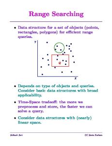
SpoolSep Principles Main incentives
• Gravity-based Separation (field proven & robust process ) • Made of long parallel pipes with reduced thickness compared to large pressure vessels to cope with Deep & Ultra Deepwaters • Higher interfacial areas / lower rising distance for oil droplets (improved efficiency) • Good slug handling capabilities • Modular system : based on deepwater spools design • Flexible design to cope with wide range of inlet parameters
Design principles
• Ensure equal fluid distribution • Same Process control philosophy as per single vessel • Provide required residence time for efficient oil/water separation
Typical spool installation sequence
MCE Deepwater Development 2016
SpoolSep Principles Typical Performances Spool outlet : several options Independent outlet for each phase Oil and gas recombination (stand pipe) + water outlet
Separation in mainpipe Gas
Stand pipe for • Oil level regulation • Gas & Oil recombination
Oil
Design Process criteria: • Phase velocity • Residence time / Cut-off diameter Selection of: • Number of spools • Spool diameter • Spool length
Water
Downstream bulk separator • Maximum OiW: 1000-2000 ppm • Maximum WC in oil stream: 15% Re-injection requirements • OiW: 20-100 ppm • TSS: 1 to 10 ppm • Solid particle size: 1-50µm
Water
Feedline
Base case stand pipe
Gas+ Oil
All individual outlets are commingled into a single outlet by phase Flow Splitter
Multiphase production from wells
Heavy Collector
Water Injection Pumps (O/W interface control)
Light Collector
Inlets & Outlets in the same area
Oil and Gas exported to surface (MPP) or separately
MCE Deepwater Development 2016
Subsea Station Design Subsea Station Architecture • 1 or 2 foundations • •
1 for the station with all the process 1 smaller for pipes support (if needed)
• 1 subsea station with connecting all the equipments • •
All active parts gathered on same structure Standard integration and test principle
Separation spools modules
• Within typical spool size envelop • Optimization of layout with compact connection • Retrievable by IMR vessels
Artistic view of SpoolSep Separation Station
MCE Deepwater Development 2016
Separation Spool Module Separator Outlet Height 4 to 6 m
Spool Outlet Feed Line OD 8” typ.
Separator Inlet
Spool Overview
1 off 3-bores clamp connector Or 1 off dual-bore clamp connector + 1 off single bore clamp connector
Pipe separator OD 18” to 50” typical
Spool Inlet
Aker Solutions
MCE Deepwater Development 2016
Installation and Maintenance
Typical subsea module handling Optimized connection for easier ROV operation Standard installation sequence Easy Spool recovery
MCE Deepwater Development 2016
Qualification Tests
Testing Flow loop
Phase 1: Design Feasibility
• Fluid distribution & level symmetry • Gravity separation efficiency o o o
Tests loop built with 4 spools at reduced scale (200mm ID, 18m long) Model oils/Tap Water/Air Flows at ambient conditions for visualization Variation of operating conditions: flowrates / WC/ GVF/ shear level
Symetrical behaviour whatever the flow regimes Assessment of flow regimes impact on performances and level control requirements Definition of velocity criteria to ensure separated phases with required quality
• Equal fluid distribution and balanced phase composition inside each spool • Symmetrical behavior of spools: validation of the base principle for level control philosophy • High level stabilty at separation conditions
• Assessment of design criteria for the range of 100 to 2000 ppmv Oil in Water contents
1.2 1.0 0.8 0.6 0.4 0.0
6 6
Dv90 125µm
1.4
00
4 4
Dv90 63µm
1.6
0.2 2 2
dv90/dstokes
1.8
500 500 0 0
dv50/dstokes
0.0
2.0
4.0
6.0
8.0
Water real velocity
10.0
12.0
Tests have confirmed separator operability giving design criteria to achieve required performance
MCE Deepwater Development 2016
Qualification Tests
Tests conditions:
Sand transport depends on: o
Liquid velocity and viscosity (Re)
Critical velocity, Vc Vc increases with increased viscosity
o
Sand granulometry
Pre-installation of a sand bed in a 110 mmID pipe 2 particle sizes: d50 64µm & 248µm - 2650 kg/m3 Oil or water wetted sand 2 sand bed heights (10%-30% HU) Flowing with different fluids Fluid velocity
Vc increases with increased particle size
o
Carrier fluid flow pattern
At low velocity, no impact of gas (if stratified flow) At high velocity, easier transport under slugging flows
Suspensions
Moving Bed
Stationary flow
o
Pipe slope has a significant impact on sand transport
No motion
Sand handling optimization (no need for internals)
Solid-Liquid Flow patterns
MCE Deepwater Development 2016
CONCLUSION As part of Subsea Processing systems, the SpoolSep brings robust solution to PWRI applications in deepwater
SpoolSep Subsea Station
Each separation spool can be installed and retrieved easily by subsea connectors Confirmation of stability and symmetry of flows within separation spools Reliable design to achieve required performances for water re-injection Better understanding of criteria for efficient sand transport by fluid flowing SpoolSep design flexibility (spool number, diameter and length) allows to accommodate wide range of requirements and conditions On-going JIP with TOTAL & PETROBRAS