Study of normal incidence three component multilayer mirrors in the range 20 nm - 40 nm Julien Gautier, Franck Delmotte, Marc Roulliay, Fran¸coise Bridou, Marie-Fran¸coise Ravet-Krill, Arnaud J´erˆome
To cite this version: Julien Gautier, Franck Delmotte, Marc Roulliay, Fran¸coise Bridou, Marie-Fran¸coise Ravet-Krill, et al.. Study of normal incidence three component multilayer mirrors in the range 20 nm - 40 nm. Applied optics, Optical Society of America, 2005, 44 (3), pp.384-390.
HAL Id: hal-00575801 https://hal-iogs.archives-ouvertes.fr/hal-00575801 Submitted on 27 Feb 2012
HAL is a multi-disciplinary open access archive for the deposit and dissemination of scientific research documents, whether they are published or not. The documents may come from teaching and research institutions in France or abroad, or from public or private research centers.
L’archive ouverte pluridisciplinaire HAL, est destin´ee au d´epˆot et `a la diffusion de documents scientifiques de niveau recherche, publi´es ou non, ´emanant des ´etablissements d’enseignement et de recherche fran¸cais ou ´etrangers, des laboratoires publics ou priv´es.
Study of normal incidence of three-component multilayer mirrors in the range 20ⴚ40 nm Julien Gautier, Franck Delmotte, Marc Roulliay, Françoise Bridou, Marie-Françoise Ravet, and Arnaud Jérome
We study theoretically and experimentally the increase of normal incidence reflectivity generated by addition of a third material in the period of a standard periodic multilayer, for wavelengths in the range 20 to 40 nm. The nature and thickness of the three materials has been optimized to provide the best enhancement of reflectivity. Theoretical reflectivity of an optimized B4C兾Mo兾Si multilayer reaches 42% at 32 nm. B4C兾Mo兾Si multilayers have been deposited with a magnetron sputtering system and a reflectivity of 34% at 32 nm has been measured on a synchrotron radiation source. © 2005 Optical Society of America OCIS codes: 340.7470, 310.1860.
1. Introduction
Classical extreme UV (EUV) multilayer mirrors consist of periodic stacks of two materials with a period thickness p deposited on a substrate. Owing to material absorption, the reflectivity of a periodic multilayer can be optimized by one’s changing the respective thicknesses of the two materials within the period. In the optimized multilayer1 the most absorbing material is thinner than p兾2. In fact, by reduction of the thickness of the most absorbing material 共tabs兲, the absorption of one period is reduced, and the light penetrates deeper into the multilayer. But reducing tabs also reduces the efficiency of each period (because it is no longer a quarter-wave stack). Thus there is a competition between the efficiency of each period and the number of efficient periods (which is limited by absorption). Different theoretical methods have been studied in order to improve multilayer reflectivity. Carniglia and Apfel in 1980 proposed a quasi-periodic structure in which p is kept constant but tabs is varied through-
The authors are with Laboratoire Charles Fabry de l’Institut d’Optique, Centre National de la Recherche Scientifique, Unité Mixte de Recherche 8501, Bât. 503, Centre Scientifique d’Orsay, 91403 Orsay Cedex, France. The e-mail address of F. Delmotte is
[email protected]. Received 22 December 2003; revised manuscript received 7 July 2004; accepted 12 October 2004. 0003-6935/05/030384-07$15.00/0 © 2005 Optical Society of America 384
APPLIED OPTICS 兾 Vol. 44, No. 3 兾 20 January 2005
out the multilayer.2 Basically, near the surface, tabs is low to minimize absorption, and, near the substrate, tabs is high (approximately p兾2) to improve the reflectivity.1 Following this idea, Singh and Braat proposed to incorporate additional materials of differing complex refractive indices in various regions of the stack.3 In fact, they added a third (and a fourth) material and made thicknesses of the three (or four) materials that were varied from one period to the next one: Less absorbing materials are mostly present near the surface, whereas most absorbing ones are located near the substrate. At a wavelength ⫽ 13.4 nm, the theoretical reflectivity of this new design reaches 78.1% as compared with 75.7% for a standard multilayer. The theoretical reflectance increase at this wavelength is only 3% in relative value. With respect to the higher wavelength range 共 ⬎ 50 nm兲, Larruquert has developed a theory on quasi-periodic multicomponent multilayers made of highly absorbing materials4,5 and established a rule of selection for the material to be used within a period in order to optimize the reflectivity. Unfortunately, this theory is no longer valid in the EUV range 共 ⬍ 50 nm兲 because most materials are only moderately absorbing. Nevertheless, Larruquert has proposed some examples of multicomponent multilayers in the EUV (at 30.4 and 50 nm) by using the same rule of selection. In theory, these structures provide high reflectivity increases, and the main increase happens when a third material is added to a classical multilayer.6
However, from a experimental point of view, to the authors’ knowledge, quasi-periodic multicomponent multilayers have never been produced in the EUV range 共 ⬍ 50 nm兲. In fact, there are two major difficulties for producing such multilayers. The first one is the need to calibrate each material thickness, taking into account interfacial interdiffusion or intermixing that often occur during multilayer deposition. The second one is the lack of useful characterization means for such structures. So, making quasi-periodic multilayers seems not to be an efficient way to increase significantly the reflectivity as compared with the difficulties one has to overcome to produce such structures. In the wavelength range 1.3 to 6.8 nm, Boher et al.7 have studied theoretically and experimentally periodic structures with three or four materials. They demonstrated that, even with periodical structures, the addition of a third material can improve the reflectivity, and they proposed a material selection criteria. Normal incidence mirrors for wavelengths ranging from 20 to 40 nm are of particular interest in the field of solar physics (EUV imaging telescopes) and new extreme ultraviolet (EUV) source developments (High Harmonic Generation sources, x-ray lasers, etc.). In this paper we focus on periodic multilayer structures, and we study theoretically and experimentally the increase of reflectance generated by the addition of a third material in the period for wavelengths in the range 20 to 40 nm. The first part deals with theoretical optimization of three-component periodical multilayers at ⫽ 32 nm. In the second part we explore the performances of these new multilayers 共B4C兾Mo兾Si兲 in the range 20⫺40 nm. In the last part we present the experimental results obtained with three-component multilayers at ⫽ 32 nm. 2. Three-Component Multilayer Design at ⴝ 32 nm
In standard multilayers (with two components), the choice of materials depends on two decisive factors: Materials must have the highest index contrast, but materials and interfaces must also be chemically stable. Different two-component multilayer mirrors have already been produced for wavelengths between 20 and 40 nm, in particular Mo兾Si,8 B4C兾Si,9,10 and Si3N4兾Si11 multilayers. These three kinds of multilayer present a good reflectivity, so a high contrast index is present between the two materials in this spectral region. Moreover, the aging and thermal stability of these structures have been reported to be satisfactory. For these reasons, we have selected Mo, Si, B4C, and Si3N4 materials as good candidates to produce three-component multilayers. In this part we theoretically study the possible reflectivity enhancement due to the addition of a third material in a standard multilayer. We have calculated the reflectivity of periodic multilayers with three materials per period at ⫽ 32 nm, and we have determined the material thicknesses that optimize the reflectivity. Each multilayer has 40 periods (more periods are useless owing to absorption). The reflec-
Table 1. Optical Constant at 32 nm and Density of B4C, Mo, Si, Si3N4a
Materials
n
k
Density 共g兾cm3兲
B4C a᎑Si Mo Si3N4
0.80527 0.92525 0.96369 0.81799
0.06334 0.00926 0.42567 0.10454
2.52 2.19 10.22 3.44
For Si we use density of amorphous silicium, 94% of the density of crystalline Si.
tivity is calculated at normal incidence with the iterative method.1 We make the hypothesis that the interfaces between adjacent layers are perfect; i.e., there are no scattering losses due to interface imperfections or compound formation. The optical constants of the four selected materials versus wavelength were calculated from the scattering factors of B, C, N,12 Mo,13 and Si14 and are listed in Table 1 for ⫽ 32 nm. In this table, n is the real part of the index, and k is the absorption coefficient. The densities are also listed. A density of 2.19 g兾cm3 is taken for amorphous silicium, which represents 94% of the density of crystalline silicium. The density of the three other materials are the tabulated density. For convenience, we have also plotted these optical constants in the complex plane on Figure 1. With these selected materials, we can make four triplets noted as 共B4C;Mo;Si兲, 共Si3N4;Mo;Si兲, 共B4C;Si3N4;Si兲, and 共B4C;Mo;Si3N4兲. For each triplet we have to optimize the order of the materials in the stack and the nature of the top layer: There are six structure possibilities per triplet. For example, with the triplet 共B4C;Mo;Si兲 we can realize six multilayers noted as B4C兾Mo兾Si, B4C兾Si兾Mo, Si兾B4C兾Mo, Si兾Mo兾B4C, Mo兾Si兾B4C, and Mo兾B4C兾Si. In the notation B4C兾Mo兾Si, the first material 共B4C兲 is on the top of the multilayer, and the last one 共Si兲 is on the substrate. All the 24 combinations (six per triplet) must be optimized if we want to find the best design
Fig. 1. Optical constants of B4C, Mo, a᎑Si, and Si3N4 at 32 nm plotted in the complex index plane. 20 January 2005 兾 Vol. 44, No. 3 兾 APPLIED OPTICS
385
Table 2. Reflectivity (R) at 32 nm and Layer Thicknesses of Three-Component Multilayers Made of B4C, Mo, and Si
Optimal Order
Structure
Thicknesses (nm)
Nonoptimal Order R (%)
Structure
Thicknesses R (nm) (%)
B4C兾Mo兾Si 4.1兾2.2兾11.3 42.0 B4C兾Si兾Mo 6.1兾11.6兾0 34.1 Mo兾Si兾B4C 2.4兾11.6兾3.6 37.0 Mo兾B4C兾Si 3.2兾0兾14.2 30.5 Si兾B4C兾Mo 11.5兾3.8兾2.3 34.3 Si兾Mo兾B4C 11.7兾0兾5.9 26.7 For each structure, the layer thicknesses have been calculated to optimize the reflectivity.
because the multilayer reflectivity depends not only on the choice of the three materials but also on their order in the stack and on the nature of the top layer. For each combination the program numerically optimizes the thickness of each material for a wavelength and a number of period. In Table 2 we present the results of reflectance optimization for the 共B4C;Mo;Si兲 triplet at ⫽ 32 nm. The six multilayers are classified into two columns. In the first one the addition of a third material increases the reflectivity: It is the optimal order column. In the second one the addition does not increase the reflectivity, and the optimization gives 0 ᎑nm thickness for one material: In this nonoptimal order column, we find standard multilayers. Each line represents a different top layer: The B4C top layer gives the best reflectivity, then Mo and Si. We can see that, for each top layer, a great increase of reflectivity is observed when the addition of a third material is in the good order. Concerning twocomponent multilayers, the best reflectivity is obtained for B4C兾Si and reaches 34.1%. The addition of Mo between B4C and Si (Mo deposited on Si) allows an increase in reflectivity up to 42%, whereas the addition of Mo between Si and B4C (Mo deposited on Si) gives no improvements. Thus the order of the stack in a three-component multilayer is crucial, as illustrated in Fig. 2. In this figure we compare the spectral response of three multilayers, calculated with IMD software.15 The continuous curve is the simulation of a standard B4C兾Si multilayer optimized for ⫽ 32 nm (thicknesses are given in Table 2). The dashed curve is a simulation of the B4C兾Mo兾Si multilayer previously optimized for ⫽ 32 nm (thicknesses are given in Table 2). The dotted curve represents the reflectivity of the same three-component multilayer with the same thicknesses but in reverse order: Si兾Mo兾B4C. A relative increase of 23% can be observed in the optimal order 共B4C兾Mo兾Si兲 and a fall of 63% can be observed when we inverse the order of the stack 共Si兾Mo兾B4C兲. Shown in Table 3 are the best results for the four triplets and the relative reflectivity increases obtained with three components instead of two. The first line is the same as the first line of Table 2. In the second column of Table 3, we present the best results of the standard multilayers. For all the triplets, the addition of a third material increases the reflectivity. 386
APPLIED OPTICS 兾 Vol. 44, No. 3 兾 20 January 2005
Fig. 2. Calculated reflectivity spectra of an optimized B4C兾Si multilayer (continus curve), an optimized B4C兾Mo兾Si multilayer (dashed curve), and a multilayer made of the same stack in reverse order 共Si兾Mo兾B4C兲 (dotted curve) at the incidence angle of 0°.
This enhancement is in relation with the index contrast between the third material and the materials of the standard multilayer (see Fig. 1). Indeed, for standard B4C兾Si multilayers the addition of Mo with a high contrast index increases the reflectivity to 23% (in relative values), whereas for Si3N4 (with a low index contrast) the increase is only 2.3%. For standard Mo兾Si multilayers the addition of B4C increases the reflectivity to 37.6% while the addition of Si3N4, which presents a lower contrast index, a relative increase of only 18% is observed. We note that, for the first three examples shown in Table 3, the order of the stack satisfies both Larruquert’s rule6 (material index has to run clockwise in the complex plane represented on Fig. 1) and Boher’s criterium7 (the more absorbing material must be deposited on the less absorbing material). Nevertheless, for the last triplet 共B4C;Mo;Si3N4兲 the optimal structure B4C兾Mo兾Si3N4 does not satisfy these selection rules. This shows that these two rules are not valid in the general case for wavelengths between 20 and 40 nm. This is, in fact, not really surprising. On the one hand, Boher’s criterium is derived from a particular simulation study and is not supported by any theoretical calculation. On the other hand, the demonstration of Larruquert’s rule is not valid for wavelengths below 50 nm.6 However, concerning the selection of materials, Larruquert’s selection rules and Boher’s selection criteria can be used as a guide to find the optimal structure. In conclusion, we observe by way of simulations that, in all cases, the addition of a third material can increase the reflectivity when the order of the stack is optimized. Concerning the selection of materials, it seems to be clear that, on a theoretical point of view, one has to choose materials with the highest optical index contrast for each material pair. Indeed, that is in agreement with Larruquert’s selection rules and with Boher’s selection criteria. As mentioned previ-
Table 3. Reflectivity (R) and Optimized Thicknesses for Three-Component Multilayers and Standard Multilayers
Three-Component Multilayers
Standard Multilayers
Structure
Thicknesses (nm)
R (%)
Relative Increase (%)
Structure
Thicknesses (nm)
R (%)
B4C兾Mo兾Si Si3N4兾Mo兾Si B4C兾Si3N4兾Si B4C兾Mo兾Si3N4
4.1兾2.2兾11.3 2.7兾2.5兾12.3 4.4兾1.8兾11.5 5.9兾6.2兾6.6
42.0 36.2 34.9 16.1
23.0 18.4 2.3 28.8
B4C兾Si Mo兾Si B4C兾Si B4C兾Mo
6.1兾11.6 3.2兾14.2 6.1兾11.6 7.0兾8.9
34.1 30.5 34.1 12.5
Best results for each triplet are reported.
ously, from an experimental point of view, one also has to take into account the stability of materials and interfaces, and this point provides an additional restriction to the theoretical possibilities. Concerning the order of the material in the stack, Larruquert’s rule or Boher’s criterium failed to predict the optimal order in the general case, for wavelengths ranging from 20 to 40 nm. Owing to this lack of reliable rules for defining the optimal order, all possible combinations have to be explored in simulation to find the best design (i.e., optimal order and thicknesses of materials in the stack). 3. Three-Component B4C兾Mo兾Si Multilayer in the Range 20ⴚ40
In Section 2 we have show that B4C兾Mo兾Si threecomponent multilayers present the highest reflectivity at ⫽ 32 nm. In this part we study the theoretical performances of such a structure versus wavelength and versus the number of periods in the stack. Figure 3 shows the calculated reflectance versus wavelength for the Mo兾Si, B4C兾Si, and B4C兾Mo兾Si multilayers. For each wavelength, the design has been optimized with our program. For all kinds of multilayer, the reflectance decreases (as expected) when the wavelength increases far from the Si7 absorption edge at 12.4 nm. At 13 nm, when optimizing the three-component B4C兾Mo兾Si multilayer, we find
Fig. 3. Peak reflectance versus wavelength for Mo兾Si (circles), B4C兾Si (triangles), and B4C兾Mo兾Si (squares) optimized multilayers. For each wavelength, the design has been optimized with our program.
a standard Mo兾Si multilayer (i.e., B4C thickness ⫽ 0). For all other wavelengths in the range 20 to 40 nm, we find an increase of reflectivity by using the three-component multilayer instead of standard Mo兾Si or B4C兾Si multilayers. The optimization of the reflectivity at ⫽ 32 nm versus the number of periods is shown in Fig. 4 for the B4C兾Mo兾Si three-component multilayer and the standard multilayer B4C兾Si. For each number of periods, we optimized material thicknesses in order to have the optimal reflectance at ⫽ 32 nm. In this graph we note that the number of periods (N) necessary to have 99% of the asymptotic reflectivity is lower for a three-component multilayer 共N ⫽ 14兲 than for a standard multilayer 共N ⫽ 22兲. This means that the number of layers (directly related to the number of interfaces) required to obtain 99% of the asymptotic reflectivity is approximately the same in both cases: 42 layers for the three-component multilayer and 44 for the standard multilayer. Nevertheless, the total thickness is lower for the threecomponent multilayer, so total absorption may be lower too, and reflectivity may be increased. Indeed, the great advantage of three-component multilayers
Fig. 4. (a) Optimized reflectance of B4C兾Mo兾Si multilayer (squares) and B4C兾Si multilayer (triangles) versus number of periods in the stack. (b) Optimized thicknesses of Mo (crosses), B4C (circles), and Si (rhombuses) corresponding to B4C兾Mo兾Si reflectance shown in (a) versus number of periods. 20 January 2005 兾 Vol. 44, No. 3 兾 APPLIED OPTICS
387
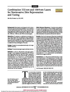
Fig. 5. Schematic of the magnetron sputtering deposition chamber: (a) top view and (b) side view.
is that this structure allows one to introduce more interfaces on a smaller thickness, which provides more contributions to the reflectance for the same absorption rate. 4. Three-Component B4C兾Mo兾Si Multilayer Fabrication and Characterization
Multilayers are deposited by use of a magnetron sputtering system equipped with four cathodes. The 80 mm ⫻ 200 mm rectangular targets are mounted in the bottom of the chamber with chimneys that limit the deposition region to the area directly above them. A background pressure of 2.7 ⫻ 10⫺6 Pa is obtained with a cryogenic pump. One deposits successive layers scanning the substrate above the target at a distance of 10 cm (Fig. 5). The thickness of each layer is controlled by the rotation velocity of the substrate on the target box (the motions are similar to those described by Montcalm et al.).16 The typical velocity is adjusted from 0.2°兾s to 2°兾s. The substrate is rotating around its axis of symmetry at 50 rpm in order to obtain a good azimuthal uniformity. During the process, we use a 0.27᎑Pa argon pressure in the deposition chamber. The plasma discharges are established with a rf power of 150 W for B4C and Si targets and a dc of 0.19 A for the Mo target. The effective deposition rates for the different materials are indicated in Table 4. Multilayers are deposited onto 2-in. 共1 in. ⫽ 2.54 cm兲 Si polished wafers. After deposition, the multilayer structure is controlled by means of the grazing-incidence x-ray reflectometry at 0.154 nm.17 By fitting the experimental
Fig. 6. Grazing-angle reflectometry at 0.154 nm of a B4C兾Mo兾Si5 multilayer: experimental data (dots) and fitted curve (solid curve).
data we can deduce the period of the multilayer, the thicknesses of the different layers, the average interfacial roughnesses, and the material complex index at 0.154 nm. Several multilayers have been deposited and controlled, and one representative example is shown in Fig. 6 with a fitted curve. The different parameters of the fitted curve are shown in Table 5. Notice that all the Bragg peaks up to the 11th order are well defined on the experimental data: This shows that the multilayer periodicity is good. Moreover, all estimated interfacial rouhnesses reported in Table 5 are very low (less than 0.6 nm). On this example we fit a period of 17.6 nm with the following composition: dB4C ⫽ 4.2 nm, dMo ⫽ 2.2 nm, and dSi ⫽ 11.2 nm (dx represents the thickness of the material x). One can see that the index contrast between B4C and Si is low at this wavelength, and this may induce a relative indetermination on the respective thicknesses of these two layers. However, simulations show that the reflectivity of three-component multilayers decreases only slightly when thicknesses are varied from the optimal calculated thickness. Reflectance in the EUV range has been measured on the ELETTRA synchrotron radiation source. Measurements have been carried out on the Bending Magnet for Emission Absorption and Reflectivity (BEAR) beamline18 with an incidence angle of 10 deg
Table 5. B4C兾Mo兾Si Multilayer Parameters Deduced from x-Ray Grazing-Angle Reflectometry Measurement
Layer Table 4. Effective Deposition Rates of Si, B4C, and Mo Layers
Materials Si Mo B4 C
388
rf Power (W) 150 0.11
dc Current (A)
Deposition Rate 共nm兾s兲
150 0.014
0.19 0.13
APPLIED OPTICS 兾 Vol. 44, No. 3 兾 20 January 2005
Si Substrate 1⫺Si 2⫺Mo 3⫺B4C ... 60⫺B4C a
Thickness (nm)
Roughness 1-n (nm) 共⫻10⫺6兲
Absorption k 共⫻10⫺6兲
⬁ 11.2 2.67 4.49
0.38 0.52 0.41 0.58
7.7 7.28 25.95 6.7
0.13 0.13 1.68 0.15
4.49
0.58
6.7
0.15
These parameters correspond to the fit curve of Fig. 6.
Fig. 7. Measured and calculated reflectivities of a B4C兾Mo兾Si three-component multilayer at 10 deg in S polarization. Parameters of the simulated curve are given in the text.
(near normal incidence) in S polarization. We used a normal incidence monochromator with an energy resolution, E兾⌬E, above 2000 and a silicon photodiode detector. The experimental reflectance versus wavelength of a B4C兾Mo兾Si multilayer is shown in Fig. 7. The period of this multilayer, deduced from grazingincidence x-ray reflectometry measurements, is 18.1 nm. We have measured a reflectance of 34%. This represents a relative increase of 29% as compared with the best reflectance obtained in this wavelength range (26.5% for Si兾B4C).9 We have also plotted on Fig. 7 the curve calculated with thicknesses and roughnesses deduced from grazing-incidence x-ray reflectometry measurements. The experimental spectrum and the calculated one are in quite good agreement. However, differences in reflectance and bandpass can be seen, and the reasons for this discrepancy are still under investigation. Concerning long-term stability, we have measured on an ELETTRA synchrotron radiation source a B4C兾Mo兾Si multilayer after eight months’ storage in air: The peak reflectance is 34%, and the peak position has not shifted with time. 5. Conclusion
The optimization design, fabrication, and characterization of three-component periodic multilayers have been described. Simulations show that the use of a third material allows an important increase of the reflectance if the order of the three materials in the stack is optimized. Owing to their high reflectance and chemical stability in standard multilayers, we have selected in a theoretical study Mo, Si, B4C, and Si3N4 materials as good candidates to produce three-component multilayers in the wavelength range 20 to 40 nm. The nature and thickness of the three materials have been optimized to provide the best enhancement of the calculated reflectivity. At ⫽ 32 nm, further enhancement is obtained by
the optimization of a B4C兾Mo兾Si multilayer (with B4C is on the top and Si on the substrate). We obtain a calculated reflectivity of 42%, whereas the theoretical reflectivity of B4C兾Si (which is the best design with two materials for this wavelength) is only 34%. Simulations show that B4C兾Mo兾Si multilayers are also promising for other wavelengths in the range 20 to 40 nm. B4C兾Mo兾Si multilayers with an optimized number of periods have been deposited with a magnetron sputtering system and characterized by x-ray grazing reflectometry and synchrotron radiation measurements. We obtained a experimental reflectivity of 34% at ⫽ 32 nm, which represents a relative increase of 29% as compared with the best standard multilayer reflectivity reported in the literature. The authors thank Bruno Pardo for fruitful discussions and Stefano Nannarone, A. Giglia, and the complete BEAR team at ELETTRA for their assistance during synchrotron radiation measurements. All multilayer depositions have been carried on the deposition machine of the Centrale d’Élaboration et de Métrologie des Optiques X implemented by Pôle d’Optique des Rayons X d’Orsay. Financial support for this research was partially provided by the Centre National de la Recherche Scientifique program Nouveaux Materiaux-Fonctionnalités Nouvelles. References 1. E. Spiller, Soft X-Ray Optics (SPIE, Bellingham, Wash., 1994). 2. C. K. Carniglia and J. H. Apfel, “Maximum reflectance of multilayer dielectric mirrors in the presence of slight absorption,” J. Opt. Soc. Am. 70, 523–534 (1980). 3. M. Singh and J. J. M. Braat, “Design of multilayer extremeultraviolet mirrors for enhanced reflectivity,” Appl. Opt. 39, 2189 –2197 (2000). 4. J. I. Larruquert, “Reflectance enhancement with subquarterwave multilayers of highly absorbing materials,” Opt. Soc. Am. A 18, 1406 –1414 (2001). 5. J. I. Larruquert, “New layer-by-layer multilayer design method,” Opt. Soc. Am. A 19, 385–390 (2002). 6. J. I. Larruquert, “Reflectance enhancement in the extreme ultraviolet and soft x rays by means of multilayers with more than two materials,” Opt. Soc. Am. A 19, 391–397 (2002). 7. P. Boher, L. Hennet, and Ph. Houdy, “Three materials soft x-ray mirrors: theory and application,” in Advanced X-Ray/EUV Radiation Sources and Applications, J. P. Knaueur and G. K. Shenoy, eds., Proc. SPIE 1345, 198 –212 (1990). 8. M. F. Ravet, F. Bridou, X. Zhang-Song, A. Jerome, F. Delmotte, R. Mercier, M. Bougnet, P. Bouyries, and J. P. Delaboudiniere, “Ion beam deposited Mo兾Si multilayers for EUV imaging applications in astrophysics,” in Advances in Optical Thin Films, C. Amra, N. Kaiser, and H. Macleod, eds., Proc. SPIE 5250, 99 –108 (2004). 9. D. L. Windt, S. Donguy, J. Seely, B. Kjornrattanawanich, E. Mgullikson, C. C. Wlton, L. Golub and E. DeLuca, “EUV multilayers for solar physics,” in Optics for EUV, X-Ray, and Gamma-Ray Astronomy, O. Citterio and S. L. O’Dell, eds., Proc. SPIE 5168, 1–11 (2004). 10. F. Delmotte, M. F. Ravet, F. Bridou, X. Song, A. Jerome, S. Boujdayane, S. Hubert, P. Zeitoun, M. Idir, and P. Troussel, “Depot et calibration de multicouches pour l’optique XUV dans la gamme 10⫺30 nm,” J. Phys. IV France 108, 255–258 (2003). 20 January 2005 兾 Vol. 44, No. 3 兾 APPLIED OPTICS
389
11. P. Boher, Ph. Houdy, L. Hennet, P. Müller, Z. G. Li, and D. J. Smith, “Silicon兾silicon oxide and silicon兾silicon nitride multilayers for extreme ultraviolet optical applications,” Opt. Eng. 30, 1049 –1060 (1991). 12. B. L. Henke, E. M. Gullikson, and J. C. Davis, “X-ray interactions: photoabsorption, scattering, and reflection at E ⫽ 50 – 30000 eV, Z ⫽ 1–92,” At. Data Nucl. Data Tables 54, 181–342 (1993). 13. R. Soufli and E. M. Gullikson, “Absolute photoabsorption measurements of molybdenum in the range 60 to 930 eV for optical constant determination,” Appl. Opt. 37, 1713–1719 (1998). 14. R. Soufli and E. M. Gullikson, “Reflectance measurement on clean surfaces for the determination of optical constants of materials in the EUV兾soft x ray region,” Appl. Opt. 36, 5499 – 5507 (1997).
390
APPLIED OPTICS 兾 Vol. 44, No. 3 兾 20 January 2005
15. IMD software developed by David Windt, see http://cletus. phys.columbia.edu兾⬃win. 16. C. Montcalm, S. Bajt, P. B. Mirkarimi, E. Spiller, F. J. Weber, and J. A. Folta, “Multilayer reflective coatings for extremeultraviolet lithography,” in Emerging Lithographic Technologies II, Y. Vladimirsky, ed., Proc. SPIE 3331, 42–50 (1998). 17. F. Bridou and B. Pardo, “Automatic characterization of layers stacks from reflectivity measurments. Application to the study of the validity conditions of the grazing X-rays reflectometry,” J. Optics (Paris) 21, 183–191 (1990). 18. F. Borgatti, A. De Luisa, B. Doyle, A. Giglia, N. Mahne, I. Pasquali, M. Pedio, G. Selvaggi, S. Nannarone, G. Naletto, M. G. Pelizzo, and G. Tondello, “The new Bear beamline: a short presentation,” elettra news 47(2003), see http://www. elettra.trieste.it/science/elettranews/volume47/en117.html.