STUDY FOR DESIGN AND IDENTIFICATION OF A BOLTED JOINT MODEL Mathieu Cloirec, Pierre-Alain Boucard, Laurent Champaney, St´ephane Guinard, Jyant Sen Gupta
To cite this version: Mathieu Cloirec, Pierre-Alain Boucard, Laurent Champaney, St´ephane Guinard, Jyant Sen Gupta. STUDY FOR DESIGN AND IDENTIFICATION OF A BOLTED JOINT MODEL. IX International Conference on Computational Plasticity, 2007, barcelona, Spain. Complas IX, 2 :889-892, 2007.
HAL Id: hal-01389752 https://hal.archives-ouvertes.fr/hal-01389752 Submitted on 5 Nov 2016
HAL is a multi-disciplinary open access archive for the deposit and dissemination of scientific research documents, whether they are published or not. The documents may come from teaching and research institutions in France or abroad, or from public or private research centers.
L’archive ouverte pluridisciplinaire HAL, est destin´ee au d´epˆot et `a la diffusion de documents scientifiques de niveau recherche, publi´es ou non, ´emanant des ´etablissements d’enseignement et de recherche fran¸cais ou ´etrangers, des laboratoires publics ou priv´es.
IX International Conference on Computational Plasticity COMPLAS IX E. O˜ nate and D.R.J. Owen (Eds) c
CIMNE, Barcelona, 2007
STUDY FOR DESIGN AND IDENTIFICATION OF A BOLTED JOINT MODEL M. Cloirec∗ , P.A. Boucard∗ , L. Champaney∗ , S. Guinard+ , J. Sen Gupta+ ∗Laboratoire de M´ecanique et Technologie (ENS Cachan/CNRS /Universit´e Paris 6) 61 Avenue Pr´esident Wilson, 94235 CACHAN CEDEX (France) +
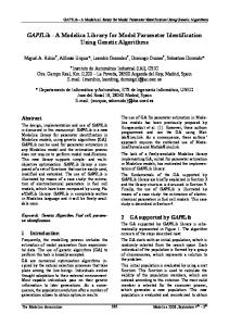
Centre de Recherche EADS 18, rue Marius Terce - BP 13050 - 31025 Toulouse Cedex 03 (France) Key words: bolted joint, macromodel, contact, friction Summary. The study deals with the behavior of bolted joints between the wings and the fuselage of an airplane. To study this complex structure, we use a classical finite element code with a simplified model (called macromodel) to avoid a large number of degrees of freedom implied by a fine discretization of the local geometry and non-linearities (contact, friction). During previous studies, the macromodel was constructed by simple springs. The use of this type of macromodel in assembly simulations enables to define the most loaded bolt. However, these simple springs do not allow to take into account non-linearities such as contact with friction. To face this problem, a new macromodel is considered.
1
Introduction
The aim of this work is to solve mechanical problems including frictional contact in bolted joint using a macromodel. This macromodel should be implemented in an usual finite element code and used for each bolted joint in the complete structure simulation. The 2-nodes macromodel element can be characterized via parameters (a gap, a tangential stiffness, an axial stiffness, a friction ratio, and a pretension for example). Once the nature of the macromodel is established, an identification of the parameters is proceed. To this purpose, simulations on a 3D structure defined as a mesomodel can be used. This structure is composed of two aluminium plates, one composite plate and a bolt. To carry out the simulations, we use a dedicated software [CHA 95] based on the LATIN method [LAD 99], which enables us to handle frictional contact between the different parts of the assembly (see figure 1). The mesomodel parameters seizure is lead through a specific multi-resolution process allowing an important wage of time [BOU 03]. In the next sections, two types of macromodel are developed: a contact macromodel and a frictional contact one. Finally, some results are presented.
1
M. Cloirec, P.A. Boucard, L. Champaney, S. Guinard, J. Sen Gupta
gap
sliding composite
deformed shape
pretension effect
bolt aluminum Figure 1: Bolted joint - mesomodel
2
Macromodel definitions
2.1
Macromodel for contact
k' - k
kt
j
(a) macromodel representation
e
k3
kt’-kt
(b) 1D-contact
k = k1 + k2 g k = k1
k2
j
k
macromodel element
k1
kn
(c) 3D-contact
c
k = k1 + k2 + k3
(d) 1D-frictional contact
Figure 2: Bolted joint - macromodel definitions
The contact macromodel in one dimension can be seen like a rheological model (represented by figure 2.b), and is composed of two different stiffnesses (k, k‘ ) and a gap (j). The contact macromodel behavior can be defined by: F = αe kδu + αc k‘ δu, where F is the force, δu the jump in displacement, k, k‘ the element stiffness before and after contact and αe , αc the ratio of the jump in displacement before and after contact. Considering this behavior, the ratio of the jump + in displacement after contact can be written as: αc = and its complementary term |δu| (before contact) as: αe = 1 − αc . Using a standard linear discretization, the specific element behavior becomes: ‘
{F } = αe [K]{U } + αc [K ]{U };
h
K
i
=
"
k −k −k k
#
and
h
K
′
i
=
"
′
k ′ −k
−k ′ k
′
#
(1)
To solve the non-linear problem of contact, a standard newton algorithm is used in a quasistatic study. Consequently, the residual {R} is computed such that: {R} = αe [K]{U + ∆U } + αc [K ‘ ]{U + ∆U } and the tangent matrix [K T ] is chosen such that [K T ] = [K] if αc = 0 or [K T ] = [K ‘ ] if αc > 0. In a three-dimensional configuration, a simplified beam model is used 2
M. Cloirec, P.A. Boucard, L. Champaney, S. Guinard, J. Sen Gupta
to connect two shells and consequently defines a patch representing a contact joint between two parts (cf. fig. 2.a). To link the shell elements, the simplified beam model contains three translation dof and three rotation dof for each node (similar to a shell junction element integrated into a standard finite element code such as those exposed in [VAD 06], [MAY 07]). Considering the contact from a translational point of view, relations between translations and rotations implied by the element stiffness matrix are decoupled. As a result, the macromodel element stiffness matrix (Kel ) is defined by: h
Kel
i
=
"
M −M
−M M
#(
Mij = 0 ∀i 6= j M11 = kn ; M22 = M33 = kt ; M44 = M55 = M66 = kr
(2)
where kn is the axial stiffness, kt the radial stiffness and kr the rotational stiffness. Furthermore, the terms of the joint element matrix coupling the rotations are chosen high to impose rigid body motion for rotation. To know when the contact occurs, a normed jump in displacement is computed in the local tangential plane of the specific element and compared with the gap. In ′ this contact model, the parameters are two radial stiffnesses (kt ,kt ), an axial stiffness (kn ) and a gap (j). Thus, considering the shell assembly, the joint is considered as a rigid body taken into account the translational contact. 2.2
Macromodel for frictional contact
For frictional contact (cf. fig. 2.d), three states are considered: sticking, sliding and contact. First, the plates are stuck. When a critical load (G) is attained, one plate slide over the second plate and finally the bolt contacts the plates. To model the friction, a coulomb law is used with a threshold force G = f (Pc , µ), where Pc is the pretension in the bolt and µ the friction ratio. The states can be expressed as: states sticking sliding contact
conditions Ft · sign(U˙ t ) < G |δut | − kGe < j and Ft · sign(U˙ t ) ≥ G |δut | − kGe ≥ j and Ft · sign(U˙ t ) ≥ G
displacement ratio αe = 1; αg = 0; αc = 0 G ; αg = 1 − αe ; αc = 0 αe = ke ·|δu t| αe = 1; αg = |δuj t | ; αc = 1 − (αe + αg )
Consequently, the residual is computed by the relation: {R} = αe [K e ]{U + ∆U } + αg [K g ]{U + ∆U } + αc [K c ]{U + ∆U }, and the tangent matrix ([K T ]) is chosen such that: [K T ] = [K e ] for sticking, [K T ] = [K g ] for sliding, [K T ] = [K c ] for contact, where Ft is the radial force, δut the radial jump in displacement, K e the element stiffness before contact, K g the regularization term during sliding, K c the element stiffness after contact, U˙ t the radial displacement speed, G the threshold friction force and αe , αg , αc the ratio of the jump in displacement related to the three states. 3
Numerical experiments
Three different cases are exposed in figures 3.a, 3.b, 3.c. The first problem is related to a structure of 2 plates under a traction-compression load with a macromodel simulating the contact (cf. fig. 3.a). The second problem is referred to a structure of 2 plates under compression linked 3
M. Cloirec, P.A. Boucard, L. Champaney, S. Guinard, J. Sen Gupta
by four bolted joints (cf. fig. 3.b). The last problem presents a one dimensional problem including frictional contact (cf. fig. 3.c). The variation of the jump in displacement in direction x is displayed versus the load in the same direction for the three cases. 200.00
Fx
Fx
Fx 150.00
100.00
50.00
δux
δux
δux
0.00 0.00
(a) 3D contact problem
(b) 3D contact problem - 4 joints
0.04
0.08
0.12
0.16
0.20
(c) 1D friction problem
Figure 3: Bolted joint - macromodel results
4
Conclusion
The key point of using the macromodel and the mesomodel presented is that they rest on a physical meaning. On one hand, the geometry and the initial conditions allow an identification of the macromodel’s gap and pretension. On the other hand, real or virtual (mesomodel simulations presented in figure 1) elementary tests could enable to identify the macromodel’s stiffnesses and friction ratio. Once the macromodel’s parameters will be defined, the final aim will be to carry out a simulation on a complex structure joining the wings to the fuselage composed of plates. REFERENCES [BOU 03] Boucard P.A. et Champaney L., A suitable computational strategy for the parametric analysis of problems with multiple contact, International Journal for Numerical Methods in Engineering, vol. 57, 2003, p. 1259-1281. [CHA 95] Blanz´ e C., Champaney L., Cognard J.Y. and Ladev` eze P., A modular approach to structure assembly computations. Application to contact problems, Engineering Computations, vol. 13, n 1, 1995, p. 15–32. `ze, P., Nonlinear Computational Structural Mechanics - New Approaches [LAD 99] Ladeve and Non-Incremental Methods of Calculation. Springer Verlag, (1999). [VAD 06] Vadean A., Leray D., Guillot J., Bolted joints for very large bearings - numerical model development, Finite Elements in Analysis and Design, vol. 42, 2006, p. 298-313. [MAY 07] Mayer M.H., Gaul L., Segment-to-segment contact elements for modelling joint interfaces in finite element analysis , Mechanical Systems and Signal Processing, vol. 21, 2007, p. 724-734.
4