STATE OF WISCONSIN Department of Safety and Professional Services --------------------------------------------------------------------------------------------------------------------IN THE MATTER OF RULEMAKING : NOTICE OF TIME PERIOD PROCEEDINGS BEFORE THE : FOR COMMENTS FOR THE DEPARTMENT OF SAFETY AND : ECONOMIC IMPACT ANALYSIS PROFESSIONAL SERVICES : --------------------------------------------------------------------------------------------------------------------NOTICE IS HEREBY GIVEN of the time period for public comment on the economic impact of this proposed rule of the Department of Safety and Professional Services relating to wall bracing for one- and two-family dwellings, including how this proposed rule may affect businesses, local government units and individuals. The comments will be considered when the Department prepares the Economic Impact Analysis pursuant to section 227.137 of the Wisconsin Statutes. Written comments may be submitted to: Sam Rockweiler, Rules Coordinator Division of Policy Development Department of Safety and Professional Services PO Box 8366 Madison, WI 53708-8366
[email protected] The deadline for submitting economic impact comments is February 6, 2014. PROPOSED ORDER An order of the Department of Safety and Professional Services to amend SPS 321.02 (1) (c), 321.23, Table 321.25–A, 321.25 (7) (d) and (8) (a) (Note), and 320 to 325 Appendix – Minimum Fastener Schedule Table; and to repeal and recreate SPS 321.25 (8) (b) to (h) and (9), relating to wall bracing for one- and two-family dwellings. --------------------------------------------------------------------------------------------------------------------ANALYSIS Statutes interpreted: Sections 101.63 (intro.) and (1) (intro.) and (5). Statutory authority: Sections 227.11 (2) (a) and 101.63 (intro.) and (1) (intro.).
Explanation of agency authority: Section 227.11 (2) (a) of the Statutes authorizes the Department to promulgate rules interpreting any statute that is enforced or administered by the Department, if the rule is considered necessary to effectuate the purpose of the statute. Sections 101.63 (intro.) and (1) (intro.) require the Department to adopt rules which establish standards for the construction and inspection of one- and two-family dwellings and components thereof. No set of rules may be adopted that has not taken into account the costs of specific code provisions to home buyers in relationship to the benefits derived from the provisions. Related statute or rule: Various other statutes and rules promulgated by the Department address construction and inspection of public buildings and places of employment, and some of those rules likewise address designing those structures to withstand wind loads. Plain language analysis: These rule revisions would clarify and simplify the prescriptive methods in chapter SPS 321 for designing wall bracing for one- and two-family homes, to adequately withstand wind loads. Summary of, and comparison with, existing or proposed federal regulation: An Internet-based search of the Code of Federal Regulations (CFR) and the Federal Register did not find any federal regulations relating to the rule revisions herein for one- and two-family dwellings – other than the preemptive construction, installation, and safety standards for manufactured homes in 24 CFR Parts 3280 and 3285. Comparison with rules in adjacent states: Illinois: An Internet-based search did not reveal the existence of a statewide one- and two-family dwelling code. Dwelling regulation appears to be left up to the individual local units of government. Iowa: An Internet-based search did not reveal the existence of a statewide one- and twofamily dwelling code. Dwelling regulation appears to be left up to the individual local units of government. Michigan: An Internet-based search revealed a mandatory, statewide one- and twofamily dwelling code. The Residential Construction Code under the Construction Code Commission’s General Rules, in section 408.305, contains the state amendments to the 2009 International Residential Code (IRC) developed by the International Code Council, and includes
2
wall-bracing requirements that are similar to the requirements which would be replaced by the rule revisions contained herein. Minnesota: An Internet-based search revealed a mandatory, statewide one- and twofamily dwelling code. The Minnesota Department of Labor and Industry, in Chapter 1309, adopts the 2006 IRC, chapters 2-10 and 43. Chapters 2-10 contain the general construction provisions of the IRC, which include wall-bracing requirements that are similar to the requirements which would be replaced by the rule revisions contained herein. Summary of factual data and analytical methodologies: The Department received input during several meetings with the Dwelling Code Council. The makeup of this Council is established under section 15.407 (10) of the Statutes and consists of members who are appointed by the Governor. The Council includes representatives of several types of small businesses. Through this Council, the Department was able to gather information on the potential impacts of the rule revisions contained herein. Analysis and supporting documents used to determine effect on small business or in preparation of economic impact analysis: The rule revisions are not expected to significantly impact small business because they would clarify and simplify current requirements rather than impose new restrictions. Fiscal Estimate and Economic Impact Analysis: The Department is currently soliciting information and advice from businesses, local government units, and individuals in order to prepare an Economic Impact Analysis. Effect on small business: These rule revisions are not expected to have an economic impact on small businesses, as defined in section 227.114 (1) of the Statutes. The Department’s Regulatory Review Coordinator may be contacted by e-mail at
[email protected], or by calling (608) 2668608. Agency contact person: Sam Rockweiler, Rules Coordinator, at the Department of Safety and Professional Services, Division of Policy Development, 1400 East Washington Avenue, Room 151, P.O. Box 8935, Madison, WI, 53708-8935; or at telephone (608) 266-0797; or e-mail at
[email protected]. Place where comments are to be submitted and deadline for submission: Comments may be submitted to Sam Rockweiler, Rules Coordinator, at the Department of Safety and Professional Services, Division of Policy Development, 1400 East Washington
3
Avenue, Room 151, P.O. Box 8366, Madison, WI, 53708-8366; or by e-mail to
[email protected]. Comments must be received on or before February 6, 2014, to be included in the record of rule-making proceedings. --------------------------------------------------------------------------------------------------------------------TEXT OF RULE SECTION 1.
SPS 321.02 (1) (c) is amended to read:
SPS 321.02 (1) (c) Wind loads. 1. Dwellings shall be designed and constructed to withstand a horizontal and uplift pressure of 20 pounds per square foot acting over the surface area, except wind loads may be determined in accordance with ASCE 7–05, Minimum Design Loads for Buildings and Other Structures. 2. No wind load reduction may be permitted for the shielding effect of other buildings. 3. Compliance with the prescriptive construction requirements of this chapter shall be deemed to be compliance with this paragraph.
SECTION 2.
SPS 321.23 is amended to read:
SPS 321.23 Wall design. (1) LIVE AND DEAD LOADS. All walls shall support all superimposed vertical dead loads and live loads from floors and roofs. (2) HORIZONTAL WIND LOAD. Walls shall be designed to withstand a horizontal wind pressure of at least 20 pounds per square foot applied to the vertical projection of that portion of the dwelling above grade. No wind load reduction shall be permitted for the shielding effect of other buildings. Walls shall comply with the design requirements of s. SPS 321.02. Compliance with the prescriptive construction requirements of s. SPS 321.25 shall be deemed to be compliance with this section.
SECTION 3.
SPS Table 321.25–A is amended to read: Table 321.25−A SIZE, HEIGHT AND SPACING OF WOOD STUDSa (Partial Table)
Stud Size (inches) Laterally Unsupported Stud Heighta (feet)
Bearing Walls Maximum Spacing When Supporting Maximum Spacing One Floor, Roof and When Supporting Roof and Ceiling Ceiling (inches) Only (inches)
4
Nonbearing Walls Maximum Spacing When Supporting Two Floors, Roof and Ceiling (inches)
Maximum Spacing When Supporting One Floor Only (inches)
Laterally Unsupported Stud Heighta (feet)
Maximum Spacing (inches)
10 12 1012
2x4 2x6
SECTION 4.
24 16 24
16 12 24
16
24 16 24
14
24
20
24
SPS 321.25 (7) (d) and (8) (a) (Note) are amended to read:
SPS 321.25 (7) (d) Cripple walls with a stud height of 14 inches or greater shall be braced in accordance with sub. (8) or (9). (8) (a) Note: Acceptable engineering wall bracing practices include any of the following: 1. The provisions under s. section R602.10 or R602.12 of the International Residential Code (IRC) – 2009 2012. 2. Design in accordance with the engineering basis of the 2012 IRC bracing provisions as described in Crandell, J. and Martin, Z., “The Story Behind the 2009 IRC Wall Bracing Provisions (Part 2: New Wind Bracing Requirements),” Wood Design Focus, Forest Products Society, Peachtree Corners, GA, Spring 2009. 3. Bracing manufacturer installation instructions and code-compliance data.
SECTION 5.
SPS 321.25 (8) (b) to (h) and (9) are repealed and recreated to read:
SPS 321.25 (8) (b) Bracing materials and methods. Wall bracing shall use the materials and methods listed in Table 321.25–G or approved alternatives capable of providing the required wind load resistance as determined in accordance with s. SPS 321.02 (1) (c). Alternative bracing methods that are an approved as equivalent to one of the bracing methods listed in Table 321.25– G shall be permitted to use the requirements for that bracing method contained herein. Table 321.25–G BRACING METHODSa Method
LIBc Let-in bracing
Minimum Brace Material Thickness or Size
1x4 wood brace (or approved metal brace installed per manufacturer instructions)
Minimum Maximum Braced Wall Nominal Panel Width or Wall Brace Angle Heightb Intermittent Bracing Methods
10’
45o angle and maximum 16” o.c. stud spacingb
DWB Diagonal wood boards
¾” (1” nominal) for maximum 24” o.c. stud spacing
10’
48”
WSP
3/8” for maximum
10’
48”
5
Connection Criteria Minimum Fasteners
Maximum Spacing
2-8d common nails or 3-8d box nails (21/2” long x 0.113” diameter)
Per stud and top and bottom platese
2-8d box nails (21/2” long x 0.113” diameter) or 2 – 13/4” long 16 gage staples 6d common nail or
Per stud and top and bottom platese 6” edges, 12”
Wood structural panel
16”o.c. stud spacing; 7/16” for maximum 24” o.c. stud spacing
SFB Structural fiberboard sheathing
½” for maximum 16” o.c. stud spacing
GB Gypsum board (installed on both sides of wall)
½” for maximum 24” o.c. stud spacing
PCP Portland cement plaster
¾” for maximum 16” o.c. stud spacing
d
CS-WSP Continuous sheathed WSP CS-SFBd Continuous sheathed SFB PF Portal frame
10’
48”
10’
8d box nail (2-1/2” long x 0.113” diameter) or 7/16” crown 16 gage staples, 1-1/4” long 1-1/2” long x 0.120” diameter galvanized roofing nails or 1” crown 16 gage staples, 1-1/4” long
96”
5d cooler nails, or #6 screws
1-1/2” long, 11 gage, 7/16” diameter 10’ 48” head nails or 7/8” long, 16 gage staples Continuous Sheathed Bracing Methods
3/8” for maximum 16”o.c. stud spacing; 7/16” for maximum 24” o.c. stud spacing ½” for maximum 16” o.c. stud spacing 7/16”
12’
field (nails) 3” edges, 6” field (staples)
3” edges, 6” field 7” edges, 7” field (including top and bottom plates) 6” o.c. on all framing members
Same as WSP
Same as WSP
Same as SFB
Same as SFB
Refer to Figure 321.25–A
Refer to Figure 321.25–A
Refer to Table 321.25-H
Narrow Panel Bracing Refer to Figure 12’ 321.25–A
a
The interior side of all exterior walls shall be sheathed minimum ½” gypsum wall board. All edges of panel-type wall bracing, except horizontal joints in GB bracing, shall be attached to framing or blocking. b The actual measured wall height shall include stud height and thickness of top and bottom plates. The actual wall height shall be permitted to exceed the listed nominal values by not more than 4 inches. Tabulated bracing amounts in s. SPS 321.25 (8) (c) are based on a 10-foot nominal wall height for all bracing methods and shall be permitted to be adjusted to other nominal wall heights not exceeding 12 feet in accordance with footnotes to Table 321.25–I or Table 321.25–J. c
Method LIB may not be permitted for walls supporting a roof and two floors. Two LIB braces installed at a 60o angle from horizontal shall be permitted to be substituted for each 45o angle LIB brace.
d
Bracing methods CS-WSP and CS-SFB shall have sheathing installed on all sheathable surfaces above, below, and between wall openings. e
Shall be attached to the top and bottom plates and any intermediate studs, in one continuous length.
Table 321.25–H MINIMUM WIDTHS OF METHOD CS-WSP AND CS-SFB BRACED WALL PANELS Maximum Opening Height Adjacent to Braced Wall Panel Up to 5’– 4” Up to 6’– 8” Up to 8’
Minimum Length of Braced Wall Panel (inches) 8’ Tall Wall 24 32 48
6
9’ Tall Wall 27 30 41
10’ Tall Wall 30 30 38
12’ Tall Wall 36 36 36
Up to 9’ Up to 10’ Up to 12’
-
54 -
46 60 -
41 48 72
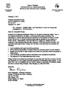
Figure 321.25–A METHOD PF – PORTAL FRAME BRACE CONSTRUCTION EXTENT OF HEADER WITH DOUBLE PORTAL FRAMES (TWO BRACED WALL PANELS) EXTENT OF HEADER WITH SINGLE PORTAL FRAME (ONE BRACED WALL PANEL) 2' -18' FINISHED WIDTH OF OPENING FOR SINGLE OR DOUBLE PORTAL TENSION STRAP (ON OPPOSITE SIDE OF SHEATHING)
4' MAX PONY WALL HEIGHT
BRACED WALL LINE WSP OR CS-WSP CONTINUOUSLY SHEATHED BRACE PANEL AL WITH WOOD STRUCTUR PANELS
FASTEN SHEATHING TO HEADER WITH 8D COMMON OR GALVANIZED BOX NAILS IN 3" GRID PATTERN AS SHOWN 10' MAX. PANEL HEIGHT
12' MAX TOTAL WALL HEIGHT
MIN. 3" X 11-1/4" NET HEADER STEEL HEADER PROHIBITED
FASTEN TOP PLATE TO HEADER WITH TWO ROWS OF 16D SINKER NAILS AT 3" O.C. TYP.
IF NEEDED PANEL SPLICE EDGES SHALL OCCUR AND BE ATTACHED TO COMMON BLOCKING WITHIN 24" OF WALL MID- HEIGHT. ONE ROW OF 3" O.C. NAILING IS REQUIRED IN EACH PANEL EDGE.
HEADER TO JACK-STUD STRAP ON BOTH SIDES OF OPENING OPPOSITE SIDE OF SHEATHING; STRAP CAPACITY SHALL EQUAL 1,000 LBS. OR 4,000 LBS. WHEN PONY WALL IS PRESENT MIN. DOUBLE STUD FRAMING COVERED WITH MIN. 7/16" THICK WOOD STRUCTURAL PANEL SHEATHING WITH 8D COMMON OR GALVANIZED BOX NAILS AT 3" O.C. IN ALL FRAMING (STUDS, BLOCKING, AND SILLS) TYP.
MIN. 7/16" WOOD STRUCTURAL PANEL SHEATHING
TYPICAL PORTAL FRAME CONSTRUCTION
MINIMUM PANEL LENGTH WALL HEIGHT, ft.
8
9
10
11
12
PANEL LENGTH, in.
16
18
20
22
24
MIN. 2X4 STUDS WITH PONY WALL HEIGHT UP TO 2'; MIN. 2X6 STUDS WITH PONY WALL HEIGHT GREATER THAN 2'.
MIN. DOUBLE POST COMMON STUD AND (KING AND JACK STUD). ONE OR OF MORE NUMBER JACK SHOULDER STUDS STUDS PER TABLES R502.5(1) & (2). PER s. SPS 321.25 (3) (b)
MIN. (2) 1/2" DIAMETER ANCHOR BOLTS
MIN. (2) ½” DIAM. ANCHOR BOLTS INSTALLED PER R403.1.6 WITH 3"x3"x3/16" PLATE INSTALLED WASHER PER s. SPS 321.18 (1) (c)
ANCHOR BOLTS PER ANCHOR BOLTS SECTION R403.1.6 PER SPS s. 321.18
(1) (c) OVER CONCRETE OR MASONRY BLOCK FOUNDATION
WOOD STRUCTURAL PANEL SHEATHING TO TOP OF BAND OR RIM JOIST
NAIL SOLE PLATE TO JOIST PER
NAIL SOLE PLATE TO TABLE R602.3(1) JOIST PER TABLE IN APPENDIX
MIN. OVERLAP 9-1/4"
OVER RAISED WOOD FLOOR - FRAMING ANCHOR OPTION
WOOD STRUCTURAL PANEL SHEATHING CONTINUOUS OVER BAND OR RIM JOIST
(2) FRAMING ANCHORS APPLIED ACROSS SHEATHING JOINT WITH A CAPACITY OF 670 LBS IN THE HORIZONTAL AND VERTICAL DIRECTIONS
NAIL SOLE PLATE TO JOIST NAIL SOLE PLATE TO PER TABLE JOIST PER TABLE IN R602.3(1)
WOOD STRUCTURAL PANEL SHEATHING OVER APPROVED BAND OR RIM JOIST
APPENDIX APPROVED BAND OR RIM JOIST
ATTACH SHEATHING TO BAND OR RIM JOIST WITH 8D COMMON NAILS AT 3" O.C. TOP AND BOTTOM
NAIL SOLE PLATE
NAIL TO TOSOLE JOIST PLATE PER TABLE JOIST PERR602.3(1) TABLE IN APPENDIX
NAIL SOLE PLATE TO JOIST NAIL SOLE PLATE PER TABLE TO JOIST PER R602.3(1)
WOOD STRUCTURAL PANEL SHEATHING OVER APPROVED BAND OR RIM JOIST
OVER RAISED WOOD FLOOR - OVERLAP OPTION
FRONT ELEVATION
TABLE IN APPENDIX APPROVED BAND OR RIM JOIST
SECTION
(c) Bracing amount. Bracing methods and materials complying with Table 321.25–G shall be applied to exterior walls in accordance with all of the following requirements: 1. For the purpose of determining bracing amounts, the outermost extents of the building plan at each floor level shall be circumscribed with a rectangle to define the overall length of each building side as shown in Figure 321.25–B. 2. In no case may the amount of bracing be less than two braced wall panels on exterior walls parallel to each rectangle side for each floor level of the building.
7
3. Where used, the number of intermittent brace panels applied to walls parallel to each rectangle side shall comply with Table 321.25–I. 4. Where used, the total length of continuous sheathed brace panels applied to walls parallel to each building side shall comply with Table 321.25–J. 5. The location of brace panels applied to walls parallel to each building side shall comply with Figure 321.25–C. 6. The interior side of exterior walls shall be sheathed with minimum ½” gypsum board interior finish unless otherwise permitted to be excluded by this subsection. 7. Balloon-frame walls shall have a maximum height of two floors unless constructed in accordance with an approved design. Wall framing shall be continuous from the lowest floor to the wall top plate at the roof. All edges of sheathing shall be supported on and fastened to blocking or framing. Braced wall panels may not be required on the balloon-frame wall portion provided the bracing amount and brace spacing requirement are satisfied for the building side. Where brace panels must be located on the balloon-frame wall portion to satisfy bracing requirements for the building side containing the balloon-frame wall portion, brace wall panels shall extend to the full height of the balloon-frame wall. Figure 321.25–B DEFINING BUILDING SIDES AND LENGTHS WITH A CIRCUMSCRIBED RECTANGLEa,b,c
=
OR
ONE RECTANGLE
TWO RECTANGLES
a
Each floor plan level shall be circumscribed with one or more rectangles around the entire floor plan at the floor level under consideration as shown. When multiple rectangles are used, each side shall be braced as though it were a separate building and the bracing amount added together along the common wall where adjacent rectangles overlap. b Rectangles shall surround all enclosed plan offsets and projections. Chimneys, partial height projections, and open structures, such as carports and decks, shall be excluded from the rectangle. c Each rectangle shall have a maximum rectangle length-to-width ratio of 3:1.
Table 321.25–I REQUIRED NUMBER OF INTERMITTENT BRACED WALL PANELS ON EXTERIOR WALLS PARALLEL TO EACH RECTANGLE SIDE AT EACH FLOOR LEVELa,b,c,d,e,f,g,h Required Number of Brace Panels on a Building Side Length of Perpendicular Side (feet) ≤25’ 50’ 75’
Wall Supporting:
8
Roof and ceiling only
1
2
3
One floor, roof and ceiling
2
4
6
Two floors, roof and ceiling
3
6
9
a
Interpolation shall be permitted. Extrapolation is prohibited. Table applies to wind exposure category B. For wind exposure category C or D, multiply number of braced wall panels required by 1.3 or 1.6, respectively. Wind exposure category B is comprised of urban and suburban areas, wooded areas, or other terrain with numerous closely spaced obstructions having the size of single-family dwellings or larger. Exposure B shall be assumed unless the site meets the definition of another type exposure. Wind exposure category C is comprised of flat, open country and grasslands with scattered obstructions, including surface undulations or other irregularities, having heights generally less than 30 feet extending more than 1,500 feet from the building site in any quadrant. This exposure also applies to any building located within Exposure B type terrain where the building is directly adjacent to open areas of Exposure C type terrain in any quadrant for a distance of more than 600 feet. Wind exposure category D is comprised of flat, unobstructed areas exposed to wind flowing over open water for a distance of at least 1 mile. This exposure applies only to those buildings and other structures exposed to the wind coming from over the water. Exposure D extends inland from the shoreline a distance of 1,500 feet or 10 times the height of the building or structure, whichever is greater. c Tabulated values are based on a nominal wall height of 10 feet. For nominal wall heights other than 10 feet and not more than 12 feet, multiply the required number of brace panels by the following factors: 0.9 for 8 feet, 0.95 for 9 feet, 1.15 for 11 feet, or 1.3 for 12 feet. d Tabulated values are based on a roof eave-to-ridge height of 10 feet. For roof eave-to-ridge heights other than 10 feet, multiply the required number of brace panels by the following factors for each floor level support condition: Roof only – 0.7 for 5 feet, 1.3 for 15 feet, or 1.6 for 20 feet Roof + 1 Floor – 0.85 for 5 feet, 1.15 for 15 feet, or 1.3 for 20 feet Roof + 2 Floors – 0.9 for 5 feet or 1.1 for 15 feet. e Where minimum ½” gypsum wall board is not included on the interior side of the wall, multiply the number of braced wall panels by 1.7 for LIB bracing or 1.4 for all other bracing methods. f Adjustments in footnotes b-d apply cumulatively. Fractions of panels shall be rounded to the nearest one-half braced wall panel. g The following braced wall panel conditions shall be permitted to be counted as one-half a braced wall panel toward meeting the required number of panels: (1) one 60 degree LIB; (2) one 48” GB or one 96” GB with gypsum wall board on one side; (3) one 36” WSP, SFB, or PCP braced wall panel for wall heights not more than 9 feet; (4) a 48” WSP or SFB braced wall panel where there is no more than one unblocked horizontal joint; or (5) one PF brace panel complying with Figure 321.25–A. b
Table 321.25–J REQUIRED LENGTH OF CONTINUOUS BRACING ON EXTERIOR WALLS PARALLEL TO EACH RECTANGLE SIDE AT EACH FLOOR LEVELa,b,c,d,e Eave-toRidge Height (feet)
10
Required Length (feet) of Bracing on Any Side of Rectangle Length of perpendicular side (feet)e
Wall Supporting:e
Roof and ceiling only
10
20
30
40
50
60
70
80
2.0
3.5
5.0
6.0
7.5
9.0
10.5
12.0
9
One floor, roof and ceiling Two floors, roof and ceiling Roof and ceiling only 15
20
One floor, roof and ceiling Two floors, roof and ceiling Roof and ceiling only One floor, roof and ceiling Two floors, roof and ceiling
3.5
6.5
9.0
12.0
14.5
17.0
19.8
22.6
5.0
9.5
13.5
17.5
21.5
25.5
29.2
33.4
2.6
4.6
6.5
7.8
9.8
11.7
13.7
15.7
4.0
7.5
10.4
13.8
16.7
19.6
22.9
26.2
5.5
10.5
14.9
19.3
23.7
27.5
32.1
36.7
2.9
5.2
7.3
8.8
11.1
13.2
15.4
17.6
4.5
8.5
11.8
15.6
18.9
22.1
25.8
29.5
6.2
11.9
16.8
21.8
27.3
31.1
36.3
41.5
a
Interpolation shall be permitted; extrapolation shall be prohibited. Table applies to wind exposure category B. For wind exposure category C or D, multiply number of braced wall panels required by 1.3 or 1.6, respectively. Wind exposure categories are as defined in Table 321.25–I footnote b. c Tabulated values are based on a nominal wall height of 10 feet. For nominal wall heights other than 10 feet, multiply the required length of bracing by the following factors: 0.90 for 8 feet, 0.95 for 9 feet , 1.05 for 11 feet, or 1.10 for 12 feet. d Where minimum ½” gypsum wall board interior finish is not provided, the required bracing amount for the affected rectangle side shall be multiplied by 1.40. e Perpendicular sides to the front and rear sides are the left and right sides. Perpendicular sides to the left and right sides are the front and rear sides. See Figure 321.25–B. b
FIGURE 321.25–C LOCATION OF BRACED WALL PANELS ALONG A BUILDING SIDEa
a
Continuous sheathing shall be applied to all surfaces of the wall, including areas between brace panels and above and below wall openings.
10
SECTION 6. read:
SPS 320 to 325 Appendix, Minimum Fastener Schedule Table is amended to CHAPTERS SPS 320–325 Appendix MINIMUM FASTENER SCHEDULE TABLE (Partial Table)
Other interior and exterior panel products and finishes installed per manufacturer requirements. For engineered connectors, use manufacturer’s specified fasteners. Description of Building Materials/Connection Wall Framing Sole plate to joist or blocking, face nail
Number and Type of Fastener1 2 3 2-16d at 16”o.c.
SECTION 7. EFFECTIVE DATE. This emergency rule shall take effect upon publication in the official state newspaper as provided in s. 227.24 (1) (d.), Stats. --------------------------------------------------------------------------------------------------------------------(END OF TEXT OF RULE) --------------------------------------------------------------------------------------------------------------------File reference: SPS 320-325/EIA Notice and rules WB2
11
DIVISION OF EXECUTIVE BUDGET AND FINANCE 101 EAST WILSON STREET, 10TH FLOOR P.O. BOX 7864 MADISON, WI 53707-7864 FAX: (608) 267-0372
STATE OF WISCONSIN DEPARTMENT OF ADMINISTRATION DOA-2049 (R03/2012)
ADMINISTRATIVE RULES Fiscal Estimate & Economic Impact Analysis
1. Type of Estimate and Analysis X Original Updated Corrected 2. Administrative Rule Chapter, Title and Number SPS 321, and 320 to 325 Appendix – Uniform Dwelling Code 3. Subject Wall Bracing for One- and Two-Family Dwellings 4. Fund Sources Affected GPR FED PRO
5. Chapter 20, Stats. Appropriations Affected PRS
SEG
SEG-S
6. Fiscal Effect of Implementing the Rule No Fiscal Effect Increase Existing Revenues Indeterminate Decrease Existing Revenues
Increase Costs Could Absorb Within Agency’s Budget Decrease Cost
7. The Rule Will Impact the Following (Check All That Apply) State’s Economy Specific Businesses/Sectors Local Government Units Public Utility Rate Payers Small Businesses (if checked, complete Attachment A) 8. Would Implementation and Compliance Costs Be Greater Than $20 million? Yes No 9. Policy Problem Addressed by the Rule The proposed rule revisions primarily would clarify and simplify the prescriptive methods in chapter SPS 321 for designing wall bracing for one- and two-family homes, to adequately withstand wind loads. 10. Summary of the businesses, business sectors, associations representing business, local governmental units, and individuals that may be affected by the proposed rule that were contacted for comments. Representatives of each of the following: building-trade labor organizations; certified building inspectors employed by local units of government; building contractors actively engaged in on-site construction of one- and two-family housing; manufacturers, retailers, or installers of manufactured or modular one- and 2-family housing; architects, engineers, or designers who are registered under chapter 443 of the Statutes and who are actively engaged in the design or evaluation of one- and two-family housing; the construction material supply industry; remodeling contractors actively engaged in the remodeling of one- and two-family housing; persons with disabilities, as defined in section 106.50 (1m) (g) of the Statutes; and fire prevention professionals. 11. Identify the local governmental units that participated in the development of this EIA. City of Wausau 12. Summary of Rule’s Economic and Fiscal Impact on Specific Businesses, Business Sectors, Public Utility Rate Payers, Local Governmental Units and the State’s Economy as a Whole (Include Implementation and Compliance Costs Expected to be Incurred) 13. Benefits of Implementing the Rule and Alternative(s) to Implementing the Rule Design, construction, and inspection of wall bracing would be clarified and simplified – which should reduce costs and delays. The current costs and delays would continue if the rule is not implemented. 14. Long Range Implications of Implementing the Rule Clarity and ease of use of the requirements would be improved. 15. Compare With Approaches Being Used by Federal Government See comparison in the rule analysis that accompanies the proposed rule revisions. 16. Compare With Approaches Being Used by Neighboring States (Illinois, Iowa, Michigan and Minnesota) See comparison in the rule analysis that accompanies the proposed rule revisions. 17. Contact Name
18. Contact Phone Number
Sam Rockweiler
608-266-0797 This document can be made available in alternate formats to individuals with disabilities upon request.