MODEL T10432 ROUTER TABLE w/STAND OWNER'S Manual
Copyright © January, 2011 By Grizzly Industrial, Inc., REVISED March, 2013 (ST) Warning: No portion of this manual may be reproduced in any shape Or form without the written approval of Grizzly Industrial, inc. For models manufactured SINCE 11/10 #TSJB13636 printed IN CHINA
This manual provides critical safety instructions on the proper setup, operation, maintenance, and service of this machine/tool. Save this document, refer to it often, and use it to instruct other operators. Failure to read, understand and follow the instructions in this manual may result in fire or serious personal injury—including amputation, electrocution, or death. The owner of this machine/tool is solely responsible for its safe use. This responsibility includes but is not limited to proper installation in a safe environment, personnel training and usage authorization, proper inspection and maintenance, manual availability and comprehension, application of safety devices, cutting/sanding/grinding tool integrity, and the usage of personal protective equipment. The manufacturer will not be held liable for injury or property damage from negligence, improper training, machine modifications or misuse.
Some dust created by power sanding, sawing, grinding, drilling, and other construction activities contains chemicals known to the State of California to cause cancer, birth defects or other reproductive harm. Some examples of these chemicals are: • • •
Lead from lead-based paints. Crystalline silica from bricks, cement and other masonry products. Arsenic and chromium from chemically-treated lumber.
Your risk from these exposures varies, depending on how often you do this type of work. To reduce your exposure to these chemicals: Work in a well ventilated area, and work with approved safety equipment, such as those dust masks that are specially designed to filter out microscopic particles.
Table of Contents INTRODUCTION................................................ 2 Manual Accuracy............................................ 2 Contact Info.................................................... 2 Router table Description................................. 2 Specifications.................................................. 3 SECTION 1: SAFETY........................................ 4 Safety Instructions for Machinery................... 4 Additional Safety for Router Tables................ 6 SECTION 2: SETUP.......................................... 7 Needed for Setup............................................ 7 Unpacking....................................................... 7 Inventory......................................................... 8 Assembly........................................................ 9 Router Installation......................................... 11 Aligning Router Mounting Board................... 12
SECTION 3: OPERATIONS............................ 13 Operation Overview...................................... 13 Workpiece Inspection................................... 14 Squaring Fence & Table............................... 14 Edge Jointing................................................ 15 Profile Routing.............................................. 16 Routing Small Stock..................................... 16 Free-Hand Routing....................................... 17 SECTION 4: MAINTENANCE.......................... 19 Schedule....................................................... 19 Cleaning & Protecting................................... 19 SECTION 5: PARTS........................................ 20 Main Parts Breakdown.................................. 20 Main Parts List.............................................. 21 Labels Parts List........................................... 22 WARRANTY AND RETURNS......................... 25
IMPORTANT NOTICE! Modification Required for Mounting Your Router The universal phenolic mounting board that is included with the Model T10432 does not have pre-drilled mounting holes to hold your router. This is because different brand routers have different base mounting hole configurations. To properly use this router table, you will have to drill holes in the mounting board that match the base mounting hole configuration of your router. This procedure will require a drill, the correct size drill bits, and possibly additional fasteners for mounting the router. Before beginning any modification to the phenolic mounting board, read the entire SETUP section in this manual to make sure the person making the modification is capable of performing the required tasks, and to make sure that your router is firmly secured to the router mounting board.
INTRODUCTION Manual Accuracy
Contact Info
We are proud to offer this manual with your new machine! We've made every effort to be exact with the instructions, specifications, drawings, and photographs of the machine we used when writing this manual. However, sometimes we still make an occasional mistake.
We stand behind our machines. If you have any questions or need help, use the information below to contact us. Before contacting, please get the serial number and manufacture date of your machine. This will help us help you faster.
Also, owing to our policy of continuous improvement, your machine may not exactly match the manual. If you find this to be the case, and the difference between the manual and machine leaves you in doubt, check our website for the latest manual update or call technical support for help. Before calling, find the manufacture date of your machine by looking at the date stamped into the machine ID label (see below). This will help us determine if the manual version you received matches the manufacture date of your machine.
Manufacture Date of Your Machine
For your convenience, we post all available manuals and manual updates for free on our website at www.grizzly.com. Any updates to your model of machine will be reflected in these documents as soon as they are complete.
Grizzly Technical Support 1203 Lycoming Mall Circle Muncy, PA 17756 Phone: (570) 546-9663 Email:
[email protected] We want your feedback on this manual. What did you like about it? Where could it be improved? Please take a few minutes to give us feedback. Grizzly Documentation Manager P.O. Box 2069 Bellingham, WA 98227-2069 Email:
[email protected]
Router table Description The Model T10432 Router Table includes a sturdy, all-steel stand. The large split-fence boards are adjustable from side to side with a rear-mounted dust port that connects to a shop vacuum or dust collection system. A universal phenolic mounting board with two different sized inserts is included for mounting your router to the table.
To reduce the risk of serious injury when using this router table, read and understand this entire manual before beginning any operations.
-2-
Model T10432 (Mfg. Since 11/10)
MACHINE DATA SHEET © Grizzly Industrial, Inc. • Customer Service: (800) 523-4777 • Website: www.grizzly.com
model T10432 ROUTER TABLE W/STAND Product Dimensions: Weight . ............................................................................................................................................................................ 58 lbs. Table Size (Length/Width) ........................................................................................................................................ 31 1⁄2" x 24" Overall Size (Length/Width/Height).............................................................................................................32 1⁄2" x 24 3⁄4" x 34 1⁄2" Shipping Dimensions: Type............................................................................................................................................................................Cardboard Weight............................................................................................................................................................................... 62 lbs. Length/Width/Height............................................................................................................................................... 38" x 26" x 6" Main Specifications: Maximum Table Opening Size.............................................................................................................................................. 3 7⁄8" Number of Table Inserts............................................................................................................................................................2 Table Insert Inside Openings........................................................................................................................................1 1⁄4", 2 5⁄8" Fence Board Size (x 2)................................................................................................................................................... 18" x 6" Number of T-Slots Per Fence Board.........................................................................................................................................1 Number of Table T-Slots............................................................................................................................................................1 T-Slot Size...................................................................................................................................................................... 3⁄4" x 3⁄8" Dust Port Size....................................................................................................................................................................... 2 1⁄2" Other Specifications: Country Of Origin............................................................................................................................................................... China Warranty............................................................................................................................................................................ 1 Year Assembly Time.......................................................................................................................................................... 30 minutes
Model T10432 (Mfg. Since 11/10)
-3-
SECTION 1: SAFETY For Your Own Safety, Read Instruction Manual Before Operating This Machine The purpose of safety symbols is to attract your attention to possible hazardous conditions. This manual uses a series of symbols and signal words intended to convey the level of importance of the safety messages. The progression of symbols is described below. Remember that safety messages by themselves do not eliminate danger and are not a substitute for proper accident prevention measures. Always use common sense and good judgment. Indicates an imminently hazardous situation which, if not avoided, WILL result in death or serious injury. Indicates a potentially hazardous situation which, if not avoided, COULD result in death or serious injury. Indicates a potentially hazardous situation which, if not avoided, MAY result in minor or moderate injury. It may also be used to alert against unsafe practices.
NOTICE
This symbol is used to alert the user to useful information about proper operation of the machine.
Safety Instructions for Machinery OWNER’S MANUAL. Read and understand this owner’s manual BEFORE using machine. TRAINED OPERATORS ONLY. Untrained operators have a higher risk of being hurt or killed. Only allow trained/supervised people to use this machine. When machine is not being used, disconnect power, remove switch keys, or lock-out machine to prevent unauthorized use—especially around children. Make workshop kid proof! DANGEROUS ENVIRONMENTS. Do not use machinery in areas that are wet, cluttered, or have poor lighting. Operating machinery in these areas greatly increases the risk of accidents and injury. MENTAL ALERTNESS REQUIRED. Full mental alertness is required for safe operation of machinery. Never operate under the influence of drugs or alcohol, when tired, or when distracted. -4-
ELECTRICAL EQUIPMENT INJURY RISKS. You can be shocked, burned, or killed by touching live electrical components or improperly grounded machinery. To reduce this risk, only allow qualified service personnel to do electrical installation or repair work, and always disconnect power before accessing or exposing electrical equipment. DISCONNECT POWER FIRST. Always disconnect machine from power supply BEFORE making adjustments, changing tooling, or servicing machine. This prevents an injury risk from unintended startup or contact with live electrical components. EYE PROTECTION. Always wear ANSI-approved safety glasses or a face shield when operating or observing machinery to reduce the risk of eye injury or blindness from flying particles. Everyday eyeglasses are not approved safety glasses.
Model T10432 (Mfg. Since 11/10)
WEARING PROPER APPAREL. Do not wear clothing, apparel or jewelry that can become entangled in moving parts. Always tie back or cover long hair. Wear non-slip footwear to avoid accidentalslips,whichcouldcauselossofworkpiececontrol. hAzARdOus dusT. Dust created while using machinery may cause cancer, birth defects, or long-term respiratory damage. Be aware of dust hazardsassociatedwitheachworkpiecematerial, andalwayswearaNIOSH-approvedrespiratorto reduceyourrisk. hEARING PROTECTION. Always wear hearing protection when operating or observing loud machinery. Extended exposure to this noise without hearing protection can cause permanent hearingloss. REMOVE AdJusTING TOOLs. Tools left on machinery can become dangerous projectiles uponstartup.Neverleavechuckkeys,wrenches, or any other tools on machine. Always verify removalbeforestarting! INTENdEd usAGE. Only use machine for its intendedpurposeandnevermakemodifications not approved by Grizzly. Modifying machine or using it differently than intended may result in malfunctionormechanicalfailurethatcanleadto seriouspersonalinjuryordeath! AWKWARd POsITIONs. Keep proper footing andbalanceatalltimeswhenoperatingmachine. Donotoverreach!Avoidawkwardhandpositions that make workpiece control difficult or increase theriskofaccidentalinjury.
FORCING MAChINERY.Donotforcemachine. It will do the job safer and better at the rate for whichitwasdesigned. NEVER sTANd ON MAChINE. Serious injury may occur if machine is tipped or if the cutting toolisunintentionallycontacted. sTABLE MAChINE. Unexpectedmovementduring operation greatly increases risk of injury or lossofcontrol.Beforestarting,verifymachineis stableandmobilebase(ifused)islocked. usE RECOMMENdEd ACCEssORIEs.Consult thisowner’smanualorthemanufacturerforrecommended accessories. Using improper accessorieswillincreasetheriskofseriousinjury. uNATTENdEd OPERATION. To reduce the risk of accidental injury, turn machine off and ensure all moving parts completely stop before walking away. Never leave machine running whileunattended. MAINTAIN WITh CARE.Followallmaintenance instructions and lubrication schedules to keep machine in good working condition. A machine that is improperly maintained could malfunction, leadingtoseriouspersonalinjuryordeath. ChECK dAMAGEd PARTs. Regularly inspect machine for any condition that may affect safe operation.Immediatelyrepairorreplacedamaged ormis-adjustedpartsbeforeoperatingmachine.
ChILdREN & BYsTANdERs. Keepchildrenand bystandersatasafedistancefromtheworkarea. Stopusingmachineiftheybecomeadistraction.
MAINTAIN POWER CORds. When disconnecting cord-connected machines from power, grab andpulltheplug—NOTthecord.Pullingthecord may damage the wires inside. Do not handle cord/plugwithwethands.Avoidcorddamageby keepingitawayfromheatedsurfaces,hightraffic areas,harshchemicals,andwet/damplocations.
GuARds & COVERs.Guardsandcoversreduce accidental contact with moving parts or flying debris. Make sure they are properly installed, undamaged,andworkingcorrectly.
EXPERIENCING dIFFICuLTIEs. If at any time youexperiencedifficultiesperformingtheintendedoperation,stopusingthemachine!Contactour TechnicalSupportat(570)546-9663.
Model T10432 (Mfg. Since 11/10)
-5-
Additional Safety for Router Tables AVOIDING AMPUTATION. To avoid making contact with the spinning router bit, never place hands directly over or in front of the bit. As one hand approaches the bit, move it away and over to the other side. Always keep hands at least 6" away from the spinning bit. SECURING LEVERS AND KNOBS. Never operate the router table without first making sure that all lock levers and knobs are tight, and that all fence hardware and guide rails are secure. Otherwise, the workpiece can slip out of alignment while cutting and cause injury from kickback. DO NOT FORCE WORKPIECE. Never force materials past the router. Let the router bit do the work. Excessive force is likely to result in poor cutting results and will cause kickback conditions that could cause serious personal injury. BLIND CUTTING. Keep the router bit on the underside of the workpiece when making blind cuts. This will decrease the risk of accidental contact with the rotating bit. ROUTER BIT ROTATION. Always feed the workpiece against the rotation direction of the bit. Otherwise, the workpiece could be aggressively pulled from your hands, drawing them into the spinning bit. ROUTER BIT HEIGHT. Keep any unused portion of the bit below the table surface to minimize the risk of your hand contacting the rotating bit.
Like all machinery there is potential danger when operating this router table. Accidents are frequently caused by lack of familiarity or failure to pay attention. Use this router table with respect and caution to decrease the risk of operator injury. If normal safety precautions are overlooked or ignored, serious personal injury may occur.
-6-
APPROPRIATE WORKPIECES. The danger of kickback and injury is increased when the workpiece has knots, holes, or foreign objects in it. Warped stock should be flattened with a jointer before you cut it with the router. TESTING ROTATION. With the router disconnected from power, rotate the router spindle to testany new setup to ensure proper bit clearance before starting the router. CUTTING SUPPORT. NEVER cut a workpiece without using a fence, jig, or miter gauge as a support guide. Otherwise, the workpiece could be aggressively pulled from your hands, drawing them into the spinning bit. WORKPIECE SIZING. NEVER use a workpiece shorter than six inches without special fixtures or jigs. Otherwise, the workpiece can become trapped between the fence and router bit, which could draw your hands into the spinning bit. USING SAFETY GUARDS. To prevent amputation or other injuries, always use a guard. Fabricate additional guards or jigs for special circumstances. Use an overhead guard if the fence is removed. TRIPPING HAZARD. To prevent tripping over the power cord of the router when not in use, always disconnect it and safely store it out of the way.
No list of safety guidelines can be complete. Every shop environment is different. Always consider safety first, as it applies to your individual working conditions. Use this router table and other machinery with caution and respect. Failure to do so could result in serious personal injury, damage to equipment, or poor work results.
Model T10432 (Mfg. Since 11/10)
SECTION 2: SETUP Needed for Setup This router table presents serious injury hazards to untrained users. Read through this entire manual to become familiar with the controls and operations before using this router table!
Wear safety glasses during the entire setup process!
SUFFOCATION HAZARD! Keep children and pets away from plastic bags or packing materials shipped with this machine. Discard immediately.
The following are needed to complete the setup process, but are not included with your router table. Description Qty • Another Person........................................... 1 • Wrench or Socket 10mm............................. 1 • Wrench or Socket 13mm............................. 1
Unpacking Your router table was carefully packaged for safe transportation. Remove the packaging materials from around your router table and inspect the contents. If you discover the router table is damaged, please immediately call Customer Service at (570) 546-9663 for advice. Save the containers and all packing materials for possible inspection by the carrier or its agent. Otherwise, filing a freight claim can be difficult. When you are completely satisfied with the condition of your shipment, inventory the contents.
Model T10432 (Mfg. Since 11/10)
-7-
Inventory The following is a list of items shipped with your machine. Before beginning setup, lay these items out and inventory them. If any non-proprietary parts are missing (e.g. a nut or a washer), we will gladly replace them; or for the sake of expediency, replacements can be obtained at your local hardware store. Inventory (Figure 1) Qty A. Router Mounting Board 3 7⁄ 8" ID................... 1 — Insert 2 5 ⁄ 8" ID........................................... 1 — Insert 1 1⁄4" ID............................................ 1 B. Fence Support............................................. 1 C. Fence Boards.............................................. 2 D. Guard.......................................................... 1 E. Table............................................................ 1 F. Fence Scale Tapes...................................... 2 G. Rubber Feet................................................ 4 H. Long Bottom Stand Braces 27 1⁄4"................ 2 I. Long Top Stand Braces 22 1⁄4"..................... 2 J. Short Bottom Stand Braces 19 3 ⁄4"............... 2 K. Short Top Stand Braces 14 1⁄ 2".................... 2 L. Dust Port Housing....................................... 1 M. Stand Legs 33"............................................ 4 N. Dust Port 2 1⁄ 2"............................................. 1
NOTICE
O. Hardware (Not Shown): — Hex Bolts M6-1 x 16 (Table/Braces)........ 4 — Fender Washers 6mm (Table/Braces)..... 4 — Carriage Bolts M8-1.25 x 12 (Stand)..... 32 — Flat Washers 8mm (Stand).................... 32 — Hex Nuts M8-1.25 (Stand)..................... 32 — Hex Bolts M8-1.25 x 25 (Fence).............. 6 — Flat Washers 8mm (Fence)..................... 6 — Star Knobs M8-1.25 (Fence).................... 6 — T-Bolts M6-1 x 25 (Guard)....................... 2 — Flat Washers 6mm (Guard)..................... 2 — Tri-Knobs M6-1 (Guard)........................... 2 — Phillips Head Screws M5-.8 x 55............. 2 —Starting Pin.............................................. 1 — Hex Wrench 3mm.................................... 1
B
C
A
D
E F
G
M
H I J K
L
N
Figure 1. Model T10432 inventory.
If you cannot find an item on this list, carefully check around/inside the machine and packaging materials. Often, these items get lost in packaging materials while unpacking or they are pre-installed at the factory.
-8-
Model T10432 (Mfg. Since 11/10)
Assembly
3. Attach the long bottom stand braces to the legs with (8) M8-1.25 x 12 carriage bolts, 8mm flat washers, and M8-1.25 hex nuts, as shown in Figure 4.
To assemble the router table: 1. Turn the table upside down on a protective surface, then attach the (2) long top stand braces to the table with (4) M6-1 x 16 hex bolts and 6mm fender washers, as shown in Figure 2.
Long Bottom Stand Brace
x4
x8 Figure 4. Long bottom stand braces attached.
Long Top Stand Braces Figure 2. Long top stand braces attached to the underside of the table.
4. Attach the short bottom stand braces with the remaining (8) M8-1.25 x 12 carriage bolts, 8mm flat washers, and M8-1.25 hex nuts, as shown in Figure 5. Short Bottom Stand Braces
2. Attach each stand leg to a long and short top brace with (16) M8-1.25 x 12 carriage bolts, 8mm flat washers, and M8-1.25 hex nuts, as shown in Figure 3.
Note: For now, hand-tighten the stand fasteners. In a later step, the stand will be squared up and the fasteners fully tightened. Short Top Stand Brace
x8
Figure 5. Short bottom stand braces attached to the legs. 5. Install the (4) rubber feet onto the ends of the legs. Turn the stand and table assembly over, square up the stand, then fully tighten all the fasteners.
Leg
x 16 Figure 3. Stand legs and short top stand braces attached. Model T10432 (Mfg. Since 11/10)
-9-
6. Slide (2) M8-1.25 x 25 hex bolts into the table T-slots, place the fence support over the bolts, then secure it in place with (2) 8mm flat washers and M8-1.25 star knobs, as shown in Figure 6. Fence Support Mounting T-Slots
9. Slide the heads of the (2) M6-1 x 25 T-bolts into the T-slots on the fence board faces, position them towards the center, slide the router guard over the bolts, then secure it in place with the (2) 6mm flat washers and M6-1 tri-knobs, as shown in Figure 8. Router Guard
Star Knobs Figure 6. Fence support attached to the table top. 7. Peel the adhesive from the scale tapes, then apply them to the tops of the fence boards. Note: When installing the fence boards in the next step, make sure the 0" ends of the tapes are nearest the center of the table.
Figure 8. Router guard installed. 10. Slide the dust port onto the dust port housing, then attach the assembly to rear of the fence support with the (2) M5-.8 x 55 Phillips head screws, as shown in Figure 9.
8. Slide the heads of (4) M8-1.25 x 25 hex bolts into the fence board T-slots, insert the bolts through the holes in the fence support, then secure the fence boards with (4) 8mm flat washers and M8-1.25 star knobs, as shown in Figure 7. x2
Fence Board (1 of 2)
Scale Tape Fence Board Star Knob Figure 7. Fence boards secured to the fence support. -10-
Figure 9. Dust port assembly attached to the fence support.
DO NOT operate the attached router without an adequate dust collection system. Follow your router manufacturer's specifications for the required dust collection capacity. Failure to use a dust collection system can result in short and long-term respiratory illness. Model T10432 (Mfg. Since 11/10)
Router Installation The phenolic router mounting board included with the router table is designed to attach to the bottom of your router in the same manner as the router base. To complete this installation, you will need a drill, drill bit(s), and fasteners. We recommend using the router base as a template for the hole pattern to be drilled in the mounting board. Important: When deciding how to orient the router in relation to the router table, take into account access to the router controls, such as depth adjustment knobs, lock levers/knobs, and the power switch. To install your router onto the mounting board:
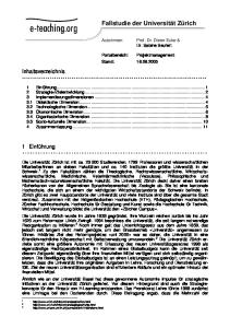
5. Make marks on the base and the router to guide you when mounting the router so that it will correctly face the front of the router table. 6. Remove the router base from the router. 7. Turn the router table mounting board upside down, center the router base on the board so that the marks locating the front of each match. 8. Use the mounting holes in the router base as a template to mark the holes for drilling the holes in the mounting board (see Figure 11 for an example).
Note: There are multiple circles in the underneath surface of the mounting board to aid in centering the router base as a template.
1. DISCONNECT ROUTER FROM POWER! 2. Insert the mounting board into the router table so that the starting pin holes are to the right of the opening, as shown in Figure 10. Starting Pin Holes
Fastener Hole Figure 11. Example of using the router base as a template to drill mounting holes.
3. Mark the front of the mounting board with tape or other removable substance.
If the router unexpectedly moves or the router bit contacts the table insert or fence during operation, serious personal injury could result from the router bit or flying debris. ALWAYS make sure that the router is firmly secured to the router table mounting board before beginning operation.
4. Turn the router upside down and position it so that it is facing you in the same orientation that it will face the front of the router table.
9. Remove the router base from the mounting board, drill the correct size holes in the mounting board for the fasteners.
Figure 10. Proper location of the starting pin holes.
Model T10432 (Mfg. Since 11/10)
-11-
10. Make countersinks in these holes from the top of the mounting board so that the fasteners will be slightly below the top surface of the board. This will prevent the workpiece catching on the fasteners during operation. 11. Turn the router upside down with the mark you made in Step 5 facing you. 12. Position the mounting board, top surface up, so that the mark you made on it in Step 3 is facing you and the mounting holes in the board are aligned with those in the router.
To align the router mounting board and table inserts even with the table: 1. DISCONNECT ROUTER FROM POWER! 2. Remove the fence assembly from the table. 3. Lay the straightedge across the router mounting board and table inserts in a star pattern (see Figure 13) so that both ends are over the table. Table Surface
13. Fasten the mounting board to the router (see Figure 12), then insert the assembly into the router table from the top.
Mounting Board
Straightedge Figure 13. Star pattern for the straightedge when aligning the mounting board with the table.
Figure 12. Example of a router attached to the router table mounting board.
4. Adjust the set screws at the corners of the mounting board (see Figure 14) until the ends of the straightedge lay flat on the table surface at all positions of the star pattern.
Aligning Router Mounting Board To ensure that a workpiece does not catch on the mounting board or table insert and cause a kickback hazard, the board and inserts must be aligned even with the table surface. Qty Tools Needed Hex Wrench 3mm............................................... 1 Straightedge 24"................................................. 1
Set Screw (1 of 4) Figure 14. Using the straightedge on the mounting board and table.
-12-
Model T10432 (Mfg. Since 11/10)
SECTION 3: OPERATIONS Operation Overview The purpose of this overview is to provide the novice machine operator with a basic understanding of how the machine is used during operation, so the machine controls/components discussed later in this manual are easier to understand. Due to the generic nature of this overview, it is not intended to be an instructional guide. To learn more about specific operations, read this entire manual and seek additional training from experienced machine operators, and do additional research outside of this manual by reading "howto" books, trade magazines, or websites.
To complete a typical operation, the operator does the following: 1. Examines the workpiece to make sure it is suitable for cutting. 2. Adjusts the fence boards close to the bit for maximum workpiece support, then secures the fence boards in place. 3. Adjusts the bit height for the desired cutting profile. 4. Adjusts the fence position to establish the depth of cut and makes sure that it is parallel with the table T-slot. 5. Wears safety glasses and a respirator. Locates push sticks or blocks if needed.
To reduce the risk of serious injury when using this machine, read and understand this entire manual before operating.
Damage to your eyes and lungs could result from using this machine without proper protective gear. Always wear safety glasses and a respirator when operating this machine.
6. Verifies that the direction of router bit rotation is correct for the operation, and then starts the router.
7. Holds the workpiece firmly and flatly against the table and fence, then pushes the workpiece into the bit at a steady and controlled rate until the workpiece moves completely beyond the router bit.
NOTICE
Important: For smaller workpieces or oddshaped workpieces, a zero-clearance fence or jig is used.
Important: The operator is very careful to keep the workpiece firmly against the table and fence and hands away from the rotating router bit, during the entire cut.
8. Stops the router.
If you have never used this type of machine or equipment before, We strongly recommend that you read books, review industry trade magazines, or get formal training before beginning any projects. Regardless of the content in this section, Grizzly Industrial will not be held liable for accidents caused by lack of training. Model T10432 (Mfg. Since 11/10)
-13-
Workpiece Inspection Some workpieces are not safe to cut or may require modification before routing. Before routing, inspect all workpieces for the following: •
Foreign Objects: Nails, staples, dirt, rocks and other foreign objects are often embedded in wood. While routing, these objects can become dislodged and hit the operator, cause kickback, or break the bit, which might then fly apart. Always visually inspect your workpiece for these items. If they can't be removed, DO NOT cut the workpiece.
•
Large/Loose Knots: Loose knots may dislodge during a cutting operation. Knots can cause kickback and machine damage. Choose workpieces that do not have large/ loose knots or plan ahead to avoid cutting through them.
•
Wet or "Green" Stock: Routing wood with a moisture content over 20% causes unnecessary wear on the router bits, increases the risk of kickback, and yields poor results.
•
Excessive Warping: Workpieces with excessive cupping, bowing, or twisting are dangerous to cut because they are unstable and often unpredictable when being shaped. DO NOT process workpieces with these characteristics unless you properly square up the stock with a jointer and planer.
•
-14-
To avoid workpiece kickback or binding when using a miter gauge with this router table, ALWAYS make sure the fence boards are parallel with the table T-slot before beginning operation.
Squaring Fence & Table When using a miter gauge, it is important to make sure the fence boards are parallel to the table T-slot. This will help ensure that the workpiece does not bind or kickback during operation. Use a fine ruler to make the distance between the fence boards and the T-slot equal along the full length of the table (see Figure 15 for an example).
Figure 15. Adjusting the fence parallel with the table T-slot.
Minor Warping: Workpieces with slight cupping can be safely supported if the cupped side is facing the table or the fence. A workpiece supported on the bowed side will rock during a cut and could cause kickback or severe injury.
Model T10432 (Mfg. Since 11/10)
Edge Jointing Jointing the edge of a board involves using a straight cutting router bit to remove wood from the face of the board. The result is a perfectly flat and square edge.
Always feed the workpiece against the router bit rotation direction, as illustrated below. Otherwise, the workpiece could be aggressively pulled from your hands, drawing them into the spinning router bit.
Bit Rotation
Workpiece Feed Direction
To joint the edge of a workpiece: 1. DISCONNECT ROUTER FROM POWER! 2. Secure a straight cutting bit into your router according to the router manufacturer's instructions. 3. Install the smallest table insert in the router table that allows the router bit to freely rotate. 4. Raise the bit just above the top of the workpiece, then rotate it by hand until the cutting flute is perpendicular to the fence boards. 5. Secure a shim between the outfeed fence board and fence support. The thickness of the shim controls the amount of material removed with each pass. (see the illustration in Figure 16).
Important: To reduce the risk of kickback, do not take more than 1⁄8" off for any one pass.
Model T10432 (Mfg. Since 11/10)
Top View
Infeed Fence Board
Shim
Outfeed Fence Board
Straight Router Bit Straightedge
Figure 16. Fence setup for edge jointing (guard removed for clarity). 6. Place a straightedge against the outfeed fence board, then adjust the fence assembly so that the straightedge is also against the bit flute, as illustrated in Figure 16. 7. Make sure the fence boards are parallel with the table T-slot, lock the fence assembly in place, and tighten all knobs. 8. Connect the router to power, then perform the cut (see Figure 17).
Top View Shim
Workpiece Cutting Direction Figure 17. Edge jointing (guard removed for clarity).
To reduce the risk of hand injury from accidental contact with the spinning router bit, ALWAYS make sure the fence and router guard are properly positioned and secured before connecting the router to power (does not apply to free hand-hand routing. -15-
Profile Routing To cut a profile into the workpiece: 1. DISCONNECT ROUTER FROM POWER!
5. Make sure both fence boards are even with one another and the table T-slot. 6. Lock the fence assembly in place, tighten all knobs, connect the router to power, then perform the cut.
Routing Small Stock
2. Secure the bit into the router according to the router manufacturer's instructions. 3. Install the smallest table insert into the table that still allows the bit to freely rotate. 4. Raise the bit to the desired height, then adjust the fence assembly so the fence boards are behind the bit the same distance as the desired depth-of-cut (see the illustrations in Figures 18–19).
Feeding small stock past the router bit increases the risk of kickback from the workpiece slipping into the space between the fence and bit. If you must route small stock, use a zero-clearance fence. This will provide greater protection for the operator, better workpiece support, and reduced tear out on narrow or fragile stock. To make a zero-clearance fence:
Top View
1. DISCONNECT ROUTER FROM POWER! 2. Remove the fence boards from the fence support. 3. Select a piece of straight and smooth stock that is the same height and thickness as the fence boards and approximately 36" long.
Depth-of-Cut
Figure 18. Groove cutting setup, top view (guard removed for clarity).
Depth-of-Cut
Note: Make the outline as close as possible to the router bit and spindle without interfering with rotation. Mounting Fastener
Fence
Side View
4. Cut an outline of the spindle and router bit from the center of the stock selected in Step 3, as illustrated in Figure 20.
Zero-Clearance Fence
Bit Table Figure 19. Groove cutting setup, side view (guard removed for clarity). -16-
Table Cutter Figure 20. Example of a zero-clearance fence. Model T10432 (Mfg. Since 11/10)
ALWAYS use hold-downs or featherboards and push sticks when shaping small or narrow stock. These devices keep your hands away from the spinning router bit and sufficiently support the stock to allow a safe and effective cut, reducing the risk of personal injury.
7. Check for proper clearance, connect the router to power, then make a test cut to verify the results.
Irregular or free-hand routing, as illustrated in Figure 21, takes a high degree of skill and dexterity and is done without the protection and aid from the fence and guard. The most dangerous part of free-hand routing is beginning the cut, when the router bit first contacts the workpiece. Often the workpiece will tend to jerk or kickback, presenting an injury hazard to the operator.
Swing Starting Pin Rub Collar
otatio
n
6. Secure the zero-clearance fence to the fence support, then make sure the fence is parallel to the table T-slot.
Free-Hand Routing
R
5. Create countersunk mounting holes in the zero-clearance fence so the bolts, flat washers, and star knobs removed from the fence boards can be used to secure the new fence to the fence support in the same manner.
Workpiece Feed Direction Figure 21. Illustration of free-hand routing using a starting pin (guard not shown for clarity).
Free-hand or irregular routing greatly increases the chance that the operator may lose control of the workpiece, which could result in serious personal injury. Therefore, a starting pin or block and a custom guard or workpiece holding jig MUST be used.
Model T10432 (Mfg. Since 11/10)
-17-
To reduce the likelihood of kickback when freehand routing, use the starting pin or block (see Figures 21–22 for examples). This will allow you to anchor and slowly pivot the workpiece into the bit as the cut is started, making the operation more stable and safe.
3. Remove the fence assembly from the table. 4. If possible, fabricate and mount a custom guard over the bit that safely protects your hands from the spinning router bit. 5. Insert the starting pin in the best suited hole on the routing table or clamp a starting block to the table (see Figure 22 for a generic picture). 6. Install a router bit with a bearing guide as directed by the router manufacturer's instructions, then raise it to the desired height (see Figure 23).
Figure 22. Generic picture of using a jig with a starting block (guard removed for photo clarity).
ALWAYS use an auxiliary jig and extreme care when free-hand routing. Routing without the fence and the attached guard greatly increases the risk of accidental contact with the spinning router bit, causing serious personal injury. To free-hand route: 1. DISCONNECT ROUTER FROM POWER!
Template
Guide Bearing
Workpiece
Figure 23. Using a template and rub collar for free-hand routing. 7. Rest the workpiece against the starting pin, then slowly pivot and feed the workpiece into the bit. After the cut is started, move the workpiece against the guide bearing and away from the starting pin.
2. Fabricate a jig to use with the workpiece that will match the desired finished shape, then attach it to the workpiece (see Figure 22 for an example).
-18-
Note: Make sure any fasteners used will not make contact with the router bit during the cutting operation. Hot glue can be used as an alternative.
Model T10432 (Mfg. Since 11/10)
SECTION 4: MAINTENANCE Always disconnect power to the router before performing maintenance. Failure to do this may result in serious personal injury.
Schedule
Cleaning & Protecting Frequently vacuum sawdust and wood chips from the table and router, then blow off the remaining dust with compressed air. This is especially important for the internal working parts of the fence assembly and the router. Dust build-up around the router is a sure way to decrease its life span.
For optimum performance from your equipment, follow this maintenance schedule and refer to any specific instructions given in this section. Daily Check: • Loose mounting T-bolts or lock knobs. • Worn router switch. • Loose stand fasteners. • Loose router mounting fasteners. • Worn or damaged router cords and plugs. • Any other condition that could hamper the safe operation of this router table.
Model T10432 (Mfg. Since 11/10)
-19-
SECTION 5: PARTS Main Parts Breakdown 47-2 41 46
45
31
47
56 42 44
36 21 27
25
47-3
22
24
31
35 38 37
28 34
5
33
32
26
27
10 9
4 2 6 7
1 3
8 11
-20-
Model T10432 (Mfg. Since 11/10)
Main Parts List REF PART #
DESCRIPTION
REF PART #
DESCRIPTION
1 2 3 4 5 6 7 8 9 10 11 21 22 24 25 26 27 28
LEG LONG BOTTOM STAND BRACE 27-1/4" SHORT BOTTOM STAND BRACE 19-3/4" SHORT TOP STAND BRACE 14-1/2" LONG TOP STAND BRACE 22-1/4" CARRIAGE BOLT M8-1.25 X 12 HEX NUT M8-1.25 FLAT WASHER 8MM HEX BOLT M6-1 X 16 FLAT WASHER 6MM RUBBER FOOT FENCE SUPPORT DUST PORT HOUSING PHLP HD SCR M5-.8 X 55 DUST PORT TRI-KNOB M6-1 MITER SLOT TRACK HEX BOLT M8-1.25 X 25
31 32 33 34 35 36 37 38 41 42 44 45 46 47 47-2 47-3 56
WOOD SCREW #4 X 1/2 FENCE GUARD HEX BOLT M8-1.25 X 25 STAR KNOB M8-1.25 FENCE SCALE TAPE FLAT WASHER 6MM T-BOLT M6-1 X 25 TABLE TOP 31-1/2" X 24" MITER SLOT TRACK 31-1/2" HEX BOLT M6-1 X 16 MITER SLOT TRACK 11-3/4" SET SCREW M6-1 X 6 ROUTER MOUNTING BOARD GUIDE PIN MAGNET 4-PC HEX WRENCH 3MM
PT10432001 PT10432002 PT10432003 PT10432004 PT10432005 PCB11M PN03M PW01M PB83M PW03M PT10432011 PT10432021 PT10432022 PS104M PT10432025 PT10432026 PT10432027 PB07M
Model T10432 (Mfg. Since 11/10)
PWS007 PT10432032 PT10432033 PB07M PT10432035 PT10432036 PW03M PT10432038 PT10432041 PT10432042 PB83M PT10432045 PSS02M PT10432047 PT10432047-2 PT10432047-3 PAW03M
-21-
Labels Parts List
51
55
54
52
53
REF PART #
DESCRIPTION
REF PART #
DESCRIPTION
51 52 53
ID LABEL AMPUTATION HAZARD LABEL GLASSES/RESPIRATOR LABEL HS
54 55
READ MANUAL LABEL HS BLACK TOUCH-UP PAINT
-22-
PT10432051 PT10432052 PLABEL-57C
PLABEL-12D PPAINT-7
Model T10432 (Mfg. Since 11/10)
WARRANTY CARD Name _____________________________________________________________________________ Street _____________________________________________________________________________ City _______________________ State _________________________ Zip _____________________ Phone # ____________________ Email _________________________________________________ Model # ____________________ Order # _______________________ Serial # __________________ The following information is given on a voluntary basis. It will be used for marketing purposes to help us develop better products and services. Of course, all information is strictly confidential.
1.
CUT ALONG DOTTED LINE
2.
How did you learn about us? ____ Advertisement ____ Card Deck
4.
5. 6.
____ Catalog ____ Other:
Which of the following magazines do you subscribe to?
____ ____ ____ ____ ____ ____ ____ ____ ____ ____ 3.
____ Friend ____ Website
Cabinetmaker & FDM Family Handyman Hand Loader Handy Home Shop Machinist Journal of Light Cont. Live Steam Model Airplane News Old House Journal Popular Mechanics
____ ____ ____ ____ ____ ____ ____ ____ ____ ____
Popular Science Popular Woodworking Precision Shooter Projects in Metal RC Modeler Rifle Shop Notes Shotgun News Today’s Homeowner Wood
____ ____ ____ ____ ____ ____ ____
Wooden Boat Woodshop News Woodsmith Woodwork Woodworker West Woodworker’s Journal Other:
What is your annual household income? ____ $20,000-$29,000 ____ $30,000-$39,000 ____ $50,000-$59,000 ____ $60,000-$69,000
____ $40,000-$49,000 ____ $70,000+
What is your age group? ____ 20-29 ____ 50-59
____ 40-49 ____ 70+
____ 30-39 ____ 60-69
How long have you been a woodworker/metalworker? ____ 0-2 Years ____ 2-8 Years ____ 8-20 Years
____ 20+ Years
How many of your machines or tools are Grizzly? ____ 0-2 ____ 3-5 ____ 6-9
____ 10+
7.
Do you think your machine represents a good value?
_____ Yes
_____No
8.
Would you recommend Grizzly Industrial to a friend?
_____ Yes
_____No
9.
Would you allow us to use your name as a reference for Grizzly customers in your area? Note: We never use names more than 3 times. _____ Yes _____No
10. Comments: _____________________________________________________________________ _________________________________________________________________________________ _________________________________________________________________________________ _________________________________________________________________________________
FOLD ALONG DOTTED LINE
Place Stamp Here
GRIZZLY INDUSTRIAL, INC. P.O. BOX 2069 BELLINGHAM, WA 98227-2069
FOLD ALONG DOTTED LINE
Send a Grizzly Catalog to a friend: Name_______________________________ Street_______________________________ City______________State______Zip______ TAPE ALONG EDGES--PLEASE DO NOT STAPLE
WARRANTY AND RETURNS WARRANTY AND RETURNS Grizzly Industrial, Inc. warrants every product it sells for a period of 1 year to the original purchaser from the date of purchase. This warranty does not apply to defects due directly or indirectly to misuse, abuse, negligence, accidents, repairs or alterations or lack of maintenance. This is Grizzly’s sole written warranty and any and all warranties that may be implied by law, including any merchantability or fitness, for any particular purpose, are hereby limited to the duration of this written warranty. We do not warrant or represent that the merchandise complies with the provisions of any law or acts unless the manufacturer so warrants. In no event shall Grizzly’s liability under this warranty exceed the purchase price paid for the product and any legal actions brought against Grizzly shall be tried in the State of Washington, County of Whatcom. We shall in no event be liable for death, injuries to persons or property or for incidental, contingent, special, or consequential damages arising from the use of our products. To take advantage of this warranty, contact us by mail or phone and give us all the details. We will then issue you a “Return Number,’’ which must be clearly posted on the outside as well as the inside of the carton. We will not accept any item back without this number. Proof of purchase must accompany the merchandise. The manufacturers reserve the right to change specifications at any time because they constantly strive to achieve better quality equipment. We make every effort to ensure that our products meet high quality and durability standards and we hope you never need to use this warranty. Please feel free to write or call us if you have any questions about the machine or the manual. Thank you again for your business and continued support. We hope to serve you again soon.