TURNING
SR-Series Heavy-Duty Universal Chuck and Bar Turning Centers
TURNING MILLING GRINDING WORKHOLDING
www.hardinge.com
Unique features that make the SR-Series the best in the industry!
SR-Series Heavy-Duty, Universal Chuck and Bar CNC Turning Centers
Featuring our world-famous spindle, delivering unparalleled performance
SR-Series chuck and bar machines redefine the meaning of strength and reliability, creating a new benchmark in the industry for turning centers utilizing a 3-jaw chuck. Well known for superior spindle design and construction, Hardinge now adds the all-new heavy-duty SR machines to its line-up of multi-functional turning centers. The SR’s superior vibration damping is accomplished through the use of heavy-duty linear roller guides mounted to a HARCRETE-reinforced cast iron base, allowing you to tackle the toughest work virtually vibration free while reducing your expenditure on today’s high-performance tooling.
Rigid machine base See page 4
Heavy-duty roller guideways, ballscrews and axis drives See page 5
Powerful and rigid spindle See page 6
SR 150 and SR 200
SR machines offer superior features and performance for both job shops and production environments. The machines can be configured for 2-axis turning or for complex multi-tasking operations in a single set-up.
So whether it’s heavy-metal removal in low or high-volume production, the new SR machines will allow you to work with confidence to get your jobs done for less!
2
Unique ESA turret top plate and tooling system option See page 8
www.hardinge.com
Standard features include: • Powerful and rigid spindle with 3-jaw chuck • Rigid HARCRETE®-reinforced cast iron base • 187-psi through-tool coolant • Heavy-duty roller guideways, ball screws and axis drives • Environmentally-friendly grease lubrication • Linear glass scale (X-axis) • User-friendly pendant-mounted control • Manual Guide i programming • Ethernet connectivity
3
Heavy-duty roller guideways, ballscrews and axis drives create the optimum performance characteristics
SR-Series Heavy-Duty, Universal Chuck and Bar CNC Turning Centers Rigidity that is built like a rock from the ground up
Rigid machine base Our rugged cast iron bases with HARCRETE® polymer composite (synthetic granite) reinforcement offer added stiffness with superior damping characteristics of vibration to the workpiece for finer surface finishes and 30% longer tool life.
Heavy-duty roller guideways, ballscrews and axis drives Wide-spaced, oversized roller guideways offer superior stiffness and rigidity with less friction, less heat and less thermal growth for faster traverse rates, longer machine life and greater positioning accuracy. The roller way modules consist of slide members (guide trucks) and roller rails to provide high rigidity and low friction. The spacing between the Z-axis rails provides optimum stiffness for the overall machine design. Oversized 1.57”/40mm ballscrews are featured. Torque limiters are provided as standard equipment.
Z-Axis roller guideway
Linear glass scale
FEA (Finite Element Analysis) FEA (finite element analysis) techniques were used to design a rigid, structurally balanced machine, resulting in superior damping characteristics for minimized vibration to the workpiece, heavy cutting capability, extended tool life and fine surface finishes. X-Axis linear scale
4
5
www.hardinge.com
A Heidenhain linear scale is provided on the X-axis for high machining performance over a large number of parts. The closedloop linear scale system for positioning accuracy provides direct measurement to compensate for ball screw thermal growth and wear over the life of the machine.
Wide range of optional equipment to increase your productivity
SR-Series Heavy-Duty, Universal Chuck and Bar CNC Turning Centers Unprecedented performance characteristics
Powerful and rigid spindle
Polygon turning
Tailstock
When used with live tooling, this feature allows cutting square, hexagon or other polygon shapes on workpiece ODs.
Our powerful main spindle drive provides all the power and torque you’ll need to do heavy turning, drilling and rigid tapping operations. Hardinge-built spindles are hardened & ground and of one-piece construction. They are mounted in a highstrength cast iron headstock housing and mounted to the HARCRETE-reinforced cast iron base for optimum stiffness, rigidity and damping. In addition, a labyrinth seal shields coolant from the spindle bearings. This design accommodates the use of higher pressure coolant systems.
C-Axis contouring (main and sub spindle) Polar, cylindrical and 3-axis interpolation allows unlimited machining capabilities when used with the live tooling option—positioning increments of .001 degree (C-Axis is standard on SR M, SR MS and SR MSY models). Sub spindle (part present sensor shown)
A2-5 Sub spindle E
OM TO C NEW
Continuous air flow
The sub spindle offers a thru-capacity up to 15⁄8”/42mm with 16C collets and a gripping capacity of 51⁄2”/139mm with 6”/150mm jaw chucks. Exact synchronization between the main and sub at any rpm can be programmed for part transfer for secondary machining.
Additional optional features include:
Headstock Cooling
6
On-the-fly part transfer between main and sub spindle
Out-of-the-box automation solutions
Parts catcher
High-precision option: • Real time thermal compensation algorithm • Up to .000030” part roundness capability • Linear Glass scales on the X and Z axes • .000010”/.0001mm programmable resolution/ tool offset capability • Fully ball-bar tested for accuracy • Laser compensated in both X and Z axes • Tested on a chuck spindle machine
Exclusive Hardinge technological feature available: • HydroGlide Hydrostatic Guideways— machines equipped with high-precison option only
Parts conveyor
7
www.hardinge.com
The spindle incorporates a unique “thermocentric” design that provides exceptional thermal stability for increased part accuracy. The design utilizes principles of symmetry and thermal isolation to minimize the transfer of heat generated by the spindle bearings into the cast iron machine structure. The spindle head incorporates a “winged” construction that rigidly connects it to a cast iron riser for maximum rigidity and minimum thermal contact area. The unique symmetry of the design allows the spindle head to warm up without affecting location of the spindle centerline. Air blows through the riser to cool the spindle, minimizing its expansion. The air then flows through a space between the spindle head and riser, cooling the spindle structure and removing heat before the air can migrate to the riser. The thermal expansion error associated with machine warm-up is greatly diminished, effectively by isolating the warm spindle head and limiting the heat that could have transferred to the cast iron structure.
• ESA 12-station top plates • Hardinge T-style 10- and 12-station top plates • Part probe • Automatic tool touch probe • Air blast system (main spindle) • 1,000-psi High-pressure coolant • Thru-spindle coolant (main or sub spindle) • Sub spindle parts catcher • Chip conveyor • Bar feed systems • Power transformers • 3-Position stack light • Manual VDI tool presetter system
Hardinge’s exclusive ESA turret top plate and tooling system
SR-Series Heavy-Duty, Universal Chuck and Bar CNC Turning Centers Turret top plate and tooling systems to enhance your throughput capability
A VDI turret top plate is standard equipment on SR turning centers—with or without live tooling and Y-axis options. The optional ESA (Eppinger Self Alignment) turret and top plate and tooling system is available for increased tool rigidity. A Hardinge T-style top plate for static tooling compatibility with QUEST® and CONQUEST® T42/T51/T65 lathes equipped with a T-style top plate is also available.
Optional ESA top plate
Standard VDI top plate
Ground face Ground ring Tool clamp
Live tooling This option is available on VDI 30 and ESA top plates to work on the main spindle or sub spindle (standard on SR M, SR MS and SR MSY models). Each station can be equipped with a driven tool for cross- or end-milling/drilling operations in the toughest materials. One-degree spindle orient is included. Internal and external coolantstyle live tool holders are offered to direct coolant to the work area. Angular drilling or milling is easily accomplished using adjustable live tooling attachments. Air/oil mist lubrication is included.
Minimal VDI tool interference B End Mill/Drill Double Spindle Attachment
F P
B
3/4" Tool Holder
G
1.25"
M
O N
L .88"
M
B
K M
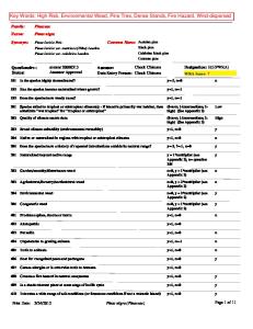
Perform thread milling and complex offcenter milling and drilling operations on either the main or sub spindle option— 3.38”/85.6mm overall travel!
Cut-Off Tool Holder
B
The illustration represents the maximum part diameters that can clear adjacent tool holders.
L J I
Diameter A B C D E F G H I
Dimension 9.46"/240.3mm 9.18"/233.2mm 8.71"/221.2mm 9.36"/237.7mm 9.39"/238.5mm 8.13"/206.5mm 8.53"/216.7mm 8.06"/204.7mm 8.70"/221.0mm
8
H
B
End Mill/Drill Double Spindle Attachment
Diameter J K L M N O P Q
Dimension 7.90"/200.7mm 9.36"/237.7mm 2.75"/70.0mm 3.46"/88.0mm 9.66"/245.4mm 9.41"/239.0mm 8.32"/211.3mm 8.72"/221.5mm
Experience 3 to 5 times longer tool life with the PRECI-FLEX spindle and adapter system Run out adapter: < .00078“ / < 0.002mm Run out tool tip (shrink fit type): < .00012“ / < 0.003mm Tool change: < 60 sec Repeatability: < .00012“ / < 0.003mm Tool clamping force: > 4 x collet Chip removal volume: > 2 x collet Increased insert/tool life: + 3-5 X
www.hardinge.com
Rigid tapping is standard capability on the main spindle and sub spindle option, as well as cross- and face-working operations on machines equipped with the live tooling option.
Cross Mill/Drill Attachment
L
Y-Axis option
Rigid tapping
End Mill/Drill Attachment
Q
9
User-friendly software to unleash your productivity
SR-Series Heavy-Duty, Universal Chuck and Bar CNC Turning Centers All the control you’ll ever need right at your fingertips
Hardinge GE Fanuc i Series SR controls feature many standard multi-tasking capabilities other machine tool builders charge extra for—graphic toolpath display, rigid tapping, tool life management, stored stroke check 2 & 3, variable lead thread cutting, and run time and parts counter.
General Two Interpolating Axes Programmable Resolution—.00010”/.0010mm (Super-Precision® Models— .000010”/.00010mm) Tool Offset Capability—.00010”/.0010mm (Super-Precision Models— .000010”/.00010mm) Inch/Metric Data Selection by G-Code 160 Meters Part Program Storage Part Program Storage (320, 640 or 1,280 meters total) Data Input/Output MDI (Manual Data Input) Operation Reader/Punch Interface (RS-232 Software/Hardware)
O
• • • • • • • • • • • • • • • • • O
Operation Block Delete Dry Run Dwell Time Emergency Stop Feed Hold Feedrate Override (0 to 150%) Incremental Jog Jog Feed
10
O
• • • • • • O
O O
Operation (cont’d) Machine Lock Manual Pulse Generator (MPG) On-Screen Spindle & Axis Load Meters Option Stop Rapid Traverse Override (Low-25-50-100%) Spindle Speed and T-Code Displays on All Screens Tool Geometry and Tool Wear Offsets — (32 pairs each)
• • • • • • • • • • • • • • • • • • • • O
O
Miscellaneous Actual Cutting Speed Display C-Axis with Polar and Linear Interpolation Color LCD Display with Full Keyboard — English French/German, Italian or Spanish Ethernet Card Flash Card Capability Ladder Diagram Display Mechanical Run Meter On-Screen “HELP” Functions for Alarms One-Degree Spindle Orient 2 PC Front-End Control Program Protect Run Time and Parts Counter Self-Diagnosis Function Stored Pitch Error Compensation Y-Axis with offsets (32 pair) 3D Coordinate System Conversion— Y-Axis with Angular Tool
Manual Guide i is an advanced conversational programming system. A fully animated version of the operator-generated part program can be easily viewed on the large full-color display. Using Manual Guide i ensures that the process is proven prior to actual machining. If desired, the simple push of a button converts the conversational program into a standard G- and M-code program.
• • • • • • • • • • • • • • • • • • O
O
O O
O
www.hardinge.com
Programming Functions Absolute/Incremental Programming Additional Tool Offsets (32 pair total) Additional Custom Macro Variables Auto Coordinate System Setting Auto Acceleration/Deceleration Background Editing Canned Cycles (Drilling) Chamfer/Corner Rounding Constant Surface Speed Programming Continual Thread Cutting Coordinate System Setting (G50) Custom Macro B Decimal Point Programming Diameter/Radius Programming Direct Drawing Dimension Programming Exact Stop
• • • • • • •
Programming Functions (cont’d) Extended Part Program Edit External Workpiece Number Search Graphic Toolpath Display Hardinge Safe Start Format Helical Interpolation Input of Offset Value by Programming (G10) Interpolation (Linear and Circular) Multiple Repetitive Canned Cycles I (Turning) Multiple Repetitive Canned Cycles II (Pockets) Polygon Turning Software 1 Program Number Search Reference Point Return Registered Part Programs (63 total) Registered Part Programs — (125, 200 or 400 total) Rigid Tapping Sequence Number Search Single Block Operation Stored Stroke Check 2 & 3 Thread Cutting Cycle Retract Thread, Synchronous Cutting Tool Life Management Tool Nose Radius Compensation Variable Lead Thread Cutting
Manual Guide i
O
Standard O Optional
1 - Hardware package suggested 2 - Included with Live Tooling Option
11
The Hardinge® Group… Bridgeport® milling machines, Hardinge turning centers, Hauser, Kellenberger®, Tripet and Tschudin grinding machines, and Workholding and industrial products
SR-Series Heavy-Duty, Universal Chuck and Bar CNC Turning Centers Choose the machine variation that suits your current and future needs
SR 150 • A2-6 spindle nose • 6-Inch jaw chuck • 20-hp/15-kW spindle drive system • 211ft-lb/286Nm torque • 6,000-rpm spindle speed • Hardinge/GE Fanuc i Series SR control
SR 200 • A2-6 spindle nose • 8-Inch jaw chuck • 30-hp/26-kW spindle drive system • 270ft-lb/365Nm torque • 4,500-rpm spindle speed • Hardinge/GE Fanuc i Series SR control
12
Whether you are an OEM or sub-contract precision engineering company—regardless of the sectors you serve (aerospace, automotive, medical, autosport, mold tool and die or general engineering)—the Hardinge product portfolio will interest you. Our advanced manufacturing technologies in combination with our range of aftersales and support services (maintenance and service contracts; operator training; technical and applications support) have been designed to help you improve your performance and maintain your competitive advantage. If you would like to know more about our manufacturing solutions, call us at 800.843.8801 or 607.734.2281 and request our Pocket Guide #1325. You can also e-mail us at
[email protected] or visit our web site at www.hardinge.com.
Hardinge precision and Super-Precision® CNC turning centers We can help you turn your business around. From our competitively-priced SV-Series range of machines to our TALENT® and ELITE® Series II range of quickchangeover bar and chucking machines right through to our high-productivity QUEST® GT gang tool and multi-tasking machines, we can provide you with the optimum turning solution. Milling machines and machining centers Our comprehensive line of Bridgeport milling machines have been designed to meet any manufacturing challenge you might be facing today or in the future. Our marketleading XR range of vertical machining centers continue to grow in popularity— and we have similar expectations with our new competitively-priced XV and GX VMCs as well. For heavy-duty, high metal removal we offer our HMC range of Horizontal Machining Centers and for increased manufacturing flexibility and improved productivity there's our 5-axis (5AX) model that is well worthy of consideration. If you are making your first step up to CNC machining, you will find that our entry-level GX 480 and GX 480 DT machines provide the ideal solution. For high-speed machining applications, our HSC machining centers are second to none. 13
Grinding machines The Hardinge grinding companies include Hauser, Kellenberger, Tripet, Tschudin and, most recently, Bridgeport. Collectively we have all the technology, experience and knowhow you need to transform your manufacturing operations. From highperformance cylindrical and jig grinding machines through to multi-functional ID/OD and universal machines—not to mention Bridgeport's state-of-the-art Flexible Grinding Centers (FGC 2). It doesn't get more comprehensive than this. Workholding Because we design and manufacture market-leading, technically-excellent machine tools it's no surprise that we know more than a thing or two about workholding solutions. From our extensive portfolio of CNC toolholders, collets and chucks—right through to our 5C Indexing systems—our workholding and fixturing technology will improve your performance when and where it matters most.
www.hardinge.com
S—Sub Spindle M—Live Tooling & C-Axis MY—Live Tooling, C-Axis & Y-Axis MS—Live Tooling, Sub Spindle & C-Axis (both spindles) MSY—Live Tooling, Sub Spindle, Y-Axis & C-Axis (both spindles) Machine name example: SR 200 MSY
Hardinge produces more than just the SR-Series turning centers shown in this brochure…we build a full range of valuepacked and high-precision turning centers; vertical and horizontal machining centers; high-speed and 5-axis milling machines; creep-feed, jig, universal cylindrical and ID/OD grinding machines; and workholding systems and equipment. Hardinge machine tool technology is not only the most comprehensive on the market, it's also creating new benchmarks for quality, productivity and reliability.
SR-Series Heavy-Duty, Universal Chuck and Bar CNC Turning Centers Specifications that set a new benchmark for competitive machines
SR 150
SR 200
Programmable Resolution/Tool Offset Capability
.00010”/.0010mm
.00010”/.0010mm
Spindle—Configuration (ANSI) Spindle Through-Hole Bar Capacity Jaw Chuck Size Turning Length (Max.) Spindle Centerline Height Spindle Reach
A2-6 2.64”/66.0mm 2”/51mm 6”/150mm 20.50”/520.7mm 41.00”/1041.4mm 18.70”/475.0mm
A2-6 3.15”/80.0mm 2.50”/65mm 8”/200mm 20.10”/510.5mm 41.00”/1041.4mm 18.70”/475.0mm
AC Digital Belted Drive System Base Speed Power Rating at Base Speed Torque Rating at Base Speed Speed Range (1-rpm steps)
1
500-750 rpm 5 20hp/15kW 211-141ft-lb/286-191Nm 60 to 6,000
Carriage and Cross Slide Swing Diameter Over Way Cover Turning Diameter (Max.) VDI Turret 3 Conventional T-Style Turret Option ESA Turret Option 3 Travels (Max.) X-Axis Z-Axis Y-Axis Option Traverse Rates (Max.) X-Axis Z-Axis Z-Axis with HydroGlide Option 3A Y-Axis Option Thrusts (Max.) Z-Axis Z-Axis with HydroGlide Option 3A Y-Axis Option Inspection Specifications 6 Part Surface Finish Overall Axis Repeatability
5
20.44”/519.2mm
20.44”/519.2mm
12.28”/311.9mm 14.05”/356.8mm 12.65”/321.3mm
12.28”/311.9mm 14.05”/356.8mm 12.65”/321.3mm
7.45”/189.2mm 21.94”/557.3mm +2.00 to -1.377”/+50.8 to -34.9mm
7.45”/189.2mm 21.54”/547.1mm +2.00 to -1.377”/+50.8 to -34.9mm
1,100ipm / 28m/min 1,500ipm / 38m/min 2,300ipm / 58m/min 375ipm / 9.5m/min
1,100ipm / 28m/min 1,500ipm / 38m/min 2,300ipm / 58m/min 375ipm / 9.5m/min
2,250lb/10,000N 1,800lb/8.007N 1,175lb/5,227N Precision Model 12 micro-inch/.30 micron .000050”/1.27 micron High-Precision Option 10 micro-inch/.25 micron .000050”/1.27 micron .0002”/5 micron
2,250lb/10,000N 1,800lb/8.007N 1,175lb/5,227N Precision Model 12 micro-inch/.30 micron .000050”/1.27 micron High-Precision Option 10 micro-inch/.25 micron .000050”/1.27 micron .0002”/5 micron
.000030”/.76 micron
.000030”/.76 micron
3
Part Surface Finish Part Roundness Part Continuous Machining Accuracy (Total Variation on Diameter) Overall Axis Repeatability
575 rpm 30hp/26kW 270ft-lb/365Nm 45 to 4,500
10.14”/ 257.6mm
117.78”/2991.6mm
134.63”/3419.6mm
164.99”/4190.8mm
14
47.20” 1198.9mm
42.24” /1072.9mm
77.71”/1973.8mm
90.14”/2289.6mm
76.15”/1934.2mm
116.05”/2947.7mm
28.61”/ 726.7mm
SR 200
12 Stations 1” / 25mm 11/ 2 ” / 40mm 0.1 Second 16 Stations
12 Stations 1” / 25mm 11/ 2 ” / 40mm 0.1 Second 16 Stations
.062 to .625”/2 to 16mm 5hp/3.7kW 17.4ft-lb/23.6Nm 80 to 8,000
.062 to .625”/2 to 16mm 5hp/3.7kW 17.4ft-lb/23.6Nm 80 to 8,000
10 or 12 Stations 1” / 25mm 11/ 2 ” / 40mm .35 Second 12 Station 1” / 25mm 1 1 / 4” / 32mm .35 Second
10 or 12 Stations 1” / 25mm 11/ 2 ” / 40mm .35 Second 12 Station 1” / 25mm 1 1 / 4” / 32mm .35 Second
.062 to .625”/2 to 16mm 5hp/3.7kW 17.4ft-lb/23.6Nm 80 to 8,000
.062 to .625”/2 to 16mm 5hp/3.7kW 17.4ft-lb/23.6Nm 80 to 8,000
Sub Spindle Option 1, 2 Spindle Configuration (ANSI) Round 16C Collet (Through Capacity) Jaw Chuck Size Step Chuck (Gripping Capacity) Power Rating @ 1,500-rpm Base Speed Torque Rating Speed Range (1-rpm steps) Travel (Max.) 9 Traverse Rate (Max.)
A2-5, 16C 1.625”/42mm 6”/150mm 6”/152.4mm 10hp/7.5kW 35ft-lb/47.7Nm 60 to 6,000 18.70”/475.0mm 1,500ipm / 38m/min
A2-5, 16C 1.625”/42mm 6”/150mm 6”/152.4mm 10hp/7.5kW 35ft-lb/47.7Nm 60 to 6,000 17.90”/454.7mm 1,500ipm / 38m/min
Hydraulic Tailstock Option 2 Part Length (Max.) Travel (Max.) Traverse Rate (Max.) Hydraulic Applied Force (Min. to Max.)
MT 4 20.00”/508.0mm 21.50”/546.1mm 300ipm / 7.6m/min 630 to 1,570lb/280 to 700daN
MT 4 19.20”/487.7mm 21.50”/546.1mm 300ipm / 7.6m/min 630 to 1,570lb/280 to 700daN
230v/3 Phase/112FLA 50gal/189liter 187psi/12.9bar 6.75gpm / 25.5l/min 1,000psi/98.95bar
230v/3 Phase/135FLA 50gal/189liter 187psi/12.9bar 6.75gpm / 25.5l/min 1,000psi/98.95bar
117.78"/2991.6mm 164.99"/4190.8mm 90.14"/2289.6mm 77.71"/1973.8mm 15,086lb/6,843kg 15,686lb/7,115kg
117.78"/2991.6mm 164.99"/4190.8mm 90.14"/2289.6mm 77.71"/1973.8mm 15,486lb/7,024kg 16,086lb/7,961kg
Bidirectional Turret Top Plate VDI 30 Tool Configuration Square Shank Tool Size (Max.) Round Shank Tool Size (Max.) Indexing Time (Station-to-Station) VDI 30 16-Station Tool Configuration Option VDI 30 Live Tooling Option—All Stations 2 Tool Shank Diameter w/ER25 Collets Power Rating at Tool Tip 7 Torque Rating at Tool Tip 8 Speed Range (1-rpm Steps) Conventional Hardinge T-Style 2 Turret Top Plate Option (Inch or Metric) Square Shank Tool Size (Max.) Round Shank Tool Size (Max.) Indexing Time (Station-to-Station) ESA Tool Configuration Option 2 Square Shank Tool Size (Max.) Round Shank Tool Size (Max.) Indexing Time (Station-to-Station) ESA Live Tooling Option—All Stations 2 Tool Shank Diameter w/ER25 Collets Power Rating 1 Torque Rating 1 Speed Range (1-rpm Steps)
2, 4
Miscellaneous Power Supply Requirement 10 Coolant Tank Capacity Coolant Pressure Coolant Flow Rate High-Pressure Thru-Tool Coolant Option Machine Dimensions Length Length with Chip Conveyor Option Depth Height Weight (Approx.) Shipping Weight (Approx.) 1—30-minute intermittent ratings used for power and torque specifications. 2—Available as original equipment only. 3—Actual dimension based on tool overhang. 3A—Available only on machines equipped with the High-Precision option. 4—Tool clearance affected by part diameter.
5—Low/high range listed. 6—Results were derived from actual tests conducted at Hardinge. Due to varying cutting conditions, actual results may be greater or less than those listed. 7—15-minute rating. 8—30% duty cycle (3-minute rating).
15
9—Maximum distance between spindle and jaw chuck faces. 10—FLA shown for base machine. NOTE: A supplementary power transformer is required for all voltages other than 230v, 50/60Hz.
www.hardinge.com
119.29”/3030.0mm
Floor plan
SR 150
Over the past 10 years Hardinge steadily diversified both its product offerings and operations.Today, the company has grown into a globally diversified player with manufacturing operations in the U.S., Switzerland, China and Taiwan. In addition to designing and building turning centers and collets, Hardinge is a world leader in grinding solutions with the addition of the Kellenberger, Hauser, Tripet and Tschudin brands to the Hardinge family.The company also manufactures Bridgeport machining centers and other industrial products for a wide range of material cutting, turnkey automation and workholding needs.
Expect more from your Hardinge products. Choose Hardinge precision and reliability for increased productivity and value!
Call us today, we’ve got your answer.
Hardinge Inc. One Hardinge Drive | P.O. Box 1507 | Elmira, New York 14902-1507 USA USA: 800.843.8801 | Canada: 800.468.5946 | Phone: 607.734.2281 | Fax: 607.734.8819 Corporate Web Site: www.hardinge.com | E-mail:
[email protected] All specifications subject to change without notice. All marks indicated by ® and ™ are trademarks of their respective owners Brochure #1358 • Litho in USA • ©Hardinge Inc. 2005 • 7.5M February 2007