Specifications Overall Dimensions Batteries
Page 2
3-3/4" L x 13-3/4" W x 20-5/8" H 4 - AA (sold separately)
For technical questions, please call 1-800-444-3353.
Item 97081
IMPORTANT SAFETY INFORMATION Installation Precautions 1. Verify that installation surface has no hidden utility lines before drilling or driving screws. 2. Wear ANSI-approved safety goggles during installation. 3. Mount securely before use. 4. Install only according to these instructions. Improper installation can create hazards.
6. Keep bystanders out of the area during installation. 7. Do not install when tired or when under the influence of alcohol, drugs, or medication. 8. Do not expose to rain. For indoor use only. 9. After installation, make certain that the Wall Safe is mounted securely. Mounting surface must be able to support the Digital Wall Safe and its contents.
5. Keep installation area clean and well lit.
Use Precautions 1. Keep closed and locked whenever unattended. Check inside before closing. Do not allow children to play with or near safe. Keep keys and codes away from children.
7. Do not store Keys inside of the Safe. Place the emergency keys in a location outside of the safe making sure they are in a secure location that you can find.
2. Keep clear of door when closing.
8. Warning: The brass components of this product contain lead, a chemical known to the State of California to cause birth defects (or other reproductive harm). (California Health & Safety code § 25249.5, et seq.)
3. Position batteries in proper polarity and do not install batteries of different types, charge levels, or capacities together. 4. Use as intended only. 5. Inspect before every use; do not use if parts are loose or damaged. 6. Maintain product labels and nameplates. These carry important safety information. If unreadable or missing, contact Harbor Freight Tools for a replacement.
9. Do not exceed the 99 lb maximum weight capacity for the Wall Safe. 10. The warnings, cautions, and instructions discussed in this instruction manual cannot cover all possible conditions and situations that may occur. It must be understood by the operator that common sense and caution are factors which cannot be built into this product, but must be supplied by the operator. 11. The Safe is neither water nor fire proof.
NOTE: Harbor Freight Tools is not responsible for the loss of any property stored within this safe due to theft, fire, or any other circumstance.
Item 97081
For technical questions, please call 1-800-444-3353.
Page 3
Installation
WARNING
To prevent structural damage and possible collapse of the building: Do not cut or alter studs to fit the Safe. If the wall the Safe is to be installed in is a load bearing wall, professional installation is required. Note: The instructions below apply only to installation in a wall with wood studs. Installation involving a different type of wall will require other procedures or professional installation. 1. Choose a wall in which to mount the Safe. A wall that does not border the outside of the structure will provide an added layer of security. The four Screws are for mounting in concrete or masonry. If you are going to mount the Safe on another surface, you must supply the appropriate hardware.
4. Wall studs are generally located at 16" intervals, center stud to center stud. Use a Stud Finder (not included) to locate existing studs. If the existing studs are not located at 16" intervals, use wood blocks or top and bottom support brackets (not included) to support the Wall Safe. 5. Use a piece of paper to create a template using the back of the Wall Safe. Once you have created the template, set it at the desired space on the wall. Use a carpenter’s level to set the template evenly in place. 6. Make certain the work area is free of furniture and any items that may be damaged by dust from drilling. Turn off the circuit breaker for the area you are working in to avoid electrocution. 7. Hammer a nail into the center of the wall section to be removed. Use a drywall saw or jig saw to cut out the section of wall as outlined by the template. Depending on the depth of the Safe in relation to the depth of walls, you may need to cut through two walls – the wall nearest you and the one behind it. Use the nail as a handle when pulling out the cut portion of the wall.
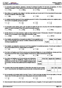
Mounting Holes
Figure A 2. There are pre-drilled holes in each side of the Wall Safe meant for mounting between two wall studs-see Figure A. Before mounting or drilling, make certain that the space the Safe will be mounted in is of sufficient depth and width to encase the Wall Safe.
8. Situate the Safe in its intended position and draw marks through the four mounting holes onto the studs. Remove the Safe and use those marks to predrill pilot holes for the Screws. 9. Set the Safe in place. If it does not fit snugly, use shims to wedge it in place. Shims can be nailed to the wall studs. 10. Thread the Screws into place.
WARNING! Verify that the installation location has no hidden utility lines before cutting, drilling, or driving screws. 3. Open the Safe by using the included key. Install 4 “AA” batteries aligned with the markings in the battery compartment. Set up a pass code, as explained in the Operation Instructions.
Pin
Shelf
Figure B 11. Secure Shelves in place as shown in Figure B by inserting Pins through the holes in the ends of each Shelf.
Page 4
For technical questions, please call 1-800-444-3353.
Item 97081
Operation
Components
Wall Safe
Key Pad Mounting Holes
Shelf Keyhole Cover
Door
Figure C
Item 97081
For technical questions, please call 1-800-444-3353.
Page 5
Opening the Wall Safe 1. The Wall Safe is delivered with a preset, temporary pass code.
4. When the green light goes on, turn the knob to open the Wall Safe.
2. The temporary pass code is either 159A or 159B.
5. If the green light does not go on, and the yellow light continues to blink, this indicates that the wrong code was entered. Wait 20 seconds to input the pass code.
3. On the Key Pad (see Figure D), enter the temporary pass code. The yellow light on the LED will flash when each number is entered. The green light will light up when the Wall Safe is ready to be opened.
Using the Override Key If the batteries have not been installed or are worn out, open the safe using one of the Override Keys. Key Pad
1. Gently detach the panel covering the Key Hole (see Figure D). 2. Insert the Override Key into the lock and turn. Turn the knob and pull the door open.
Override Key and Keyhole Figure D
Important: Never lock your Override Keys inside the safe. Store them separately in a safe place.
Programming a Pass Code 1. Locate the Memory Button on the inside of the Door. 2. Using a blunt tip such as the tip of a screwdriver or pen, push and release the Memory Button. 3. When you hear a “beep”, enter a new pass code. Note: The new pass code may have between one and nine digits, followed by either the A or B button.
Page 6
4. A long “beep” will signify that your code has successfully been entered. 5. The Wall Safe will automatically enter a lockout period after three attempts to use the wrong code within five minutes. The Wall Safe will not accept input during this period. The lockout period will last for one hour.
For technical questions, please call 1-800-444-3353.
Item 97081
Maintenance and Servicing
CAUTION
Damaged equipment can fail, causing personal injury. Do not use damaged equipment.
Installing and Replacing Batteries 1. The red LED light on the keypad will light when the batteries are low. When you observe the red LED light on, immediately replace the batteries.
Battery Cover
Tab
2. Open the door of the Wall Safe. Press the Tab on the Battery Cover to open it. See Figure E. 3. Install four fresh “AA” Batteries into the Battery Compartment. Make certain that the polarity of the batteries is as indicated on the Battery Compartment. 4. Replace Battery Cover.
Figure E
Cleaning, Maintenance, and Lubrication 1. Occasionally wipe the safe and keypad with a soft dry cloth or brush to remove dust.
Item 97081
2. Occasionally apply a small amount of lock lubricant (not included) to the mechanical lock mechanism. Be careful not to get any oil or other liquids on or near the electronic mechanism.
For technical questions, please call 1-800-444-3353.
Page 7
Limited 90 Day Warranty Harbor Freight Tools Co. makes every effort to assure that its products meet high quality and durability standards, and warrants to the original purchaser that this product is free from defects in materials and workmanship for the period of 90 days from the date of purchase. This warranty does not apply to damage due directly or indirectly, to misuse, abuse, negligence or accidents, repairs or alterations outside our facilities, criminal activity, improper installation, normal wear and tear, or to lack of maintenance. We shall in no event be liable for death, injuries to persons or property, or for incidental, contingent, special or consequential damages arising from the use of our product. Some states do not allow the exclusion or limitation of incidental or consequential damages, so the above limitation of exclusion may not apply to you. THIS WARRANTY IS EXPRESSLY IN LIEU OF ALL OTHER WARRANTIES, EXPRESS OR IMPLIED, INCLUDING THE WARRANTIES OF MERCHANTABILITY AND FITNESS. To take advantage of this warranty, the product or part must be returned to us with transportation charges prepaid. Proof of purchase date and an explanation of the complaint must accompany the merchandise. If our inspection verifies the defect, we will either repair or replace the product at our election or we may elect to refund the purchase price if we cannot readily and quickly provide you with a replacement. We will return repaired products at our expense, but if we determine there is no defect, or that the defect resulted from causes not within the scope of our warranty, then you must bear the cost of returning the product. This warranty gives you specific legal rights and you may also have other rights which vary from state to state.
Record Product’s Serial Number Here: Note: If product has no serial number, record month and year of purchase instead.
Note:
Replacement parts are not available for this item.
3491 Mission Oaks Blvd. • PO Box 6009 • Camarillo, CA 93011 • (800) 444-3353