Soil & Site Evaluations and Percolation Tests Procedures Purpose Of A Soil and Site Appraisal For Septic Systems: To chose what type, and what the required size of a onsite waste water disposal system will be requires the collected of data from two (2) field tests performed on the site. These are the soils evaluation and the percolation test. The first is the soils evaluation, the second is the percolation test. It takes both of these tests to properly site, and size an onsite waste water disposal system. A comprehensive soil and site investigation identifies the preferred location for a sewage treatment system and facilitates design of an economical and appropriate system The cost of a household sewage treatment system is heavily influenced by prevailing soil and site conditions. If a home must be located on marginal soils, considerable expense will be incurred to construct a treatment system. Sites exhibiting rock outcroppings, high ground water, poor drainage, or steep slopes will require elaborate and expensive subsurface systems if approvable. Slow soil percolation rates require large subsurface absorption areas. Poorly drained sites may require special surface and/or subsurface drainage to prevent periodic failures caused by rising ground water levels or ponding of surface drainage. The solution and control of such problems require consideration of the total drainage area. The State or local highway agency may be helpful in providing an overview of drainage provisions. Soils with very fast soil percolation rates (i.e., less than one minute per inch) are not suitable for conventional absorption systems unless the site is modified. Fast percolation rate soils do not provide adequate treatment of wastewater because the effluent moves too quickly through the soil and may reach ground water before being fully treated. The installation of a two foot layer of less permeable soil beneath and surrounding the absorption area can provide a treatment layer and reduce the rate at which the effluent flows through fast soils.
Soils Investigation Equipment needed: (Much of this section is copied from "Individual Residential Wastewater Treatment Systems Design Book, 1996" published by the New York State Department of Health) Required: 1 Backhoe, trackhoe or other excavating machine. 2. One tape measure, folding rule, or surveyor's pole 3.One Oneida County Soil and Site Evaluation Data Entry Form or DOH-1327 4. One shovel or spade to cut fresh sidewalls as needed 5. One Bucket of water (1-5 gallons for soils classification) 6. Hard hat, safety glasses, safety steel toed boots and possibly hearing protection Optional: 1.
2.
A Geographic Information System (GIS) such as Arcview (http://www.esri.com/index.html ), Map Info (http://www.mapinfo.com/location/integration) or Manifold GIS (http://www.manifold.net/ ) or a free GIS Viewer such as ArcExplorer (http://www.esri.com/software/arcexplorer/) An Internet Connection to access and download and access the following information:
♦
♦
Soils mapping from the Cornell University Geospatial Information Repository (CUGIR) at (http://cugir.mannlib.cornell.edu/browse_map/browse_map.html) Click on the Oneida County map and you will find a file called "Soils (SSURGO)" in an Arc Export format (ee0). This has all of Oneida County's soils data as gathered by the Natural Resource Conservation Service (the old USDA Soil and Water Conservation Service). You may wish to download other information such as Roads to help you to better locate the location you are analyzing. This is useful in doing a preliminary "scout" of a site, but does not substitute for the onsite evaluations given in this section. Once the location has been found, and the soil identified the following website has useful information on the taxonomy (scientific characteristics) of the soil(s): The following link will allow one to look up (and copy ) a detailed scientific description of the soil(s) identified on a site(http://ortho.ftw.nrcs.usda.gov/cgi-bin/osd/osdname.cgi ) by entering the name of the soil as given from the soils mapping. Soils And Site Evaluation Procedure:
1.
Locate area where septic system is proposed to be installed.
2.
In one corner, just off of the proposed field area, have the excavator dig a trench 4-8 feet wide and 4-6 feet deep with a gently rising decline (so you can easily walk into and out of the excavation). Follow safe excavating procedures in consideration of the soils and stability of the trench as observed in the field).
3.
You now need to get into the hole.
4.
Ensure one has a clean (not smeared) sidewall from the excavation to conduct the soils evaluation, make a fresh cut with the shovel if needed. Observe the soils horizons (layers). Record the depth below the natural ground surface of the top and bottom of each horizon.
5. 6. ♦ ♦ ♦ ♦ ♦ ♦ ♦ ♦
Classify the characteristic of the soil in each horizon in accordance with the USDA Table 7 "Guide USDA Soil Textural Classification" which is included with this article. The following are some simple tests you can do to help you better classify the soil: Schmooze the soil (squeeze it through your hands) and then try to roll it into a ribbon. If it rolls, it contains clay. You can get an idea of the amount of clay by observing how well it sticks together. Next in a bucket of water, take the ribbon (or what is left if there was not ribbon) and gently swish it in the water. This will remove the silt particles. Estimate the amount of the handful which is washed away. This is the by volume silt component of the soil. Look at what remains, and estimate the amount of clay and sand which are left by volume. Using judgement, classify the soil using the above information in accordance with USDA Table 7 "Guide USDA Soil Textural Classification" for each soil horizon. Record the color of the soil in each horizon. Record the elevation of any ground water encountered Look for mottling, that is a staining of the soil which denotes the highest seasonal ground water level in the soil. The "Discussion" section has more on this topic Repeat the above process on the opposite corner of the proposed onsite waste water disposal system if ground cover changes, topography changes or if there is any doubt into the consistency of the soils in the area. Discussion:
Soils vary widely in character. Most soils are mixtures of stones, sand, sill, clay and organic matter. Soils usually contain microorganisms capable of breaking down organic matter and macroorganisms capable of assisting in soil aeration. Soil survey maps and reports been developed for most counties in New York State and are available from the Natural Resources Conservation Service (the old Soil Conservation Service) (In Oneida County Contact the Oneida County Soil and Water Conservation District or see the optional items
above). While helpful in determining general soil and soil-moisture characteristics and suitability for various uses, the maps/reports are not substitutes for on-site soil investigation. The nature of the stratum immediately under the upper soil layer can affect the treatment of wastes. Dense substrata, such as clay, fragipan, shale, argillite, and cemented limestones restrict the limits of vertical movement of wastewater. Highly fractured or channeled rock substrata underlying shallow soil profiles may facilitate such rapid water movement that contamination of ground water, and nearby streams/lakes could occur. Deep test pits or borings are used to determine: (1) (2)
the presence/absence of such underlying substrata; highest seasonal ground water levels; depth to bedrock; types of soils penetrated; and. other features such as root systems, land drains, etc., which may affect the design and operation of a subsurface sewage treatment system.
High ground water level can be determined observing the free water surface in an excavated hole, or/plus soil mottling (soil color patterns) in a deep pit hole during the normal spring high ground water period (i.e., March 15 to June 30), whichever is higher. Information regarding soil mottling/discoloration should be obtained from all deep hole tests, whenever available, to supplement any observed high ground water level. Any determination outside the normal spring high ground water period should include mottling/discoloration readings. Assistance from knowledgeable persons experienced in interpreting soil mottling. (e.g., soil scientists, geologists, design professionals) may be helpful in determining depth to high ground water in deep holes. In some gravelly soils, high groundwater water can only be determined by monitoring a free water surface in an excavated hole during the spring high ground water period. Gray soil colorations are associated with saturated and chemically reducing conditions. Soils with high water tables and yellowish-brown colorations are associated with aerobic and chemically reducing conditions. Soils with high water tables during some part of the year generally exhibit variable coloration (i.e., mottling) at the depth of the high water mark and below due to inherent color properties of some soils, it can be extremely difficult to identify mottling. Site vegetation can also offer clues regarding surface and ground water levels. Recognizing the types of plants which grow on wet soils can help verify the findings of deep hole tests. A deep percolation test conducted approximately one foot below the bottom of proposed absorption facilities may be used to supplement deep hole observations and verify a soil will transmit and treat wastewater (i.e., is usable). The depth of a deep test hole is determined by the type of absorption system to be installed. If a shallow subsurface system such as an absorption field or absorption bed system is proposed, at least four feet of usable soil shall be available above impermeable strata or the high ground water level. The four foot depth determination provides a minimum separation of two feet beneath the bottom of an absorption trench/bed. Deep test holes for proposed absorption fields shall be at least six feet deep (i.e., preferably four feet deeper than the bottom of proposed absorption trenches/beds) to facilitate observation of soil mottling/discoloration on the sidewalls of the hole and other boundary conditions. At least one deep test hole shall be dug within or immediately adjacent to the proposed absorption area to assure that uniform soil and site conditions prevail. lf observations of deep test holes, percolation tests holes, excavations, grading cuts, etc. reveal widely varying soil profiles, additional deep test holes shall be dug and observed to assure that a sufficient area of usable soil is present for the installation of the proposed absorption facility. At least one deep test hole may also be required to be dug within or immediately adjacent to the proposed absorption expansion area to assure that uniform soil and site conditions prevail. Treatment systems shall be designed to reflect the most severe conditions observed within the proposed absorption field. Three feet of usable soil must exist beneath the bottom of seepage pits (i.e., above ground water, bedrock or impervious strata) since pits provide less treatment than absorption trenches/beds. Deep test holes for proposed seepage pits shall be at least five feet deeper than the bottom of proposed seepage pits to facilitate observation of soil mottling/discoloration on the sidewalls of the hole and other boundary conditions. At least one deep test hole shall be dug at the proposed location of or immediately adjacent to the proposed seepage pits to assure that uniform soil and site conditions prevail. If observations of deep test holes, percolation holes, excavations, grading cuts, etc. reveal widely varying soil profiles, additional deep test holes shall be dug and observed to assure that a sufficient area of usable soil is present for the installation
of the proposed seepage pits. The effective seepage pit sidewall absorption area comprises only soils with a percolation rate of one to sixty minutes per inch. No allowance for seepage pit infiltration area is made for the bottom area of a pit. Any bottom area or sidewall soil with a percolation rate faster than one inch per minute precludes use of the site unless soil blending produces at least three feet of filtration through blended soil with a percolation rate of one to 60 minutes per inch. Where absorption systems are to be installed above drinking water aquifers, a greater separation distance to bedrock (e.g., limestone, karst. shale) may be required by the local health department having jurisdiction. Absorption systems should not be constructed directly over visible cracks, crevices, sinkholes, etc., in such formations. Seasonal weather variations markedly affect ground water levels. Heavy spring rains combined with annual snow melt in New York State normally raise groundwater to its high level between March 15 and June 30. Cycles of drought and flooding (i.e., less than and greater than average precipitation) obviously influence the "high ground water level" reached during any particular year. Hence, information regarding soil mottling/discoloration should be obtained from all deep hole tests, whenever available, to supplement any observed high ground water levels (i.e., free water surface in an unlined hole). Periodic observations of shallow monitoring wells throughout the normal spring high ground water period produces a very accurate determination of the high water table at a given site for a given year.
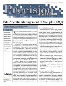
Sketch of soil percolation test setup/equipment:
Note: Percolation tests should be done at lease 10 feet from the location of any deep pit.
Equipment Needed Required: 1 2 3 4 3. 4. 5. 6. 7. 8.
Shovel or spade A watch with displays seconds or a stop watch to record time of percolation A flashlight to better see in the hole to make the timing more accurate About 2 cubic feet of washed gravel or crushed stone for the bottom of the hole 1 hardwood piece of lath 3-4 feet long for measuring stick 1- six inch piece of hardwood lath for cross piece 2- finishing nails to be set one inch apart to measure the time for one inch of water to percolate from the hole 2-4 screws or nails to nail the cross piece to the measuring stick about 15 gallons of water for percolation testing Form Oneida County Soil and Site Evaluation Data Entry Form or DOH-1327 to record the percolation test results
Procedure
(1)
Make sure proper construction safety practices are followed.
(2)
Dig a hole with vertical sides approximately 12 inches wide on all four sides or 12 inches in diameter. If an absorption field is being considered, the depth of the test holes should be 24 to 30 inches below final grade or at the projected bottom of trenches in shallower/deeper systems. If a seepage pit must be used, percolation tests should be conducted at one-half the depth and at the full estimated depth of the seepage pit. In order to facilitate conducting the test and preventing cave-in, a two-tiered excavation should be made approximately two feet above the bottom of the proposed seepage pit and two feet above the half-depth of the proposed seepage pit. Percolation test pits should be dug approximately two feet deep into each tier base. It is necessary to place washed aggregate in the lower two inches of each percolation test hole to reduce scouring and silting action when water is poured into the hole. T e sides of percolation holes should be scraped to avoid smearing. Figure 3 depicts a soil percolation test.
(3)
Pre-soak the test hole by periodically filling the hole with water and allowing the water to seep away. This procedure should be performed for at least four hours and should begin one day before the test, except in clean, coarse sand and gravel. After the water from the final pre-soaking has seeped away, remove any loose soil that has fallen from the sides of the hole.
(4)
Pour clean water into the hole, with as little splashing as possible, to a depth of six inches above the bottom of the test hole.
(5)
Observe and record the time in minutes required for the water to drop from the six inch depth to the five inch depth.
(6)
Repeat the test a minimum of three times until the time for the water to drop from six (6) inches to five (5) inches for two successive tests is approximately equal. The longest time interval to drop one inch shall be taken as the stabilized rate of percolation and shall serve as the basis of design for the absorption system.
For example, assume the following times were recorded while performing steps (d) thru (e) noted above: Run Number Time for One Inch Drop (Minutes) Run Number Minutes per inch 1. 24 2. 27 3. 30 4. 30 The stabilized percolation rate is 30 minutes per inch. Percolation rates, projected flow rates and observed boundary conditions coupled with Tables 4, 5 and 6 are frequently used to design needed absorptive facilities.