Software defined GPS receiver Friedt & al. Intro & basics User perspective
Software Defined Radio for processing GNSS signals
Dev perspective Got it ! What next ...
S. Martinez Gutierrez, J.-M Friedt, G. Cabodevila, P.Y Bourgeois, E. Rubiola FEMTO-ST Time & Frequency, Besan¸con, France
www.femto-st.fr
first-tf.com
Slides available at http://jmfriedt.free.fr/efts_gps.pdf January 31, 2015
1 / 36
Software defined GPS receiver Friedt & al. Intro & basics User perspective Dev perspective Got it ! What next ...
Introduction: GNSS GNSS: • Spaceborne atomic clocks 1 • Aim: use of ultrastable time references beyond positioning ... • ... eg. tide gauge 2 , moisture detection 3 , phase monitoring (TEC) • Requires at least phase recovery. • Educational purpose: detailed understanding of the steps needed to complete a GPS receiver low phase noise LO ! Use a low cost DVB-T receiver for acquisition: • 8 bit-resolution • poor sensitivity ⇒ pre-amplified antenna • 2.4 MHz measurement bandwidth limited by
USB bandwidth (I, Q components) • gnss-sdr /w GNURadio processing blocks 1 http://geodesie.ign.fr/journee-gnss-science/ 2 K.M. Larson: http://spot.colorado.edu/ kristine/Kristine_Larson/Home.html ~ 3 Bock et. al., West African Monsoon observed with ground-based GPS receivers ..., J. Geophysical Research 113, D21105 (2008), at http://onlinelibrary.wiley.com/doi/10.1029/2008JD010327/pdf
2 / 36
Software defined GPS receiver
Introduction: GPS basics
Friedt & al. Intro & basics User perspective Dev perspective Got it ! What next ...
Borre & al. p.18 3 / 36
Software defined GPS receiver
Objectives
Friedt & al. Intro & basics User perspective Dev perspective Got it ! What next ...
• a modulator generates the information, here encoded in the phase
of the carrier • the information is carried on a signal whose frequency varies (Doppler, thermal drift of LO) • recovering the transmitted information is a matter of eliminating carrier information • two degrees of freedom (carrier frequency and CDMA for satellite identification) will require two feedback loops to recover the information ⇒ carrier recovery and code position (delay) recovery 1575.42 MHz+/−df feedback loop NAV NAV (50 bps) PRN (1.023 Mbps)
PRN feedback loop 4 / 36
Software defined GPS receiver
SDR: user perspective
Friedt & al. Intro & basics User perspective Dev perspective Got it ! What next ...
• DVB-T dongle application : L1 C/A at 1.023 MHz barely meets the
Nyquist criteria when sampling at 2 MHz (no need to: strong assumption on modulation, i.e. 2/1.023=1.95 symbol/period) • Receiver sensitivity ?
Receiver E4000 R820T FC0013
137 MHz -105 -112 -112
434 MHz -105 -112 -111
1090 MHz -96 -109 -76
1500 MHz -95 -102 -58
Receiver E4000 R820T FC0013
137 MHz -109 -117 -116
434 MHz -110 -119 -115
1090 MHz -101 -113 -80
1500 MHz -101 -110 -62
Carrier power (dBm) needed for a demodulated signal SNR of 10 dB. All dongles set to their max gain (RF=39 dB and IF=45 dB for E4000, RF=50 dB for R820T, RF=20 dB for FC0013). Top: FM, bottom: AM. 5 / 36
Software defined GPS receiver Friedt & al. Intro & basics User perspective
Link budget: is it possible ? • Emitted power: 25.6 W=14 dBW
Dev perspective
• 13 dBi antenna gain
Got it !
• FSPL (21000 km)=182 dB
What next ...
• Received power=-155 dBW=-125dBm • Themal noise in a 2 MHz BW:
-174 dBm/Hz+10·log10 (2 MHz)=-111 dBm • Compression (coding) gain:
BW×τ =2 MHz×1 ms=33 dB • SNR=(−125 + 33) − (−111)=19 dB • Receiver antenna amplification: +27 dB
⇒ (-125+27)-(-102DVB−T ) '4 dB SNR R820T+RTL2832U based DVB-T receiver, bias T, antenna (30$)
4
4 http://www.adafruit.com/product/960: 13$ antenna and http://www.dx.com/p/ rtl2832u-r820t-mini-dvb-t-dab-fm-usb-digital-tv-dongle-black-170541: 12$ dongle 6 / 36
Software defined GPS receiver
SDR: user perspective
Friedt & al. Intro & basics
• Frequency offset budget: LO offset (±50 ppm) & drift
User perspective
What next ...
-55 offset frequence (ppm)
Got it !
(temperature) + remote carrier dependence with position in space • Identify carrier frequency mismatch: carrier recovery (phase) issue • Temperature dependence : front-end-cal 5 over > a week -56 -57 -58 -59 -60 -61 -62
0
50
100
150 200 temps (h)
250
300
0
50
100
150 200 temps (h)
250
300
30 temperature (degC)
Dev perspective
25 20 15 10 5
[......7...........19.......27.....] Total signal acquisition run time 11.703 [seconds] Reference Time: GPS Week: 790 GPS TOW: 209107 16728.560000 ~ UTC: Tue Oct 14 12:05:08 2014 Current TOW obtained from SUPL assistance = 209107 Reference location (defined in config file): 350 Latitude=47.3 [] Longitude=6 [] Altitude=10 [m] Doppler analysis results: SV ID Measured [Hz] Predicted [Hz] 7 92437.50 1848.25 19 94125.00 3080.82 27 93000.00 2116.75 Parameters estimation for Elonics E4000 Front-End: Sampling frequency =1999884.81 [Hz] IF bias present in baseband=90736.35 [Hz] Reference oscillator error =-57.60 [ppm] 350 Corrected Doppler vs. Predicted SV ID Corrected [Hz] Predicted [Hz] 7 1701.15 1848.25 19 3388.65 3080.82 27 2263.65 2116.75 GNSS-SDR Front-end calibration program ended.
PSK signal is hidden by phase rotation if incoming carrier and LO mismatch 5 gnss-sdr.org
7 / 36
Software defined GPS receiver
SDR: user perspective
Friedt & al. Intro & basics
Calculation of Doppler shift as a function of orbital parameters
User perspective Dev perspective Got it !
• Orbiting at 20000 km in 12 hours
What next ...
⇒ 2π(6400 + 20000)/12 = 13800 km/h=3840 m/s
v P
90−θ •
v θ
H’
H •
R R+r Earth
Receiver at position P observes the satellite from horizon to horizon HH 0 . At H, velocity vector ~ v along the satellite trajectory is projected towards P along ~ vk with ϑ meeting R the condition sin(ϑ) = R+r and hence |~ vk | = |~ v | · cos(90 − ϑ) = |~ v | · sin(ϑ) = |~ v | · R/(R + r ).
• Here
r orbit
|~ vk | = 13800·6400/(6400+20000) = 3345 km/h and the Doppler shift is ∆f = f0 · |~ vk |/c = ±4800 Hz' 3.1 ppm
8 / 36
Software defined GPS receiver
SDR: user perspective
Friedt & al. Intro & basics
Calculation of Doppler shift as a function of orbital parameters
User perspective
25
Dev perspective Got it !
• Orbiting at 20000 km in 12 hours ⇒ 2π(6400 + 20000)/12 = 13800 km/h=3840 m/s
20
What next ...
• Receiver at position P observes the
-4000
-2000
0
2000
Doppler shift (Hz)
4000
0
5
10
15 time (h)
satellite from horizon to horizon HH 0 .
• At H, velocity vector ~v along the satellite trajectory is projected towards P along ~ vk with ϑ meeting R the condition sin(ϑ) = R+r and hence |~ vk | = |~ v | · cos(90 − ϑ) = |~ v | · sin(ϑ) = |~ v | · R/(R + r ).
• Here |~ vk | = 13800·6400/(6400+20000) = 3345 km/h and the Doppler shift is ∆f = f0 · |~ vk |/c = ±4800 Hz' 3.1 ppm
9 / 36
Software defined GPS receiver Friedt & al.
SDR: developer perspective
Intro & basics
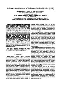
• Real life: LO offset introduces ∆ω and receiver mixer yields
cos(∆ω · t + ϕ): ϕ variation hidden in ∆ω · t Mixer acts as BPSK modulator 1
X
2
signal2 (u.a.)
0 −0.5 −1 0
1 0.8
0.5
0.6 0.4 0.2 0
500
1000 1500 temps (u.a.)
2000
0
500
1000 1500 temps (u.a.)
500 400 300 200
1000
modulation
100
cos(ϕ)2 ∝ cos(2ϕ) ϕ ∈ [0; π] ⇒ 2ϕ = 0 [2π]
0 800 850 900 950 1000 1050 1100 1150 1200 frequence(u.a.)
2000
FFT 800
porteuse
FFT
FFT(signal2) (u.a.)
What next ...
• Ideal recovery: mix with ω and cos(ϕ) is left
porteuse (absente)
Got it !
• Problem: BPSK modulates the carrier as ϕ = [0; π]: sin(ωt + ϕ)
signal (u.a.)
Dev perspective
FFT(signal) (u.a.)
User perspective
600 400 200 0 800 850 900 950 1000 1050 1100 1150 1200 frequence(u.a.)
Carrier recovery by squaring BPSK 10 / 36
Software defined GPS receiver Friedt & al. Intro & basics User perspective
SDR: developer perspective • Problem: BPSK modulates the carrier as ϕ = [0; π]: sin(ωt + ϕ)
Dev perspective
• Ideal recovery: mix with ω and cos(ϕ) is left
Got it !
• Real life: LO offset introduces ∆ω and receiver mixer yields
What next ...
cos(∆ω · t + ϕ): ϕ variation hidden in ∆ω · t emission
Mixer acts as BPSK modulator
reception
Source 1.21 GHz LO, −43 dBm IF
RF
BPSK
DVB−T
100 kHz modulated 1Vpp Mixer creates signal the BPSK modulation of the carrier at 1210 MHz
cos(ϕ)2 ∝ cos(2ϕ) ϕ ∈ [0; π] ⇒ 2ϕ = 0 [2π]
Practical BPSK signala , here ←− squared by oscilloscope software a
E. Rubiola, Tutorial on the double balanced mixer, http://arxiv.org/pdf/physics/0608211.pdf 11 / 36
Software defined GPS receiver Friedt & al.
SDR: developer perspective
Intro & basics User perspective Dev perspective
Software based carrier recovery (feedback loop not allowed in GNURadio): use the ready made Costas loop block
Got it ! What next ...
12 / 36
Software defined GPS receiver
SDR: developer perspective
Friedt & al. Intro & basics User perspective Dev perspective
Software based carrier recovery (feedback loop not allowed in GNURadio): use the ready made Costas loop block
Got it ! What next ... (3)
(4) centered on 0 Hz = locked loop
(3)
(4) not centered on 0 Hz = unlocked loop
phase of signal shifted by the carrier frequency
phase of the signal hidden by phase rotations du to freq. offset
frequency offset
(2)
30 dB
received signal: carrier shifted wrt 0 Hz modulation
carrier
Locked Costas loop
(1) squared signal = removes the modulation carrier ∆f 20 dB
(1)
(2) received signal: excessive carrier offset
modulation
carrier
Unocked Costas loop 13 / 36
Software defined GPS receiver
SDR: developer perspective
Friedt & al. Intro & basics User perspective
• Single carrier demodulation is not applicable as is to GPS: CDMA
Dev perspective
• All GPS satellites send over the same frequency (shifted by
Doppler): need for correction by the BPSK modulation before carrier recovery (but PRN requires carrier ?!)
Got it ! What next ...
• Mockup system with a 7-bit FLSR code generated by C. Fluhr
(EFTS labs) code 1, after Costas
code 2, after Costas
60
35
50
30
20
20
0
0
0 0
25 0
time (sample) code 2, before Costas 20
10
xcorr
10 5 5
100 200 300 400 500 600 700 800 time (sample) code 1, shifted by 1200
25
50
20
40
15 10
0 0
100 200 300 400 500 600 700 800 time (sample)
0
100 200 300 400 500 600 700 800 time (sample)
Before and after Costas
0
100 200 300 400 500 600 700 800 time (sample)
30 20
5
0
100 200 300 400 500 600 700 800 time (sample) code 2, shifted by 1600 (’perfect’)
60
xcorr
xcorr
xcorr
30 10
0
0 0
20 15
10 5
0 15
100 200 300 400 500 600 700 800 time (sample) code 1, shifted by 1120
15
15
5
25
0 20
20
100 200 300 400 500 600 700 800
time (sample) code 1, before Costas
100 200 300 400 500 600 700 800 time (sample) code 1, shifted by 1120
xcorr
100 200 300 400 500 600 700 800
xcorr
0
30
10 5
0
10 5
10 5
15
10
15 xcorr
xcorr
xcorr
30
code 2, shifted by 1050
20
15
40 xcorr
code 1, shifted by 1050
20
25
10
0
0 0
100 200 300 400 500 600 700 800 time (sample)
With frequency compensation 14 / 36
Software defined GPS receiver
From mock-up to actual GPS signals
Friedt & al. Intro & basics User perspective Dev perspective Got it ! What next ...
We have demonstrated that cross-correlating with the PRN will yield non-zero signal even if carrier offsets exist. → get familiar with GPS PRN code: a bit more complex (combination of two LFSR) → how resistant is GPS PRN code (10 bits) to carrier frequency offset ? → applicability to recorded DVB-T data ? I
DVB-T
|xcorr (s × LO), PRN)|
exp(jωt) × exp(jω 0 t) exp(−jωt) × exp(jω 0 t)
Q cos(ωt) × exp(jω 0 t)
NCOf ∈ C
PRN∈ R
when handling complex functions, −f 6= f since exp(jft) 6= exp(−jft) + no need for band pass filter (mixer output is a single frequency) 15 / 36
Software defined GPS receiver
10-bit PRN code resistance to carrier offet
Friedt & al. Intro & basics
250
PRN1,PRN1 PRN2,PRN1 PRN1,1.003*PRN1 PRN1,1.01*PRN1
User perspective 200
Dev perspective
1
150 xcorr (a.u.)
What next ...
more o f f ; c l o s e a l l ; c l e a r a l l set (0 , ” defaultaxesfontname ” , ” Helvetica ”)
3
100
5 7
50
9
0 0
500
1000 sample offset (no unit)
11 2000
1500
13
250
PRN1,PRN1 PRN2,PRN1 PRN1,1.003*PRN1 PRN1,1.01*PRN1
15
200
a=c a c o d e ( [ 1 : 3 1 ] , 1 ) ; a=a ’ ; a=a−mean ( a ) ; plot ( xcorr (a (: ,1) ,a (: ,1) ) , ’ r ’ ) h o l d on plot ( xcorr (a (: ,1) ,a (: ,2) ) ) x l a b e l ( ’ s a m p l e o f f s e t ( no u n i t ) ’ ) ylabel ( ’ xcorr (a . u .) ’ ) h o l d on a2=c a c o d e ( 1 , 1 . 0 0 3 ) ; a1=c a c o d e ( 1 , 1 ) ; p l o t ( x c o r r ( a1−mean ( a1 ) , a2−mean ( a2 ) ) , ’ c ’ ) a2=c a c o d e ( 1 , 1 . 0 1 ) ; a1=c a c o d e ( 1 , 1 ) ; p l o t ( x c o r r ( a1−mean ( a1 ) , a2−mean ( a2 ) ) , ’ g ’ ) % 10 kHz /1023 kHz =0.01
150 xcorr (a.u.)
Got it !
cacode.m available at Matlab Centrala
100
a
50
K.S. Raju & al., Digital GPS Signal Generator for L1 Band, Signal & Image Processing: An International Journal (SIPIJ) 3 (6), Dec. 2012, available at http://airccse.org/journal/sipij/papers/3612sipij07.pdf
0 1000
1020
1040 1060 sample offset (no unit)
1080
1100
16 / 36
Software defined GPS receiver
Application to real GPS signals
Friedt & al. Intro & basics User perspective Dev perspective Got it ! What next ...
• gnss-sdr provides a calibration software that stores the recorded
samples (2 MS/s) in a temporary file • when calibrating the dongle, we have saved the result of the gnss-sdr calibration process and the raw sample • we now process these datasets and compare our analysis with those
of gnss-sdr 2 4 6 8 10 12 14
x=r e a d c o m p l e x b i n a r y ( ’ 1413968929 c a p t u r e . d a t ’ ) ; t i m e = [ 0 : 1 / 2 e6 : l e n g t h ( x ) /2 e6 ] ’ ; t i m e=t i m e ( 1 : end −1) ; f o r m=1:37 a=c a c o d e (m, 2 / 1 . 0 2 3 ) ; a=a−mean ( a ) ; l =1; m % d i s p l a y s a t PRN f o r f r e q =8e4 : 2 0 0 : 1 e5 % r u n t h r o u g h p o s s i b l e f r e q u e n c y o f f s e t s : c f f r o n t−end−c a l m y s i n e=e x p ( j ∗2∗ p i∗(− f r e q )∗t i m e ) ; % LO xx=x .∗ m y s i n e ; % frequency s h i f t the s i g n a l [ u ( l ,m) , v ( l ,m) ]=max ( a b s ( x c o r r ( a , xx ) ) ) ; % c h e c k f o r c r o s s c o r r e l a t i o n max . l=l +1; end end figure imagesc ( abs ( u ) )
Notice the extended frequency offset range: hi accuracy LO will speed up acquisition time 17 / 36
Software defined GPS receiver
Application to real GPS signals
Friedt & al. Intro & basics User perspective Dev perspective
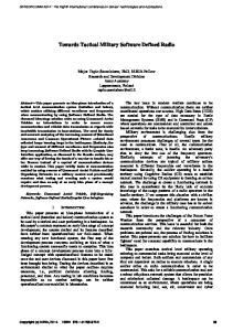
2D plot with PRN number as X-axis and frequency offset in Y-axis
Got it ! 0
What next ... 50
100
freq offset
150
200
250
300
350
400 5
10
15
20 PRN
25
30
35
Borre & al. p.23: sat ID = PRN, here 4, 7, 11, 15, 19, 27, 30
Latitude=47.3 [] Longitude=6 [] Altitude=10 [m] Doppler analysis results: SV ID Measured [Hz] Predicted [Hz] 4 93875.00 3547.36 7 88625.00 -1439.45 11 93625.00 3455.35 15 89437.50 -694.02 19 92000.00 1783.79 27 90250.00 96.13 30 90375.00 139.85 Parameters estimation for Elonics E4000 Front-End: Sampling frequency =1999885.64 [Hz] IF bias present in baseband=90082.96 [Hz] Reference oscillator error =-57.18 [ppm] Corrected Doppler vs. Predicted SV ID Corrected [Hz] Predicted [Hz] 4 3792.04 3547.36 7 -1457.96 -1439.45 11 3542.04 3455.35 15 -645.46 -694.02 19 1917.04 1783.79 27 167.04 96.13 30 292.04 139.85 GNSS-SDR Front-end calibration program ended.
18 / 36
Software defined GPS receiver
Application to real GPS signals
Friedt & al. Intro & basics User perspective Dev perspective
2D plot with PRN number as X-axis and frequency offset in Y-axis
Got it ! What next ...
0
50
frequency shift (200 Hz/point)
100
150
200
250
300
350
400 5
10
15
20 PRN
sat ID = PRN, here 19, 27
25
30
35
[......7...........19.......27.....] Total signal acquisition run time 11.4224 [seconds] Reference Time: GPS Week: 791 GPS TOW: 299342 23947.360000 ~ UTC: Wed Oct 22 13:09:03 2014 Current TOW obtained from SUPL assistance = 299343 Reference location (defined in config file): Latitude=47.3 [] Longitude=6 [] Altitude=10 [m] Doppler analysis results: SV ID Measured [Hz] Predicted [Hz] 7 88687.50 -1596.95 19 92000.00 1664.98 27 90250.00 -55.40 Parameters estimation for Elonics E4000 Front-End: Sampling frequency =1999885.48 [Hz] IF bias present in baseband=90205.75 [Hz] Reference oscillator error =-57.26 [ppm] Corrected Doppler vs. Predicted SV ID Corrected [Hz] Predicted [Hz] 7 -1518.25 -1596.95 19 1794.25 1664.98 27 44.25 -55.40 GNSS-SDR Front-end calibration program ended.
19 / 36
Software defined GPS receiver
Application to real GPS signals
Friedt & al. Intro & basics User perspective Dev perspective
2D plot with PRN number as X-axis and frequency offset in Y-axis
Got it ! What next ...
0
50
100
freq offset
150
200
250
300
350
400 5
10
15
20 PRN
ID = PRN, here 7, 11, 19, 27, 30
25
30
35
GPS TOW: 299662 23972.960000 ~ UTC: Wed Oct 22 13:14:23 2014 Current TOW obtained from SUPL assistance = 299662 Reference location (defined in config file): Latitude=47.3 [] Longitude=6 [] Altitude=10 [m] Doppler analysis results: SV ID Measured [Hz] Predicted [Hz] 7 89250.00 -1745.40 11 93875.00 3382.16 19 91625.00 1541.05 27 90000.00 -209.33 30 90000.00 -244.43 Parameters estimation for Elonics E4000 Front-End: Sampling frequency =1999885.36 [Hz] IF bias present in baseband=90302.65 [Hz] Reference oscillator error =-57.32 [ppm] Corrected Doppler vs. Predicted SV ID Corrected [Hz] Predicted [Hz] 7 -1052.65 -1745.40 11 3572.35 3382.16 19 1322.35 1541.05 27 -302.65 -209.33 30 -302.65 -244.43 GNSS-SDR Front-end calibration program ended.
sat
20 / 36
Software defined GPS receiver
Did we get this right ? Nav. messages
Friedt & al. Intro & basics User perspective Dev perspective
• Navigation message is XORed with C/A
Got it !
• 50 bps or 20 ms ⇒ longer record than front-end-cal
What next ...
• C/A PRN repeats every 1023 cycles at 1.023 MHz ⇒ probe
correlation phase every 1 ms 25
80000
PRN 31
20
cross correlation
frequency offset (Hz)
85000
90000
15
10
95000
5
100000 5
10
15 20 PRN number (no unit)
25
30
35
0 90000
92000
94000 96000 frequency offset
98000
100000
PRN 31: visibility chart & cross-correlation for carrier freq. identification 21 / 36
Software defined GPS receiver
Did we get this right ? Nav. messages
Friedt & al. Intro & basics User perspective Dev perspective
• Navigation message is XORed with C/A
Got it !
• 50 bps or 20 ms ⇒ longer record than front-end-cal
What next ...
• C/A PRN repeats every 1023 cycles at 1.023 MHz ⇒ probe
correlation phase every 1 ms 40
40
FFT freq estimate manual correction: +100 Hz unwrapped manual corr.
0
0 phase (rad)
20
phase (rad)
20
FFT freq estimate manual correction: +100 Hz unwrapped manual corr.
-20
-20
-40
-40
-60 0
500
1000
1500
2000 time (ms)
2500
3000
3500
4000
-60 2500
2550
2600 time (ms)
2650
2700
Manual frequency correction to get a flat phase in each bit (+100 Hz) Nav signal: bit recovery requires phase tracking (here lin. fit removal) ! 22 / 36
Software defined GPS receiver
Feedback loop: carrier frequency tracking
Friedt & al. Intro & basics User perspective Dev perspective
• Need for frequency tracking to compensate for Doppler shift and
Got it !
temperature drift • Need for PRN phase positioning (?)
What next ...
DVB−T 2 MS/s 8 bits A/DC
atan(Q/I)
PRN
PRN
PRN position
frequency tracking
Quick reminder on implementing a feedback loop control: a·z+b a+b·z −1 C (z) = O(z) I (z) = c·z+d = c+d·z −1 ⇒ c · Ok + d · Ok−1 = a · Ik + b · Ik−1 or Ok = a/c · Ik + b/c · Ik−1 − d/c · Ok−1 23 / 36
Software defined GPS receiver
Phase discriminator
Friedt & al. Intro & basics User perspective Dev perspective Got it !
• The phase is needed for carrier frequency tracking yet encodes the
BPSK information ⇒ discriminator insensitive to 180o phase shifts • Keep the phase close to 0 means arctan(Q/I ) ' 0 ⇒ Q ' 0
What next ...
• arctan(Q/I ) is the exact phase estimate insensitive to 180o rotations • atan2(Q, I ) provides the full phase including 180o rotations ⇒
needed to exctract the navigation message • Q × sign(I ) is easier to compute and yields the same functionality6 . Q (1,1)=(−1,−1)
Following graphs: from top to bottom the phase of the cross correlation maximum, the NCO frequency, and the extracted navigation bits.
I (−1,1)=(1,−1)
6 C.
O’Driscoll, M.G. Petovello & G. Lachapelle, Choosing the coherent integration time for Kalman filter-based carrier-phase tracking of GNSS signals, GPS Solut 15 345–356 (2011) 24 / 36
Software defined GPS receiver
Feedback loop: carrier frequency tracking
Friedt & al. Intro & basics
sampling rate: 2.0 MS/s finit = 92960 Hz
Discriminator: arctan(Q/I ) finit = 92860 Hz
2
2
phase [pi], rad)
5
[ num , den ]= t f d a t a ( Cz , ’ v ’ ) ; m y s i n e=e x p ( j ∗(2∗ p i ∗mod ( ( ( f r e q 0+ f r ( l ) )∗t i m e ( kk : kk+f s ∗1000−1) ) , 1 ) ) ) ; xx=x ( kk : kk+f s ∗1000−1) .∗ m y s i n e ; zp=x c o r r ( ap , xx ,MAXLAG) ; % we h a v e d e f i n e d MAXLAG=2000 yp ( l )=a t a n ( imag ( zp ( k ( l ) ) ) . / r e a l ( zp ( k ( l ) ) ) ) ; % discriminator f r e q=−den ( 2 )∗freqm1−den ( 3 )∗f r e q m 2+num ( 1 )∗yp ( l )+num ( 2 )∗ym ; % f e e d b a c k l o o p
1 0 −1 −2
0
500
1000
1500
2000
2500
3000
3500
4000
1 0 −1 −2
4500
0
500
1000
1500
2000
2500
3000
3500
4000
4500
500
1000
1500
2000
2500
3000
3500
4000
4500
500
1000
1500
2000 2500 time (ms)
3000
3500
4000
4500
0
10 freq. (Hz)
3
−50
0 −10 −20
−100 500
1000
1500
2000
2500
3000
3500
4000
4500
6
6 phase (bpsk)
1
What next ...
phase [pi], rad)
Got it !
Te=1e-3;A=150;Cz=tf((1/A)*[2-a -1],[1 -2 1],Te);
freq. (Hz)
Dev perspective
phase (bpsk)
User perspective
4 2 0 −2
0
500
1000
1500
2000 2500 time (ms)
3000
3500
4000
4500
4 2 0 −2
0
25 / 36
Software defined GPS receiver
Feedback loop: carrier frequency tracking
Friedt & al. Intro & basics User perspective Dev perspective
• Difficulty in carrier tracking due to low sampling rate ?
Got it ! What next ...
• Attempt at 2.4 MS/s 2 phase [pi], rad)
phase [pi], rad)
2 1 0 −1 −2
0
500
1000
1500
2000
2500
3000
3500
4000
0 −1 −2
4500
0
0
500
1000
1500
2000
2500
3000
3500
4000
4500
500
1000
1500
2000
2500
3000
3500
4000
4500
500
1000
1500
2000 2500 time (ms)
3000
3500
4000
4500
20 −2
freq. (Hz)
freq. (Hz)
1
−4 −6
15 10 5 0
500
1000
1500
2000
2500
3000
3500
4000
4500 6 phase (bpsk)
phase (bpsk)
6 4 2 0 −2
0
500
1000
1500
2000 2500 time (ms)
3000
3500
4000
4500
4 2 0 −2
0
⇒ Much poorer results ! (sampling rate mismatch ?) 26 / 36
Software defined GPS receiver
Feedback loop: carrier frequency tracking
Friedt & al. Intro & basics User perspective Dev perspective Got it !
9-second long decoding without divergence, after implementing PRN code positioning (R&S SMA100)
What next ... atan (rad)
2 1 0 −1 −2
0
1000
2000
3000
4000 5000 time (ms)
6000
7000
8000
9000
0
1000
2000
3000
4000 5000 time (ms)
6000
7000
8000
9000
0
1000
2000
3000
4000 5000 time (ms)
6000
7000
8000
9000
freq (Hz)
6 4 2 0 −2
angle (rad)
6 4 2 0 −2
27 / 36
Software defined GPS receiver
(Temporary) conclusions – perspectives
Friedt & al. Intro & basics User perspective Dev perspective Got it ! What next ...
Conclusion ... • Rather good understanding of the modulation scheme • Operational carrier recovery even in a CDMA environment • The so-called GPS acquisition is functional • Tracking loop functional but VERY sensitive
... and perspectives: • if interested, could provide navigation information (to be
demonstrated – 50 Hz, output of the correlation scheme) • postprocessing → real time processing with gnss-sdr ... • ... whose code remains to be understood ! • Beyond DVB-T: L2 tracking ? L5 tracking ?
7
• Passive RADAR: use remote emitter for Doppler-distance mapping 7 http://pmonta.com/blog/2014/07/08/gps-p-code-exploration/ 28 / 36
Software defined GPS receiver Friedt & al. Intro & basics User perspective
Software defined radio: secondary correlator peaks
Dev perspective Got it ! What next ...
• Access to raw correlator output ⇒ search for multipath signal • Cross correlation of direct and reflected signal ⇒ even compatible
with P-code • Water height measurement performed by amplitude measurement or
phase measurement
8
• SNR hints at surface structure • opportunistic signal source: extension to passive RADAR analysis • Replace the known C/A pseudorandom code with any information transmitted • PRN v.s Doppler is now replaced with time-delay v.s Doppler (Doppler helping to get rid of clutter) • common clock on reference and measurement receivers to get rid of relative oscillator drift 8 trs-new.jpl.nasa.gov/dspace/bitstream/2014/14430/1/00-0867.pdf or http://arxiv.org/pdf/physics/0212055.pdf 29 / 36
Software defined GPS receiver
Experimental setup
Friedt & al. Intro & basics User perspective Dev perspective Got it !
PRN v.s Doppler is now replaced with phase shift (delay=distance) v.s Doppler (speed)
What next ...
• Common clock to both
dongles (either external or from one of the quartz) • Simultaneous acquisition from
both dongles • No apparent effect of USB bus
(load due to file transfer does not induce phase slip) • Ability to detect phase but
slow signal drift ?! dependent on how the dongles are initialized ?
30 / 36
Software defined GPS receiver
Experimental setup
Friedt & al. Intro & basics User perspective Dev perspective Got it !
PRN v.s Doppler is now replaced with phase shift (delay=distance) v.s Doppler (speed)
What next ...
• Common clock to both
dongles (either external or from one of the quartz) • Simultaneous acquisition from
both dongles • No apparent effect of USB bus
(load due to file transfer does not induce phase slip) • Ability to detect phase but
slow signal drift ?! dependent on how the dongles are initialized ?
31 / 36
Software defined GPS receiver
Experimental setup
Friedt & al. Intro & basics User perspective Dev perspective Got it !
PRN v.s Doppler is now replaced with phase shift (delay=distance) v.s Doppler (speed)
What next ...
• Common clock to both
dongles (either external or from one of the quartz) • Simultaneous acquisition from
both dongles • No apparent effect of USB bus
(load due to file transfer does not induce phase slip) • Ability to detect phase but
slow signal drift ?! dependent Example on commercial FM broadcast on how the dongles are initialized ?
32 / 36
Software defined GPS receiver
Perspectives
Friedt & al. Intro & basics User perspective Dev perspective Got it ! What next ...
• Stabilize understanding of carrier frequency feedback loop • Demonstrate phase shift when antenna is moved (carrier phase
tracking, λ = 300/1575 ' 19 cm • Use carrier phase information in local oscillator stabilization feedback loop Replace E4k with R820T • so far, no GPS signal decoded from a R820T based receiver From educational to research analysis • replace DVB-T with high-bandwidth multichannel acquisition card EGNOS (European WAAS 9 ) decoding ? • L1-compatible signal sent by geosynchronous satellites • extended PRN codes beyond 37: • 135, 138: over USA • 120, 124 (decomissioned), 126, 136: active over Europe
• new PRN code generator seems functional (≤31) but no EGNOS
signal detected 9 Wide
Area Augmented System 33 / 36
Software defined GPS receiver
References
Friedt & al. Intro & basics
1
User perspective Dev perspective Got it !
2
What next ...
3 4
5 6
7
K. Borre et al., A Software-Defined GPS and Galileo Receiver – A Single-Frequency Approach, Birkh¨auser Boston, 2007 E.D Kaplan, Understanding GPS: Principles and Applications, 2nd Ed., Artech House (2005) gnss-sdr.org, significantly http://gnss-sdr.org/node/50 C. Fern´andez-Prades et al., GNSS-SDR: an open source tool for researchers and developers, Proc. ION GNSS Conference 2011 10 Michele’s GNSS blog at http://michelebavaro.blogspot.fr/ SoftGPS web page kom.aau.dk/project/softgps, now moved to the rather useless gfix.dk/matlab-gnss-sdr-book P. Boven, Hacking the GPS, OHM2013 program at https://program.ohm2013.org/event/314.html, unfortunately no trace other than notes and memories
Archive of data and scripts: http://jmfriedt.free/fr/efts_archive.tar.gz in addition to the slides at http://jmfriedt.free/fr/efts_slides.pdf 10 http://www.cttc.es/publication/ gnss-sdr-an-open-source-tool-for-researchers-and-developers/ 34 / 36
Software defined GPS receiver Friedt & al. Intro & basics User perspective Dev perspective Got it !
What about this squared carrier story ? P. Boven at OHM2013: track GPS by squaring the received signal to concentrate the spread spectrum into a single frequency bin ...
What next ...
35 / 36
Software defined GPS receiver Friedt & al. Intro & basics User perspective Dev perspective Got it !
What about this squared carrier story ? ... but the de-spread GPS signal is narrowband (±5 kHz) and hidden in the broadband noise + LO offset
What next ...
Knowing what to look for, we found it ! 36 / 36