International Journal of Emerging Technology and Advanced Engineering Website: www.ijetae.com (ISSN 2250-2459, ISO 9001:2008 Certified Journal, Volume 4, Issue 3, March 2014)
Simulation and Static Analysis on Improved Design of Excavator Boom Shiva Soni¹, S. L. Ahirwar², Reliance Jain³, Ashish Kumar Shrivastava⁴ 1
M.Tech. Scholar, Oriental Institute of Science and Technology, Bhopal, M.P., India. 2,3,4 A.P. Department of Mechanical Engineering, OIST, Bhopal, M.P., India. The excavation of this task is usually performed by a human operator who controls the motion of the machine manually by using the visual feedback provided through his or her own eyes [4].Typical hydraulic backhoe excavator linkages are shown in Figure 1. It consists of link members: the bucket, the stick, the boom and the revolving superstructure (upper carriage). On the other hand, the work functions of the backhoe often overlap those of other machines such as front-end loaders, tractor shovel, scrapers, clamshells and draglines in addition, it is particularly useful for trenching foundation footing excavation, basement excavation and similar works [2, 1]. Normally backhoe excavators are working under worst working conditions. Due to severe working conditions, excavator parts are subjected to high loads and must work reliably under unpredictable working conditions. Thus, it is necessary for the designers to provide not only an equipment of maximum reliability but also of minimum weight and cost, keeping design safe under all loading conditions. The force analysis and strength analysis is important steps in the design of excavator parts. Figure 1 shows the typical hydraulic excavator linkages.
Abstract-- An excavator is a typical hydraulic heavy-duty human-operated machine used in general versatile construction operations, such as digging, ground leveling, carrying loads, dumping loads and straight traction. Normally backhoe excavators are working under worst working conditions. Due to severe working conditions, excavator parts are subjected to high loads and must work reliably under unpredictable working conditions. The objective of this paper is to analyze the existing design and redesign the excavator boom which is suitable for side digging and also for digging over hanged part of wall. Modeling of excavator attachment like boom, long arm, small arm, cylinder, bucket & coupling is done by using INVENTOR software. Model is exported through IGES file format for MESHING in Altair Hypermesh Analysis Software. Meshing is done using suitable type of elements. Material property is assigned; Boundary conditions and the forces are applied. Static analysis is done in INVERTOR software which is being supported by ANSYS software. During operation of excavator at different positions the stresses induced in the attachments varies. The forces applied in the analysis were calculated by using INVENTOR software, and reported that the Arm, Boom and Bucket shows stress in the attachment are coming under allowable limit. For reducing stresses and for optimum weight of the excavator parts, thickness of the material is reduced in the modeling. Keyword-- Rotary excavator boom, bucket, INVENTOR software.
I. INTRODUCTION Applications for backhoe excavator in India include use as a utility machine at large construction sites and urban infrastructure projects as well as the loading of hoppers and trucks, trenching, the cleaning of canals and ditches, general excavation, solid waste management and even demolition and mining work [7]. The useful task of backhoe hydraulic excavator is to free and/or remove surface materials such as soil from its original location and transfer it to another location by lowering the bucket, digging, pushing and/or pulling soil then lifting, swinging and emptying the bucket. Fig: 1 typical hydraulic backhoe excavator linkages
49
International Journal of Emerging Technology and Advanced Engineering Website: www.ijetae.com (ISSN 2250-2459, ISO 9001:2008 Certified Journal, Volume 4, Issue 3, March 2014) II. METHODOLOGY Model Building INVENTOR software is used for building 3D geometric models of the frame, working arms, bucket rods and bucket, bases on drawings of the excavator. INVENTION model is prepared using dimension given in Figure 2 & model refer by Figure 2.1. Figure 2.2 shows the geometric model of a mechanism assembled from the above components.
Figure: 2.2 Model Prepared by above dimension
Material The backhoe excavator working device parts are made up of different materials which are listed in table 1. For the fabrication of Excavator boom, welding provides higher strength. This change lightens the components of the arm, allows to increase the load capacity of the bucket and so it is possible to increase the excavator productivity per hour [5, 6]. Figure: 2 Dimensions of Excavator
Coupling A coupling is a device used to connect two shafts together at their ends for the purpose of transmitting power. Couplings do not normally allow disconnection of shafts during operation, however there are torque limiting couplings which can slip or disconnect when some torque limit is exceeded. The primary purpose of couplings is to join two pieces of rotating equipment while permitting some degree of misalignment or end movement or both. By careful selection, installation and maintenance of couplings, substantial savings can be made in reduced maintenance costs and downtime. Here as some of the key aspects on the constructional features of the Jaw type coupling. These points are to be considered for the proper selection of a coupling. - The metal hub is constructed of sintered iron, Galvanized Iron. The type of metal hub is mainly based on the area of operation of the coupling and its inertia aspects.
Figure: 2.1 Model of KOBELCO SK80MSR
50
International Journal of Emerging Technology and Advanced Engineering Website: www.ijetae.com (ISSN 2250-2459, ISO 9001:2008 Certified Journal, Volume 4, Issue 3, March 2014) - The spider is normally made up of a nonmetallic element like rubber, urethane, and hytrel because of their Elastomeric properties and in very rare cases bronze is used. Now let us look into the calculation aspects for the selection of jaw type couplings [8]
.
Steps for Selecting a Suitable Coupling for a Particular Application Step 1: Determine the Nominal Torque of your application by using the following formula: Nominal Torque = kW x 9550/r.pm at which the coupling is to run Step 2: Determine the application factor - The application area of the coupling is used to determine the application factor. These factors can vary from manufacturer to manufacture based on the methodology of design, material used etc. Step 3: Determine the design Torque: - The design torque is calculated using the following formula: Design Torque = Application factor x Nominal Torque Step 4: Selecting the Spider material: - The spider material needs to be selected based on the application for which it is to be used. Step 5: Selecting the coupling based on the above calculated and application factor values: - The coupling is selected based on the design torque for the appropriate spider type, completing the selection of a jaw type coupling. This is the basic methodology used for the selection of couplings [8]. A 4 Jaw coupling as shown in figure 3 and 3.1 has two flanges. One flange has a pin hole of required number at pitch circle diameter. The other flange will have a number of pins projected outside at pitch circle diameter to accommodate into the first flange holes with rubber bush. The driver and driven shafts are connected to their respective flanges i.e. output and input flanges by means of parallel square key. Mild-steel is considered for the input and output shafts, pins and keys. Over these pins, a circular natural rubber bush is provided and its length is equal to the length of the hole. The diameter of the flange holes is equal to the diameter of pin plus the thickness of rubber bush [10]. Now we can rotate the boom of excavator at 180 degree by using four jaw coupling followed by above 5 steps. Table 1 shows the material properties of coupling.
Figure: 3 Different parts of 4-jaw coupling
Figure: 3.1 Model of 4-jaw coupling
Load Conditions For the purpose of increasing the productivity of excavator, many different load conditions have been studied numerically on the original excavator in order to estimate a safety factor and the deformability or flexibility of each component. These parameters have been used in order to design a new arm. Two different load conditions have been checked in order to establish the stress conditions in each component of the excavator arm and bucket.
51
International Journal of Emerging Technology and Advanced Engineering Website: www.ijetae.com (ISSN 2250-2459, ISO 9001:2008 Certified Journal, Volume 4, Issue 3, March 2014) Figure 4 shows the first load condition with coupled boom concern with leveling operation which allows starting the bucket at the maximum and minimum distance from the axle of rotation. The distance of the bucket from the surface does not change in this roto-translation. The static force analysis is carried out on excavator bucket in two different loading conditions as shown in figure 4 & 5.
Figure: 5 second load condition
III.
D IGGING FORCE
Required digging force for excavator attachment is 7626N, which is enough and more than resistive forces offered by ground 3916N, for light duty construction work, which requires less pressure and power to actuate the backhoe mechanism for digging task at any position and fuel consumption is less, ultimately the operating cost gets reduced [2]. For proposed excavator attachment the digging force offered by bucket is 52.9 KN according to company (PRYOR PLANT HIAR).
Figure: 4 first load condition
The second load condition as shown in figure 5 with coupled boom concerns the lifting operation with the maximum load at the minimum distance from the axle of rotation. The second load condition examined is an exceptional condition. In this case the force applied to excavator arm including bucket is the maximum force generated by the hydraulic cylinders.
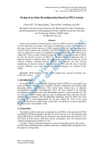
IV. MESHING IN EXCAVATOR ATTACHMENT Meshing is done by using Altair Hypermesh software, only for checking the reliability of excavator boom. There are total 399199 2D elements on proposed excavator attachment. Figure 6 shows the meshing on 4-jaw coupling of excavator boom and arm.
52
International Journal of Emerging Technology and Advanced Engineering Website: www.ijetae.com (ISSN 2250-2459, ISO 9001:2008 Certified Journal, Volume 4, Issue 3, March 2014) Table I Value of displacement in different zone
ZONE
VALUE IN MM
RED
0.4908
YELLOW
0.3926
PARRET GREEN
0.2945
GREEN
0.1963
SKY BLUE
0.0932
BLUE
0
Figure 7.1 shows the Von Mises Stresses which are under allowable condition and table II shows the value of Von Mises stresses in different zone. Fig. 6 Meshing on 4-jaw coupling and boom
V.
S IMULATION
Simulation of redesigned excavator boom is done using Autodesk Inventor designing software. Autodesk inventor 3D CAD software has an easy-to-use set of tools for 3-D mechanical design, documentation, and product simulation. The figure 4 shows the value of the applied load 200 Kg which is acting on the bucket. The static force analysis is carried out on excavator bucket in two different loading conditions as shown in figure 4 & 5. Figure 7 shows the Maximum displacement in the X plane of the excavator attachment may be 0.4908 mm. Lower part of the bucket is closer to the maximum value, this is due to unsupported part of the excavator.. Figure 7 shows the maximum displacement and table I show the value of displacement in different zone. Figure 7.1 Von Mises Stress at maximum load Table: II Value of Von Mises stresses in different zone
. Figure: 7 Maximum & Minimum Displacement
53
ZONE
VALUE IN MPa
RED
20.93
YELLOW
16.75
PARRET GREEN
12.56
GREEN
9.37
SKY BLUE
4.19
BLUE
0
International Journal of Emerging Technology and Advanced Engineering Website: www.ijetae.com (ISSN 2250-2459, ISO 9001:2008 Certified Journal, Volume 4, Issue 3, March 2014) Table: VIII Pin Constraint 3
VI. OPERATING CONDITION RESULTS Table: III Force 1
Load Type
Force
Magnitude
1500.000 N
Vector X
-79.363 N
Vector y
1497.899 N
Constraint Type
Pin Constraint
Fixed Radial Direction
Yes
Fixed Axial Direction
Yes
Fixed Tangential Direction
Yes
VII. RESULT SUMMARY Table: IV Bearing Load 1
Load Type
Bearing Load
Magnitude
100.000 N
Vector X
-0.000 N
Vector y
0.000 N
Vector Z
-100.000 N
Table X shows the analysis result for the redesigned Excavator attachment in which all forces , stresses and displacements are in allowable limit. Table: X Result Analysis Report
Name Volume
Table: V Bearing Load 2
Load Type
Bearing Load
Magnitude
100.000 N
Vector X
0.000 N
Vector y
0.000 N
Vector Z
100.000 N
Constraint Type
Pin Constraint
Fixed Radial Direction
Yes
Fixed Axial Direction Fixed Tangential Direction
Yes Yes
Table: VII Pin Constraint 2
Constraint Type
Pin Constraint
Fixed Radial Direction
Yes
Fixed Axial Direction
Yes
Fixed Tangential Direction
Yes
Mass Von Mises Stress 1st Principal Stress 3rd Principal Stress
375.942 kg
Displacement
0 mm 9.55481
Safety Factor X Displacement Y Displacement Z Displacement Equivalent Stain 1st Principal Strain 3rd Principal Strain
Table: VI Pin Constraint 1
54
Minimum 51250700 mm³
0.00000296753 Mpa -5.75645 Mpa -20.4148 Mpa
-0.116832 mm -0.0179311 mm -0.037573 mm 0.0000000000155843 -0.00000640714 -0.000195275
Maximum
20.9319 Mpa 22.7725 Mpa 5.58948 Mpa 0.489842 mm 15 0.249105 mm 0.475459 mm 0.0684823 mm 0.000209493 0.000238116 1.11419E-06
International Journal of Emerging Technology and Advanced Engineering Website: www.ijetae.com (ISSN 2250-2459, ISO 9001:2008 Certified Journal, Volume 4, Issue 3, March 2014) VIII. CONCLUSION
REFERENCES [1]
Shahram Tafazoli, Peter D. Lawrence, and S. E. Salcudean, ‘Identification of Inertial and Friction Parameters for Excavator Arms’, IEEE Transactions on Robotics & Automation, Vol. 15, No. 5, October 1999. [2] Yahya H. Zweiri, Lakmal D. Seneviratne and Kaspar Althoefer, ‘A Generalized Newton Method for Identification of Closed-chain Excavator Arm Parameters’, Proceedings of the 2003 IEEE lnlernstional Conference on Robotics & Automation Taipei, Taiwan, September 14-19, 2003. [3] D. Seward, C. Pacea, R. Morreyb, I. Sommervilleb, Reliability Engineering and System Safety 70, 15 March 2005 PP, 29–39 [4] Off Highway Research, Equipment Analysis, India Backhoe Loader, March 2008, PP.2 [5] Luigi Solazzi, ‘Design of aluminium boom and arm for an excavator’, Journal of Terramechanics 47 (2010) 201–207 [6] Srdan M. Bosˇnjak, ‘Comments on ‘‘Design of aluminium boom and arm for an excavator”, Journal of Terramechanics 48 (2011) 459–462. [7] B. P. Patel, J. M. Prajapati, Machine Design, Vol.4(2012) No.1, ISSN 1821-1259, PP. 59-66 [8] Sanjiv Kumar et.al., International Journal of Science and Technology, Vol. 1, No. 11, November 2012, ISSN 2049-7318, PP 602-608. [9] Bhaveshkumar P. Patel, Jagdish M. Prajapati, Machine Design, Vol.5 (2013) No.1, ISSN 1821-1259, PP 43-56. [10] http://www.brighthubengineering.com/machine-design/57174types-of-flexible-coupling-jaw-type-elastomericcoupling/#imgn_3.
The existence of commercial software packages has allowed engineers and analysts to narrow the development process in either products or systems since the past few decades. Virtual engineering and INVENTOR software provides detailed analysis of a conceptual design. These tools allow us to determine forces and stresses that are developed in critical points This helps us to determine modifications for the purpose of meeting the established criterion of the design. The study builds a complete, integrated and refined 3D INVENTOR model of the mechanism, and examines stresses and deformation at typical operating conditions. Static analysis is done in INVERTOR software which is being supported by ANSYS software. It improves design of the current product, and provides a new approach for design and analysis of similar products. Thus, the study aims at increasing the degree of freedom of boom and bucket for side digging & over hanged part digging, after considering different load Conditions and this can be achieved by introducing 4-jaw coupling for rotation of the boom and arm. So it will increase the safety of human being and loading vehicle’s sheet which is generally damaged by emptying the bucket.
55