SECTION 41 – STEERING – CHAPTER 1
1
SECTION 41 – STEERING Chapter 1 – Hydrostatic Steering System CONTENT Section
Description
41 000
Specifications . . . . . . . . . . . . . . . . . . . . . . . . . . . . . . . . . . . . . . . . . . . . . . . . . . . . . . . . . . . . . . . . 2 Tightening Torques . . . . . . . . . . . . . . . . . . . . . . . . . . . . . . . . . . . . . . . . . . . . . . . . . . . . . . . . . . . . 3 Special Tools . . . . . . . . . . . . . . . . . . . . . . . . . . . . . . . . . . . . . . . . . . . . . . . . . . . . . . . . . . . . . . . . . 3 Description and Operation . . . . . . . . . . . . . . . . . . . . . . . . . . . . . . . . . . . . . . . . . . . . . . . . . . . . . . 4 Fault Finding . . . . . . . . . . . . . . . . . . . . . . . . . . . . . . . . . . . . . . . . . . . . . . . . . . . . . . . . . . . . . . . . . 11 System Testing . . . . . . . . . . . . . . . . . . . . . . . . . . . . . . . . . . . . . . . . . . . . . . . . . . . . . . . . . . . . . . 12 Steering Motor – Removal and Installation . . . . . . . . . . . . . . . . . . . . . . . . . . . . . . . . . . . . . . . 14 Steering Motor Overhaul . . . . . . . . . . . . . . . . . . . . . . . . . . . . . . . . . . . . . . . . . . . . . . . . . . . . . . 16 Steering Column – Removal and installation . . . . . . . . . . . . . . . . . . . . . . . . . . . . . . . . . . . . . 24 Two Wheel Drive Steering Cylinder – Removal and Installation . . . . . . . . . . . . . . . . . . . . 26 Two Wheel Drive Steering Cylinder – Overhaul . . . . . . . . . . . . . . . . . . . . . . . . . . . . . . . . . . . 27 Four Wheel Drive Steering Cylinder – Removal and Installation . . . . . . . . . . . . . . . . . . . . 28 Four Wheel Drive Steering Cylinder – Overhaul . . . . . . . . . . . . . . . . . . . . . . . . . . . . . . . . . . 29
41 204
41 216
Page
604.55.111.00 – 06 – 2002
2
SECTION 41 – STEERING – CHAPTER 1 41 000 SPECIFICATIONS HYDROSTATIC SYSTEM
Pump specifications
2WD
4WD
4WD with SuperSteer & All 175 &190 Models
Litres/min.
39.1
61.5
61.5
Imp.Galls/min.
8.57
13.48
13.48
U.S. Galls/min.
10.34
16.27
16.27
125cc/revolution
160cc/revolution
100/180cc/revolution
170 Bar
170 Bar
170 Bar
Pressure Setting
2465 lbf.in2
2465 lbf.in2
2465 lbf.in2
Absolute Gauge Pressure
186 Bar 2700 lbf.in2
186 Bar 2700 lbf.in2
186 Bar 2700 lbf.in2
Minimum Pump Output
Steering Motor Displacement Relief Valve Maximum Differential
TWO WHEEL DRIVE AXLE Standard Tyre (Front)
11.00 x 16
Maximum Steering angle
55°
Steering Wheel Turns (Lock to Lock)
Left to Right 3.98 Right to Left 5.03
Cylinder
Double Acting Unbalanced
Turning Radius with Brakes
3.9m
Turning Radius less Brakes
4.3m
Toe–out
0–13 mm FOUR WHEEL DRIVE AXLE
Standard Tyre (Front) Class 3
380–70R28
Class 4
16.9R x 28
Maximum Steering angle
55° or 65° with SuperSteer
Steering Wheel Turns (Lock to Lock) Class 3 Axle
4.3
Class 4 Axle
4.8
Cylinder
2 off double acting Unbalanced 120/140
155
175/190
Turning Radius with Brakes (4WD disengaged)
4.15m
4.0
4.0m
Turning Radius less Brakes (4WD disengaged)
4.6m
4.65m
4.65m
Turning Radius (with SuperSteer) Toe–In
604.55.111.00 – 06 – 2002
0–6mm
SECTION 41 – STEERING – CHAPTER 1
3
41 000 TIGHTENING TORQUES
Steering General
Steering Wheel Retaining Nut Front Wheel Nut 2WD Front Wheel Nut 4WD Motor End Cover Cylinder, Rod End Nut (2WD) Cylinder, Tube End Nut (2WD) Cylinder, Tube End Pin Retaining Bolt (4WD) Column to Frame Bolt
Nm
lbf.ft
23.0 314.0 211.0 23.0 270.0 360.0 24.0 23.0
17.0 230.0 156.0 17.0 200.0 265.0 17.0 17.0
41 000 – SPECIAL TOOLS DESCRIPTION
New Holland Tool Number
V.L.Churchill Ltd Tool Number
Pressure Gauge (0–6000 lb/in2)
292870
FT8503A
Roto–glyd Seal Installer
294056
–
–
FT8503–8
Adaptor (Gauge to Hose) Test Hose E1NN F493 AA (Finis Code 3936707)
Adaptor (Test hose to tractor tube) 7/16 JIC Male x 9/16 JIC Male
604.55.111.00 – 06 – 2002
4
SECTION 41 – STEERING – CHAPTER 1 41 000 – DESCRIPTION AND OPERATION
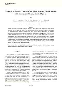
1 1. 2. 3. 4. 5.
Hydrostatic Steering System Component Layout (Semi–Powershift shown) Left Hand Turn Hose 6. Steering Pump Steering Cylinder 7. Pump Output Line Right Hand Turn Hose 8. Resonator (System Silencer) (not Supersteer) Steering Return / Lubrication Line 9. Resonator to Steering Motor Line Inlet to Pressure Regulating Valve 10. Steering Motor
All models have fitted as standard, hydrostatic steering systems that are powered when the engine is running by hydraulic pumps mounted on the rear axle. There are two basic types of fixed displacement steering pump used depending on whether the main hydraulic system has a closed centre or open centre system. Both open and closed centre hydraulic systems incorporate a steering pump as part of the hydraulic pump assemblies and both types share the main intake filter of that system. The pumps, driven by a gear straight from the P.T.O. shaft, pressurise the steering column operated steering motor. The pressurised oil from the steering motor drives the axle mounted double acting steering cylinder (2WD), or twin cylinders (4WD). The steering motor is similar across the vehicle range and is bolted to a bracket within the steering console and connected to the steering column by a splined shaft. Models with the supersteer front axle and all 175 and 190 model use a load sensing non-reactive motor. The steering column is adjustable for varying angles of tilt on all models.
604.55.111.00 – 06 – 2002
On two wheel drive units the steering cylinder is fixed at one end to the front axle beam and at the other to an eye on the spindle steering arm. On four wheel drive units two steering cylinders are used, one for each wheel. The cylinders are fixed at one end to the axle casing and the piston end to steering arms from the swivel housings. The pressure relief valve for the system is contained within the steering motor itself.
OPERATION – All models except Supersteer and 175/190 models Oil is drawn from the rear axle and into the pump through a filter, pressurised by the rotation of the gears, and expelled through the pump outlet port to the steering motor. The oil is pumped to the steering motor via a flow priority valve which restricts oil to the steering motor when the steering is not in use and diverts oil to the low pressure hydraulic system. When the steering is in use, the valve then diverts oil to the steering motor. A resonance damper filter is also in line between the flow priority valve and steering motor, this reduces the noise from the system and smooths the output from the pump. The pressurised oil when received at the steering motor is directed to the steering actuating cylinder when the steering wheel is turned.
SECTION 41 – STEERING – CHAPTER 1
5
Steering Operation Schematic 120 to 155 Models – Neutral Position
Pump Oil
Return Oil (Restricted by Cooling and Lubrication
Trapped Oil
Suction Oil 2
1. 2. 3. 4. 5. 6. 7.
Metering Unit Check Valve Non Return Valve Resonance Damper Filter (not Supersteer Models) Pump and Flow Control Valve Filter Return via Cooling and Lubrication
The steering motor incorporates a metering unit which regulates the volume of oil supplied to the cylinder so that it is proportional to the angular movement of the steering wheel. The metering unit in combination with the check valve also allows the steering to be operated MANUALLY without pressurised oil being supplied from the pump. Suction valves, item 10 Figure 2, only used on two wheel drive models, prevent cavitation in the steering cylinder as oil is transferred from a small area to a large area when the steering motor is in the neutral position.
8. 9. 10. 11. 12. 13.
Pressure Relief Valve Control Valve Sleeve Control Valve Spool Suction Valves (2WD Only) Bias Valve (2WD Only) Steering Cylinder/s
The system is fully hydrostatic and as such there is no mechanical connection between the steering column and the steering wheels. Neutral Position With the steering wheel held still, the leaf springs in the steering motor return and hold the spool and sleeve in the neutral position. This ensures no more oil is supplied to the steering cylinder, Figure 2. The trapped oil is, however, allowed to transfer between the left and right turn sides of the cylinder/s, allowing the wheels to react to the ground to provide feedback for the driver.
604.55.111.00 – 06 – 2002
6
SECTION 41 – STEERING – CHAPTER 1
Oil Flow Schematic A– Right Hand Turn B– Left Hand Turn
Pressure Supply
Return Oil (Restricted by Cooling and Lubrication
Metered Oil to Steering Cylinder
Suction Oil 3
Right Hand Turn When the steering wheel is turned the movement of the control valve spool in its sleeve forms a series of passages. During right turns the oil flows through the sleeve along a groove in the valve spool and into a passage in the steering motor housing which leads to the metering unit, Figure 3. The metering unit is turned by the drive shaft and directs oil along another set of passages in the spool and sleeve and into the steering cylinder. Return oil from the other side of the cylinder is directed through the valve spool and sleeve to a return passage in the housing.
604.55.111.00 – 06 – 2002
Left Hand Turn When turning the wheel to the left oil flows along the sleeve and operates in a similar manner as described in right hand turn, Figure 3. Manual Turning (no Power Assistance) In the event of a power steering pump failure or loss of oil pressure, the power steering system can be operated manually. Turning the steering wheel rotates the metering unit rotor and forces oil into the power steering cylinder (2WD) or cylinders (4WD). On the suction side of the metering unit, return oil flows from the cylinder and is drawn through the check valve to feed the metering unit.
SECTION 41 – STEERING – CHAPTER 1
Steering Motor Pressure Oil
7
Exhaust Oil Suction Oil 4
Steering Operation – 120 to 155 Supersteer Models – Manual Steering 1. 2. 3. 4. 5. 6.
Steering Pump Priority Valve Spool Relief Valve Check Valve Control Valve Sleeve/Spool Shock Valves
Operation – Supersteer Models The steering motor fitted to models with the supersteer front axle is a load sensing non-reactive type. The motor is designated as a 100–180, meaning that, with the use of a flow amplification valve the system can produce either 100 cc or 180 cc of oil, depending on whether the steering pump is supplying oil to the motor. When there is no
7. 8. 9. 10. 11.
Metering Unit Amplifying Valve Priority Valve Load Sense Orifice Priority Valve Orifice Check Valve
steering pump output, i.e. engine off or pump failure, the amplifying valve restricts the oil to pass through the metering unit only, thereby supplying 100 cc/rev of oil to the rams. This has the effect of increasing the amount the steering wheel needs to rotate but reducing the effort required, necessary for these emergency conditions.
604.55.111.00 – 06 – 2002
8
SECTION 41 – STEERING – CHAPTER 1
Steering pump pressure Oil
Trapped Oil
Dynamic Steering Oil
Exhaust Oil
Low Pressure Regulated Oil
Suction Oil 5
Steering Operation – 120 to 155 Supersteer Models – Engine Running, Steering Wheel Stationary 1. 2. 3. 4. 5. 6.
Steering Pump Priority Valve Spool Relief Valve Check Valve Control Valve Sleeve/Spool Shock Valves
With the engine running and the steering wheel stationary the flow priority valve directs most of the pump oil into the low pressure circuit. The pump oil supplied to the dynamic load sense line is also redirected by the steering motor control valve sleeve/spool to the low pressure circuit. Oil is also trapped in the steering rams by the control valve
604.55.111.00 – 06 – 2002
7. 8. 9. 10. 11.
Metering Unit Amplifying Valve Priority Valve Load Sense Orifice Priority Valve Orifice Check Valve
sleeve/spool. If the front wheels hit a large obstruction, pressure increase in the rams is relieved by the shock valves, which open and return oil to the low pressure circuit. Smaller shocks to the front wheels are relieved by the check valve, item 11.
SECTION 41 – STEERING – CHAPTER 1
9
Steering Pump Pressure Oil
Low Pressure Regulated Oil
Dynamic Steering Oil
Exhaust Oil
Metering Unit Pressure Oil
Suction Oil 6
Steering Operation – 120 to 155 Supersteer Models – Engine Running, Steering Wheel Speed less than 20 rev/min. 1. 2. 3. 4. 5. 6.
Steering Pump Priority Valve Spool Relief Valve Check Valve Control Valve Sleeve/Spool Shock Valves
With the engine running, turning the steering wheel at speeds less than 20 rpm will not induce any additional oil, via the amplification valve, and
7. 8. 9. 10. 11.
Metering Unit Amplifying Valve Priority Valve Load Sense Orifice Priority Valve Orifice Check Valve
therefore all the oil for the steering rams is provided by the dynamic sensing oil, passing through the metering unit.
604.55.111.00 – 06 – 2002
10
SECTION 41 – STEERING – CHAPTER 1
Steering Pump Pressure Oil
Low Pressure Regulated Oil
Dynamic Steering Oil
Exhaust Oil
Metering/Amplifying Valve Oil
Suction Oil 7
Steering Operation – 120 to 155 Supersteer Models – Engine Running, Steering Wheel Speeds greater than 20 rev/min. 1. 2. 3. 4. 5. 6.
Steering Pump Priority Valve Spool Relief Valve Check Valve Control Valve Sleeve/Spool Shock Valves
As the speed at which the steering wheel is rotated increases, the amplification valve progressively allows more oil to the motor and hence to the steering rams.
604.55.111.00 – 06 – 2002
7. 8. 9. 10. 11.
Metering Unit Amplifying Valve Priority Valve Load Sense Orifice Priority Valve Orifice Check Valve
This system provides fast rates of turning when required and more subtle steering movements at slower speeds, i.e. straight line corrections.
SECTION 41 – STEERING – CHAPTER 1
Steering Motor Pressure Oil
11
Exhaust Oil Suction Oil 8
Steering Operation – 175 and 190 Models – Manual Steering 1. 2. 3. 4. 5.
Steering Pump Priority Valve Spool Relief Valve Check Valve Control Valve Sleeve/Spool
Operation – 175 and 190 Models The steering motor fitted to 175 and 190 models is a load sensing non-reactive type. The motor is designated as a 100–180, meaning that, with the use of a flow amplification valve the system can produce either 100 cc or 180 cc of oil, depending on whether the steering pump is supplying oil to the motor. When
6. 7. 8. 9. 10.
Shock Valves Metering Unit Amplifying Valve Priority Valve Load Sense Orifice Check Valve
there is no steering pump output, i.e. engine off or pump failure, the amplifying valve restricts the oil to pass through the metering unit only, thereby supplying 100 cc/rev of oil to the rams. This has the effect of increasing the amount the steering wheel needs to rotate but reducing the effort required, necessary for these emergency conditions.
604.55.111.00 – 06 – 2002
12
SECTION 41 – STEERING – CHAPTER 1
Steering pump pressure Oil
Trapped Oil
Dynamic Steering Oil
Exhaust Oil
Lubrication Oil
Suction Oil 9
Steering Operation – 175 and 190 Models – Engine Running, Steering Wheel Stationary 1. 2. 3. 4. 5.
Steering Pump Priority Valve Spool Relief Valve Check Valve Control Valve Sleeve/Spool
With the engine running and the steering wheel stationary the flow priority valve directs most of the pump oil into the lubrication circuit. The pump oil supplied to the dynamic load sense line is also redirected by the steering motor control valve sleeve/spool to the lubrication circuit. Oil is also trapped in the steering rams by the control valve
604.55.111.00 – 06 – 2002
6. 7. 8. 9. 10.
Shock Valves Metering Unit Amplifying Valve Priority Valve Load Sense Orifice Check Valve
sleeve/spool. If the front wheels hit a large obstruction, pressure increase in the rams is relieved by the shock valves, which open and return oil to the lubrication circuit. Smaller shocks to the front wheels are relieved by the check valve, item 10.
SECTION 41 – STEERING – CHAPTER 1
Steering Pump Pressure Oil
Lubrication Oil
Dynamic Steering Oil
Exhaust Oil
Metering Unit Pressure Oil
Suction Oil
13
10 Steering Operation – 175 and 190 Models – Engine Running, Steering Wheel Speed less than 20 rev/min. 1. 2. 3. 4. 5.
Steering Pump Priority Valve Spool Relief Valve Check Valve Control Valve Sleeve/Spool
With the engine running, turning the steering wheel at speeds less than 20 rpm will not induce any additional oil, via the amplification valve, and
6. 7. 8. 9. 10.
Shock Valves Metering Unit Amplifying Valve Priority Valve Load Sense Orifice Check Valve
therefore all the oil for the steering rams is provided by the dynamic sensing oil, passing through the metering unit.
604.55.111.00 – 06 – 2002
14
SECTION 41 – STEERING – CHAPTER 1
Steering Pump Pressure Oil
Lubrication Oil
Dynamic Steering Oil
Exhaust Oil
Metering/Amplifying Valve Oil
Suction Oil 11
Steering Operation – 175 and 190 Models – Engine Running, Steering Wheel Speeds greater than 20 rev/min. 1. 2. 3. 4. 5.
Steering Pump Priority Valve Spool Relief Valve Check Valve Control Valve Sleeve/Spool
As the speed at which the steering wheel is rotated increases, the amplification valve progressively allows more oil to the motor and hence to the steering rams.
604.55.111.00 – 06 – 2002
6. 7. 8. 9. 10.
Shock Valves Metering Unit Amplifying Valve Priority Valve Load Sense Orifice Check Valve
This system provides fast rates of turning when required and more subtle steering movements at slower speeds, i.e. straight line corrections.
SECTION 41 – STEERING – CHAPTER 1
15
Steering /Lubrication priority Valve – 175 and 190 Models Located on the output port of the steering pump, the steering / lubrication priority valve (1), determines the oil flow to the steering and lubrication circuits depending on the demand of the steering, which is given priority when in use. A. Tube to oil cooler B. Connection to steering motor C. Dynamic Load sense line to the steering motor
12 Priority valve operation Engine OFF – Manual Steering There is no output from the steering pump, therefore the spool is kept to the right by the spring pressure.
E
A D C
Engine ON – Steering wheel stationary or rotation speed less than 20 rpm
B
BSD2315A
13
Output from the steering pump (E) enters the priority valve and flows through the middle of the priority valve spool. The oil from the left side of the spool (D) provides the oil for the load sensing circuit. When the steering wheel is stationary this is directed to the lube circuit through the steering motor.
E
A D C
B
BSD2315B
14 When the steering wheel is rotated slowly the oil in the load sense circuit supplies the rams, via the steering motor. Due to the oil being used for either lube or ram supply the pressure reduction in gallery (D) allows pressure applied to the right hand end of the spool (A) to move the spool to the left and allow more oil flow to the lube circuit (B).
E
A D C
B
BSD2315C
15
604.55.111.00 – 06 – 2002
16
SECTION 41 – STEERING – CHAPTER 1
Engine ON – Steering wheel rotation speed greater than 20 rpm The increase in steering wheel rotation speed causes a pressure drop in the motor and allows pump oil to supply the rams. The pressure drop in the pump circuit, with the resultant drop in pressure at gallery (A), allows the spring to move the spool to the right and provide the steering motor priority of oil flow from the pump through gallery (C).
E
A D C
B
BSD2315D
16
41 000 – FAULT FINDING IMPORTANT: When effecting a repair the cause must be corrected to avoid a repeat failure.
PROBLEM
POSSIBLE CAUSE
REMEDY
No steering or excessive effort to steer
1. Air in system
1. Check for loose connections or damaged tubing. Purge system of air.
2. Steering system relief valve 2. Check system pressure. sticking/faulty
Steering wanders
3. Worn pump
3. Inspect and repair.
4. Leaking steering cylinder
4. Inspect and repair.
5. Broken or damaged steering 5. Inspect and column coupling required.
replace
as
6. Damaged or worn metering unit 6. Inspect and required.
replace
as
1. Excessive play in steering 1. Inspect and linkage joints required.
replace
as
2. Leaking steering cylinder
2. Inspect and repair.
3. Damaged or worn metering unit 3. Inspect and required.
replace
Drift to Left, Two Wheel Drive only
1. Bias valve faulty
1. Replace or repair
Front wheels surge when steering
1. Leaking steering cylinder
1. Inspect and repair.
604.55.111.00 – 06 – 2002
as
2. Damaged or worn metering unit 2. Inspect and replace as required
SECTION 41 – STEERING – CHAPTER 1
17
41 000 – SYSTEM TESTING When the hydrostatic steering system is in operation, the pressure of oil supplied by the steering pump, item 3, Figure 17, (120 to 155 models) to the steering motor, can rise towards the maximum setting of the steering motor relief valve, which is 170 bar (2465 lbf/in2) depending on tractor model. Depending on the model and the transmission option fitted the return oil from the steering motor is either returned into the top cover, full powershift transmissions or into the transmission side cover, all other transmission types.
3
1
2 60–41–023
TI
17 The return oil is used to provide the low pressure circuit oil for all 120 to 155 Models for components such as, front and rear differential locks, P.T.O. clutch and brake and four wheel drive systems, where fitted. For 175 and 190 Models the return oil is used to supply the lubrication circuits, the low pressure oil being supplied from the variable displacement pump via a regulating valve.
18 Steering Pump There is no relief valve in the steering pump. The following practical test will determine if steering pump output is sufficient to allow satisfactory operation of the steering system.
Steering Test 1. Set engine speed to 1000 rev/min. 2. Turn steering quickly from lock to lock. If steering is operating correctly the reaction of the steering should be immediate with no time delay between turning the steering wheel and movement of the wheels. At full lock the relief valve in the steering motor should be heard to blow and the engine speed should drop to approximately 970 rev/min.
19
604.55.111.00 – 06 – 2002
18
SECTION 41 – STEERING – CHAPTER 1
Steering Relief Valve Pressure Test IMPORTANT: There is no relief valve in the steering/low pressure pump and the following pressure test must only be performed as specified below. Failure to observe this precaution may result in severe damage to the hydraulic pump. 1. Turn steering onto full left hand lock. 2. Disconnect left hand turn feed hose at steering cylinder. 3. Install a 0–6000 lbf/in2 pressure gauge FT. 8503A, item 1, Figure 20, using adaptor FT8503–8, item 2, Figure 20 and a locally procured 7/16 JIC male x 9/16 JIC male adaptor, item 3, Figure 20. Using kit 292870 install adaptor 293874 and 291318 into the place of the banjo fitting of the steering hydraulic cylinder. 4. Start tractor and set engine speed to 1450 rev/min. Turn steering wheel to the left with a pull of approximately 22 N (2.25 kgf, 5 lbf) and observe the pressure reading. NOTE: The use of a force greater than 5 lbf. at the rim of the steering wheel may lead to slightly inaccurate readings due to the pumping action of the hydrostatic steering motor. If the steering test was satisfactory but the pressure readings are away from specification the relief valve in the steering motor must be adjusted. The pressure reading should be:– 186 bar (2700 lbf/in2) for all models. 5. If the system pressure is not to specification proceed to Relief Valve Adjustment. Differential Pressure Differential pressure is the difference in pressure between the supply and sump ports on the steering motor. Measured (gauge) pressure is equal to the relief valve setting plus system back pressure. System back pressure should be 16 bar (232 lbf/in2) for all models. The flow of oil on leaving the steering motor returns to the pump body for distribution to the low pressure and lubrication circuits. The pressure of oil returning from the steering motor is regulated at a pressure of 16.0 bar (232.0 lbf/in2), by the low pressure regulating valve at 2100 revs/min. As the pressure is regulated, excess oil in the low pressure circuit flows through the regulating valve, into an adjacent lubrication circuit relief valve which limits the pressure of oil in the lubrication circuit to 7 bar (100 lbf.in2).
604.55.111.00 – 06 – 2002
1
3 60–41–024
2 TI
20
SECTION 41 – STEERING – CHAPTER 1
19
1 13 2 12 3
4
9
B
10 T
11
P
5
8
7
A
6
21 Steering Motor Relief Valve Adjustment 1. 2. 3. 4. 5. 6. 7.
Plug Steering Shaft Relief Valve Fabricated Steering Motor Output Hose Tractor Tubes to Steering Cylinder Fabricated Hose for Pump Supply to Steering Motor Pressure Gauge 0–5000lbf.in2
8. 9. 10. 11. 12. 13.
Size 8 ORS Swivel Running Tee Size 10 ORS Swivel Running Tee Pressure Gauge 0–500lbf.in2 Size 6 ORS Blanking Cap Spring Adjuster
604.55.111.00 – 06 – 2002
20
SECTION 41 – STEERING – CHAPTER 1
Relief Valve Adjustment – All Models With reference to Figure 21. NOTE: To adjust the steering system relief valve it is necessary to remove the steering motor from the steering bracket, to gain access to the hexagon headed adjusting screw. 1. Disconnect the steering motor from the steering bracket, as detailed previously in this Chapter, and remove from the tractor. 2. Fabricate suitable test hoses to connect from the tractor pressure and return tubes. Connect the hoses into locally procured tee pieces and install pressure gauges. Start the engine and idle between 1450 and 1500 rev/min. Run the tractor until the transmission oil reaches normal working temperature of approximately 68°C (155°F).
604.55.111.00 – 06 – 2002
3. With the engine running, turn the steering motor shaft to obtain full lock. The pressure gauge reading at point ‘A’ should read 186 bar (2700 lbf.in2). The gauge pressure at point ‘B’ should be in the region of 16 bar (235 lbf.in2). 4. To establish actual (differential) pressure subtract gauge ‘B’ reading from the gauge ‘A’ reading. The differential pressure should be to the specification of: Gauge ‘A’ 186 bar (2700 lbf.in2) minus Gauge ‘B 235 lbf.in2 (16 bar) = 2465 lbf.in2 (170 bar) on all models 5. If the pressure readings are not correct, reset the adjuster (item 13), 21, using an 8mm hexagon key. Half a turn on the adjuster equates to approximately 200 lbf.in2 (13.8 bar).
SECTION 41 – STEERING – CHAPTER 1
21
41 204 – STEERING MOTOR - OVERHAUL 5
15
16
14
1
17 18 19
13
12 11 10
2
5
3 9
5 8 7 6
60–41–001
5
4
TI
22 Steering Motor (120 to 155 Models 2WD + 4WD Less Supersteer) 1. 2. 3. 4. 5. 6. 7. 8. 9. 10.
Pin Centering Springs Retaining Bolts Dowel Pin Bolt ‘O’ Ring Seal (Kit) End Plate Rotor and Stator Assembly Manifold Plate Drive Shaft Retainer
11. 12. 13. 14. 15. 16. 17. 18. 19.
Ball Relief Valve Seat Relief Valve (Kit items) Spring Complete Assembly Ball Pin Thrust Bearing and Washers Spacer
NOTE: Parts/Motors are common between the two steering pumps, with the exception of items 7,10,12 and 13, Figure 22.
604.55.111.00 – 06 – 2002
22
SECTION 41 – STEERING – CHAPTER 1
Removal 1. Position the tractor on a hard level surface and apply the parking brake. 2. To gain access to the steering motor :– Raise the engine hood Remove the left hand steering column console Remove left hand engine side cover 3. Disconnect the four supply/return tubes and ‘O’ ring seals from the steering motor and cap the ends of the tubes. 4. Remove the roll pin from the drive collar to separate the steering shaft, Figure 23. 5. Remove the four bolts at the base of the steering column and slide the steering motor from the upper section of the steering column, Figure 23. 6. Remove the steering motor from the front of the cab through the engine compartment.
60–41–018
TI
23
Dlsassembly 1. With the steering motor connectors removed note position of the non return valve. 2. Hold the steering motor securely in a vice using a tube connector as shown in, Figure 24. NOTE: The position of the pin bolt must remain the same on re–assembly. 3. Remove the end plate bolts, end plate and ‘O’ ring, Figure 24.
60–41–002
TI
24 4. Remove metering unit, valve plate and ‘O’ ring seals, note mating surfaces for correct re–assembly, Figure 25.
60–41–003
TI
25
604.55.111.00 – 06 – 2002
SECTION 41 – STEERING – CHAPTER 1
23
5. Lift out rotor drive-shaft, Figure 26.
60–41–004
TI
26 6. Unscrew the check valve retainer, Figure 27 and shake out the check and suction valves.
60–41–005
TI
27 7. Remove the relief valve assembly, Figure 28. IMPORTANT: The relief valve must be set to the correct pressure setting on re–assembly. Follow the correct procedure as detailed under the heading ‘Pressure relief valve setting’, of this Chapter.
60–41–006
TI
28 8. Remove the inner and outer valve sleeves, bearings and thrust washer, Figure 29. NOTE: When removing spool and sleeve ensure drive pin is in a horizontal position so that it cannot fall into an internal gallery and make removal difficult.
60–41–007
TI
29
604.55.111.00 – 06 – 2002
24
SECTION 41 – STEERING – CHAPTER 1
9. Once spool is disassembled from the body ensure oil seal is removed, Figure 30.
60–41–008
TI
30 IMPORTANT: Upon re–assembly ensure washer, item 1, Figure 31 is installed with chamfer towards the valve sleeve. 10. Remove the control valve spool and sleeve, Figure 31.
1
60–41–009
TI
31 11. Remove centering springs, Figure 32. NOTE: Arrangement of the leaves must remain the same upon re–assembly. 12. Remove drive pin, Figure 32. 13. Push inner sleeve from outer sleeve. 14. Remove ‘O’ ring and back-up ring.
60–41–010
TI
32
604.55.111.00 – 06 – 2002
SECTION 41 – STEERING – CHAPTER 1
25
33 Steering Motor (120 to 155 Models with Supersteer and all 175 and 190 Models) 1. 2. 3. 4. 5. 6. 7. 8. 9. 10. 11. 12. 13. 14. 15.
Relief Valve Spring for Relief Valve Shock Valve Shock Valve Dust Seal Ring LS Check Valve, Ball LS Check Valve, Screw Shaft Seal Bearing Ring Cross Pin Set of Springs Housing, Spool and Sleeve Thread Bushing Ball ø 8.5 mm
Inspection 1. Wash all parts in a suitable solvent to remove any foreign particles and dry with a clean lint free cloth or compressed air. 2. Inspect valve sleeves for, damage or wear. Minor burrs or scratches can be removed with a fine
16. 17. 18. 19. 20. 21. 22. 23. 24. 25. 26. 27. 28. 29. 30.
Amplification Orifice Amplification Spool Spring Plug Drive Link Spacer O–ring Distributor Plate Gear Wheel Set O–ring End Cover Washer Special Screw Special Screw Name Plate
abrasive. Ensure all parts are thoroughly cleaned prior to re-assembly. 3. Check leaf springs for damage. Replace if necessary. 4. Discard all ‘O’ ring seals and replace with new seals on re-assembly.
604.55.111.00 – 06 – 2002
26
SECTION 41 – STEERING – CHAPTER 1
Re-Assembly 1. Assemble inner and outer sleeves so that the leaf spring slots align. 2. Install the drive pin, Figure 34.
60–41–010
TI
34 3. Install the leaf springs and push fully into position, Figure 35.
60–41–012
TI
35 4. Install leaf spring retainer, and bearing, Figure 36. NOTE: The inner bearing race must be positioned with the chamfer side facing the spool, 31.
60–41–009
TI
36 5. Apply a light coating of hydraulic oil onto the sleeve item 2 and insert into the steering motor body, item 3, Figure 37. 6. Coat the ‘O’ ring and back-up ring, item 4, Figure 37, with hydraulic fluid and position them onto the seal installer guide. – Use New Holland special tool No. 293388 to install oil seal type kin–ring. – Use New Holland special tool No. 294056 to install oil seal type roto–glyd. 60–41–013
TI
37 604.55.111.00 – 06 – 2002
SECTION 41 – STEERING – CHAPTER 1
27
7. Position the seal guide tool into the sleeve and push down with a twisting action, Figure 38. 8. Remove tools once the seal has seated.
60–41–014
TI
38 9. With the seal installed in the motor body refit control valve, Figure 39. NOTE: Ensure that the Drive is in a horizontal position to aid re–assembly.
60–41–015
TI
39 10. Once the control valve is seated correctly refit the check and suction valves, Figure 40. 11. Screw the check valve down to just below the surface of the housing.
60–41–005
TI
40 12. Refit the ‘O’ Ring and place the end plate in position.
60–41–016
TI
41
604.55.111.00 – 06 – 2002
28
SECTION 41 – STEERING – CHAPTER 1
Metering Unit Reassembly 1. To aid reassembly install the control valve into the housing so that the drive pin is perpendicular to the front face of the housing. 2. Install drive link into the steering motor body, Figure 42, ensuring that the link engages correctly over the drive pin.
60–41–004
TI
42 3. Assemble the metering unit rotor and stator and install new lightly greased ‘O’ rings to either side of the stator, Figure 43. 4. Assemble the rotor and stator onto the drive link.
60–41–003
TI
43 5. Install the end plate and bolts, ensure the pin bolt(1) is fitted in position ‘7’. Tighten the bolts in two steps, first to 8 lbf.ft (10.8 Nm) and then to 21 lbf.ft (28.4 Nm) in sequence as shown, Figure 44.
4
6
2
1
1 7
3 5
44
604.55.111.00 – 06 – 2002
SECTION 41 – STEERING – CHAPTER 1 6. Install the relief valve assembly, items 1, 2 and 3 Figure 45., leaving the plug, item 4 out until after the relief valve has been adjusted. 7. Check to ensure the motor turns freely without binding. IMPORTANT: The relief valve must be set to the correct pressure setting after the motor has been re–assembled. Follow the correct procedure as detailed under ‘Pressure relief valve setting’, of this Chapter. 8. After the relief valve has been correctly set re–install the steering motor onto the mounting bracket and tighten the securing bolts to a torque value of 10–15 lbf ft(13–20Nm). 9. Reconnect the steering hoses, tighten to a torque value of 10–15 lbf ft (13–20Nm). 10. Purge the air from the system by operating the steering system from lock to lock until the system functions correctly.
29
4
1 2 3 60–41–006
TI
45
STEERING COLUMN REMOVAL AND INSTALLATION NOTE: The component parts of the steering column as listed are serviced separately. Removal 1. Remove the steering wheel, if required. 2. Remove the lower steering column cover complete with multi–function switches. 3. Remove the upper steering column cover on mechanical transmission models. Prior to removing the upper cover on Hi–Lo and semi–powershift models remove the shuttle lever from steering column. 4. Remove the instrument console side panels. 5. Remove the four securing bolts securing the column to the frame, Figure 46.
60–41–028
TI
46
6. Lift the column clear of the steering shaft and clear of the instrument console, Figure 47.
60–41–027
TI
47
604.55.111.00 – 06 – 2002
30
SECTION 41 – STEERING – CHAPTER 1
7. Remove the pin from the spacer at the bottom of the column and remove the steering shaft and spacer, Figure 48. Inspection 1. Inspect the steering shaft universal joint and lower rubber coupling. Replace if any free play is evident. 2. Inspect the column assembly, if damaged or the bushes are worn a new assembly will be required. 60–41–025
TI
48 Installation 1. Place spacer and steering shaft onto the steering motor and install pin. 2. Carefully place the steering column through the instrument console and over the steering shaft, ensuring flat sides are aligned. 3. Replace the securing bolts at the top of the column. Tighten to 23 Nm (17 lbf.ft). 4. Refit the upper and lower column covers and shuttle switch if fitted. 5. Refit the instrument console panels. 6. Refit the steering wheel.
60–41–026
TI
49
604.55.111.00 – 06 – 2002
SECTION 41 – STEERING – CHAPTER 1
31
TWO WHEEL DRIVE STEERING CYLINDER – REMOVAL AND INSTALLATION (OP. 41 216)
1 2
7
6 5
4 3
60–41–029
TI
1 Steering Cylinder Installation – Two Wheel Drive (Standard Duty) 1. 2. 3. 4.
Nut Washer Nut Washer
Removal 1. Stand the unit on a hard level surface and position the front wheel in the straight ahead position. 2. Disconnect flexible pipes, cap the open pipe ends and remove hose clamps. 3. Position of flexible pipes and orientation of connectors must be the same upon re–assembly.
5. 6. 7.
Cylinder Mounting Bracket Spacer Bolt
4. Remove the nut securing the cylinder rod ball joint to the steering arm and separate the joint, Figure 1. 5. Remove the steering cylinder to axle pivot pin and remove the steering cylinder from the vehicle. 6. Installation is the reversal of the removal procedure.
604.55.111.00 – 06 – 2002
32
SECTION 41 – STEERING – CHAPTER 1
Steering Cylinder Overhaul – Two Wheel Drive
13
2
1
3
12 11 10
4 9 8
7
6
5
2 1. 2. 3. 4. 5. 6. 7.
Cylinder Lockring Bearing Gland ‘O’ Ring Seal Wiper Seal
Steering Cylinder Assembly – Two Wheel Drive 8. Gland Lockring 9. Cylinder Rod 10. Retaining Ring 11. Piston 12. Seal 13. Seal
1. Using appropriate circlip pliers, remove the gland lockring. 2. Using a punch, push the steering cylinder gland into the cylinder and remove the wire locking ring. 3. Pull the rod and gland assembly from the cylinder. 4. Remove the nut from the cylinder rod and disassemble to replace seals.
60–41–030
3 5. Inspect the bore of the cylinder and replace if scored. 6. Reassemble the cylinder in the reverse to disassembly, lubricating all components as assembled. Replace all seals supplied in the service seal kit. NOTE: The seal located in the centre of the gland is replaceable.
4
604.55.111.00 – 06 – 2002
SECTION 41 – STEERING – CHAPTER 1
33
FOUR WHEEL DRIVE STEERING CYLINDERS – REMOVAL AND INSTALLATION (OP. 41 216) 1
2
3 4
5
7
6 5
1. 2. 3. 4.
Pivot Pin Pivot Pin D Shaped Washer Spacer
Steering Cylinder Installation – Four Wheel Drive 5. Spacer 6. Circlip 7. Spacer
1. Stand the unit on a hard level surface and position the front wheel in the straight ahead position. 2. Disconnect flexible pipes, cap the open pipe ends and remove hose clamps. NOTE: Position of flexible pipes and orientation of connectors must be the same upon re–assembly. 3. Remove the snap ring retaining the steering arm to the cylinder piston pivot pin, item 6, Figure 5 and remove the pivot pin. 4. Remove the steering cylinder fixed end pivot pin retaining bolt and withdraw the pivot pin, item 1, Figure 5 . Remove the cylinder from the vehicle. 5. Installation is the reversal of the removal procedure.
6
Steering Stop Adjustment 1. Turn the wheels to full lock and adjust steering stop to ensure tyres or mudguards do not touch the side of the tractor and that the steering cylinders have not reached the end of their travel.
604.55.111.00 – 06 – 2002
34
SECTION 41 – STEERING – CHAPTER 1
Steering Cylinder Overhaul – Four Wheel Drive
1
2
8 3
7
4
6
5 7 1. 2. 3. 4.
Cylinder Wiper Seal Retaining Ring Gland Nut
Steering Cylinder Assembly – Four Wheel Drive 5. Cylinder Rod 6. Gland and Seal Assembly 7. Piston 8. Nut
1. Using appropriate ‘C’ spanner, unscrew and remove the gland nut. 2. Using a punch, push the steering cylinder gland into the cylinder and remove the wire locking ring. 3. Pull the rod and gland assembly from the cylinder. 4. Remove the nut from the cylinder rod and disassemble to replace seals.
8 5. Inspect the bore of the cylinder and replace if scored. 6. Reassemble the cylinder in the reverse to disassembly, lubricating all components as assembled. Replace all seals supplied in the service seal kit. NOTE: The seal located in the centre of the gland is replaceable.
9
604.55.111.00 – 06 – 2002