Article pubs.acs.org/IECR
A Highly Stable Ti/TiHx/Sb−SnO2 Anode: Preparation, Characterization and Application Dan Shao,† Wei Yan,*,†,‡ Xiaoliang Li,† Honghui Yang,† and Hao Xu*,† †
Department of Environmental Science and Engineering, Xi’an Jiaotong University, Xi’an 710049, China Suzhou Academy of Xi’an Jiaotong University, Suzhou 215021, China
‡
S Supporting Information *
ABSTRACT: Low service life limits the industrial application of the titanium-based Sb−SnO2 anode. To improve its stability, a titanium hydride interlayer is fabricated to construct a three-layer anode, Ti/TiHx/Sb−SnO2. Titanium hydride was prepared by reducing precoated titanium oxide in aqueous solution via electrochemical process, and it acted as a binder between the Ti and Sb−SnO2 phases. Cyclic voltammetry, electrochemical impedance spectroscopy, and the accelerated lifetime test were also conducted to elucidate the positive effect of the TiHx interlayer. Results show that Ti/TiHx/Sb−SnO2 not only possesses better stability but has higher oxygen evolution potential and lower electron transfer resistance compared with Ti/Sb−SnO2. Essential characterizations were conducted including scanning electron microscopy, energy disperse spectroscopy, and X-ray diffraction. The mechanism of lifetime enhancement is also proposed. The performances of the electrodes on degrading three different organics manifest that the degradation performance of the electrode strongly relies on the electrode stability.
1. INTRODUCTION In the past two decades, more and more attention has been attracted on studying electrochemical oxidation treatment (EOT) of wastewater with high oxygen evolution potential (OEP), high stable and low cost anodes.1−4 Dimensional stable anodes (DSAs) are series of electrodes fabricated by coating transition metal oxides, such as RuO2, IrO2, TiO2, SnO2, PbO2, MnO2, and Ta2O5, onto a metal substrate (mainly titanium).5−9 RuO2, IrO2, SnO2, and PbO2 are the most commonly used four coating materials for DSAs, and their synthetical performances (catalytic activity, stability, and cost) are proved to be better than those of conventional anodes (metal, carbon, etc.) and newly developed anodes (boron-doped diamond, etc.).10−12An antimony-doped SnO2 (Ti/Sb−SnO2) anode, which possesses high OEP (higher than RuO2, IrO2, and PbO2), appropriate cost (lower than RuO2 and IrO2), and low secondary contamination (lower than PbO2), is one of the most promising anodes for EOT of wastewater.12−15 However, the main drawback of the Ti/Sb−SnO2 electrode is the short service life in anodic polarization conditions, which limits its further applications.16,17 The factors that affect the stability of the Ti/Sb−SnO2 electrode are very complicated and have not been studied thoroughly. It is generally believed that the weak attachment between the Ti substrate and Sb−SnO2, and the passivation of the Ti substrate are the main factors leading to its low stability.18−21 The most simple and effective method to enhance the stability of Ti/Sb−SnO2 is introducing an interlayer.22 However, the OEP value of heterogeneous active interlayer (Pt, RuO2, and IrO2) is not as high as that of Sb−SnO2, and the OEP of the electrode was lowered inevitably.17 Therefore, a novel and economical interlayer insertion technique is still desired. © 2014 American Chemical Society
In this paper, titanium hydride (TiHx) was introduced as an interlayer to enhance the stability of the Ti/Sb−SnO 2 electrode. It is worth noting that this idea was inspired by the previous work of Baronetto et al.,23 where it was demonstrated that the ohmic loss between the catalyst layer and the Ti substrate could be eliminated by creating a hydride layer on the titanium surface. We envisaged that such a TiHx layer would not lower the OEP of the Ti/Sb−SnO2 due to the high OEP of TiO2 transformed from TiHx calcination. But, the direct reduction of the Ti substrate that we have performed before could not improve the stability of the Ti/Sb−SnO2 electrode effectively, which may be due to the poor protection of the Ti substrate (Figure S1 in the Supporting Information). Thus, it is decided to coat a TiOx layer on the surface of Ti to protect the Ti substrate first and then electrochemically reduce TiOx to TiHx prior to further Sb−SnO2 coating. The special contributions of this TiHx interlayer in terms of electrode electrochemical properties and stability were confirmed and analyzed through a series of material characterizations, electrochemical characterizations, and accelerated lifetime tests. Furthermore, a possible deactivation mechanism of Ti/TiHx/Sb−SnO2 was also discussed to explore the reason for stability enhancement. In addition, three target pollutants model compounds, including acid red G (ARG), methylene blue (MB), and sodium lignosulphonate (lignin), which are typical contaminants in acid dye wastewater, basic dye wastewater, and papermaking wastewater, respectively, were used to confirm the significant impact of the electrode stability on the performance of the electrode in environmental wastewater treatment. Received: Revised: Accepted: Published: 3898
November 7, 2013 January 13, 2014 February 19, 2014 February 19, 2014 dx.doi.org/10.1021/ie403768f | Ind. Eng. Chem. Res. 2014, 53, 3898−3907
Industrial & Engineering Chemistry Research
Article
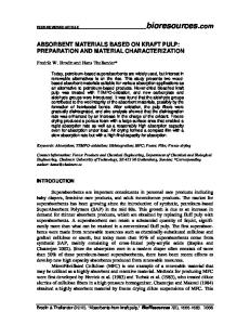
Figure 1. Images of the interlayer and surface layer of Ti/TiHx/Sb−SnO2. (a) Digital photo of the TiOxand TiHx interlayer (left: TiOx; right: black TiHx); (b) SEM image of the TiOx interlayer; (c) SEM image of the TiHx interlayer; (d) SEM image of the surface Sb−SnO2 layer.
2. EXPERIMENTAL SECTION 2.1. Electrode Preparation. Titanium plates (40 mm × 10 mm × 0.5 mm, BaoTi Ltd., China) were used as the substrate. The substrate pretreatment method is listed in the literature.24 The dried substrate was first dip coated using the solution comprising 80% tetrabutyl orthotitanate (TBOT), 20% alcohol, and 0.1 M HNO3 and then dried in an oven at 373 K and heated at 773 K for 15 min to form a TiOx-loaded plate. The TiOx-loaded plate was reduced by a electrochemical cathodic reduction process (two-electrode system; graphite plate was used as the counter electrode) in a sodium sulfate aqueous solution (room temperature, cathodic current density 10 mA· cm−2, reduction time 5 min), and its gray color turned black (Figure 1a represented this specific color change). Sb deposition was performed for 10 s in ethanediol solution containing 0.2 M SbCl3, 0.1 M HNO3, and 0.01 M sodium citrate at the cathodic current density of 15 mA·cm−2. Following that, Sn deposition was performed in another ethanediol solution for 120 s containing 0.5 M SnCl2, 0.1 M HNO3, and 0.01 M sodium citrate at the cathodic current density of 4 mA·cm−2. Then, the above electrodeposition procedure was repeated for several cycles. Coating loading amount could be regulated accurately by adjusting the number of electrodeposition cycles. After electrodeposition, the electrode was dried and then heated in oven at 773 K for 1 h for the transformation of the precursor tin and antimony into a Sb−SnO2 oxide layer. In addition, electrodes without an interlayer (Ti/Sb−SnO2) were prepared in the same way to compare the performance with Ti/TiHx/Sb−SnO2 electrodes. 2.2. Characterizations. The morphology and element content of samples were examined by field-emission scanning electron microscopy (FE-SEM, JEOL, JSM-6700F) equipped with an energy-dispersive X-ray spectroscopy (EDS) detector. The crystal structure of prepared samples were identified by an
X’pert PRO MRD diffractometer (XRD, PANalytical, Holland) using Cu K source (λ = 0.15416 nm), with a scanning angle (2θ) ranging from 10° to ∼80°. Inductively coupled plasma atomic emission spectroscopy (ICP-AES, ICPE-9000, Shimadzu, Japan) was used to determine the concentration of Sn and Sb element in the electrolyte versus time in the accelerated lifetime test. Aqueous samples were first filtered by a membrane (pore size of 0.45 μm) and then digested by microwave. 2.3. Electrochemistry Experiments. All electrochemistry experiments were performed in 0.5 M H2SO4 aqueous solution (0.5 L) at room temperature. Cyclic voltammetry (CV, scan rate: 0.05 V·s−1) and electrochemical impedance spectroscopy (EIS) were performed on an electrochemical workstation (CHI 660D, Shanghai Chenhua, China) to analyze the electrochemical property of the electrodes. The fabricated electrode (double-faced, effective area 2 cm2) was used as the working electrode and two copper plates (3 cm × 3 cm) were used as the counter electrode. The equilibrium potential of the working electrode was set to 0 V (vs Ag/AgCl) in the EIS test. The frequency range was from 0.1 Hz to 105 Hz. The amplitude of the potential was 5 mV. The accelerated lifetime test was carried out at high current density (200 mA·cm−2) using electrochemical workstation (LK3000A, Tianjin Lanlike, China). The electrode sample served as the working electrode (double-faced, effective electrode area 2 cm2) and two copper plates (3 cm × 3 cm) were employed as the counter electrodes. The sample was regarded as a deactivated electrode when the cell voltage of the test system reached to 10 V. 2.4. Environmental Pollutants Degradation. Chemical pure acid red G (ARG, C18H13N3Na2O8S2, CAS no. 3734-676), methylene blue (MB, C16H18ClN3S, CAS no. 61-73-4), and sodium lignosulphonate (Lignin, C20H24Na2O10S2, CAS no. 8061-51-6) were dissolved in pure water (18 MΩ·cm) as model 3899
dx.doi.org/10.1021/ie403768f | Ind. Eng. Chem. Res. 2014, 53, 3898−3907
Industrial & Engineering Chemistry Research
Article
wastewater samples. The pure water is fabricated in a water purification system (EPED-S2-D, EPED, China). The concentration of each solution was defined as 1000 mg·L−1. The volume of each solution was 0.5 L. The adopted effective area of the anode (fabricated electrode) and cathode (graphite sheet) was 90 cm2, respectively. The anodic current density was fixed to 20 mA·cm−2. The current efficiency of organics degradation on each electrode is used to assess the catalytic oxidizing ability of the electrode. According to Faraday’s law, the current efficiency is defined as the ratio of theoretical quantity of electric charge to actual passed quantity of electric charge. Theoretical quantity of electric charge is calculated by the measured COD removal of each target pollutant. The examination of the relationship between the electrode stability and its degradation performance was carried out at a fixed current density of 20 mA·cm−2. The electrodes were tested continuously throughout 50 days. ARG, MB, and lignin solution were replaced twice a day. The current efficiency was measured every 10 days.
3. RESULTS AND DISCUSSION 3.1. Characterizations. 3.1.1. Morphology and Crystal Structure. Morphologies of the interlayer and the surface layer of the Ti/TiHx/Sb−-SnO2 are shown in Figure 1. The unreduced TiOx interlayer (Figure 1b) shows a microstructure with irregular column arrays (∼5 μm height), like isolated islands. Figure 1c shows the microstructure of TiHx. The production of TiHx could be simply expressed by the following equation: TiOx + x H 2O + xe− → TiHx + xOH− (aqueous medium)
Figure 2. Crystalline structure of Ti/TiHx/Sb−SnO2. (a) TiOx and TiHx interlayer; (b) surface Sb−SnO2 layer.
(1)
3.1.3. Electron Transfer Resistance. The effect of the TiHx interlayer on the electrode impedance was analyzed by EIS. The Nyquist plots of freshly prepared Ti/Sb−SnO2 and Ti/TiHx/ Sb−SnO2 are shown in Figure 3b. Qualitatively, the arc diameter for Ti/TiHx/Sb−SnO2 is smaller than that for Ti/ Sb−SnO2, which indicates that the introduction of the TiHx interlayer lowers electrode impedance and favors electron transfer. The equivalent circuit that best fits the experimental EIS data is a Rs(RfQ) combination, as shown in Figure 3b. Rs, Rf, and Q correspond to solution resistance, electrode film resistance, and the constant phase element (CPE), respectively. The calculated Rf value of Ti/TiHx/Sb−SnO2 is 17.38 Ω·cm2, which is less than that of Ti/Sb−SnO2 (46.77 Ω·cm2). Since the same Sb−SnO2 was coated on both electrodes, such a difference in electrode film resistance could be attributed to the improvement of the coating−substrate interface condition in Ti/TiHx/Sb−SnO2. From the perspective of electron transfer, direct electron transfer from Sb−SnO2 coating to Ti substrate will encounter an interface resistance. The introduction of a buffer layer may minimize this effect. This result is consistent with those reported by Baronetto et al.23 3.2. Electrode Stability. 3.2.1. Loading Amount Effect. The loading amount of the coating strongly affected the electrode stability.26 Zhao et al. reported that the loading amount of Sb−SnO2 on a TiO2 nanotube electrode (Ti/TiO2− NTs) was 2.14 mg·cm−2, two times larger than traditional Ti/ Sb−SnO2. The accelerated lifetime of Ti/TiO2−NTs/Sb− SnO2 was 45 h while that of traditional Ti/Sb−SnO2 was only 22 h (0.1 M Na2SO4, 100 mA·cm−2).27 Generally, the optimal loading amount for Ti/Sb−SnO2 (without interlayer) existed as
Interestingly, several bulges immersed between the islands, which may be the consequence of hydrogen incorporation. When the compact Sb−SnO2 layer was loaded (Figure 1d), the interlayer was completely filled and covered. The crystal structures of the above layers could be revealed by Figure 2. The unreduced interlayer showed TiO2 anatase structure (ICDD 01-083-2243, main diffraction peaks at 25.4°, 37.0°, 37.9°, 38.7°, and 48.2°) but with low diffraction peak intensity that means the crystallization was undeveloped; thus, the following hydrogen reduction may be realized easier on this undeveloped crystalline. After reduction, the anatase TiO2 structure on the interlayer surface was replaced by the titanium hydride (ICDD 01-078-2216, diffraction peaks at 35.3°, 40.9°, 59.4°, 70.9°, and 74.6°). The external Sb−SnO2 layer showed a unique SnO2 cassiterite structure (ICDD 01-077-0447, three main diffraction peaks at 26.6°, 33.9°, and 51.8°) without Ti detection indicated the well coverage of the Ti substrate. Antimony was also undetected, which may due to its incorporation into the SnO2 lattice. 3.1.2. Oxygen Evolution Potential. To ensure the electrode catalytic efficiency for electrooxidation, the OEP of the electrode should not be decreased by the interlayer. The CV curves of freshly prepared Ti/Sb−SnO2 and Ti/TiHx/Sb− SnO2 in 0.5 M H2SO4 solution are shown together in Figure 3a. It is found that the OEP of Ti/TiHx/Sb−SnO2 (∼2.15 V vs Ag/AgCl) is slightly higher than that of Ti/Sb−SnO2 (∼2.05 V vs Ag/AgCl). The transformation of the TiHx interlayer to TiOx (0 < x ≤2) during the heating process of electrode fabrication may be the dominant factor, since TiOx is inert for oxygen evolution and hence increased the OEP slightly.25 3900
dx.doi.org/10.1021/ie403768f | Ind. Eng. Chem. Res. 2014, 53, 3898−3907
Industrial & Engineering Chemistry Research
Article
Figure 4. Service life of (a) Ti/Sb−SnO2 and (b) Ti/TiHx/Sb−SnO2 as a function of the Sb−SnO2 loading (0.5 M H2SO4, anodic current density of 200 mA·cm−2, room temperature).
Figure 3. Electrochemcal properties of freshly prepared Ti/Sb−SnO2 and Ti/TiHx/Sb−SnO2 (in 0.5 M H2SO4). (a) Cyclic voltammograms of the first three runs (scan rate: 0.05 V·s−1); (b) Nyquist plots (0.1− 105Hz) and equivalent circuit for EIS data fitting.
a relative high level around 7−8 V (broken circle in Figure 5a), it remained relative steady and lasted for about 3 h. When this transition period was completed, the cell voltage increased rapidly. From Figure 5a, the electrode service process could be divided into two periods: a steady period and an unstable period. In the first period, the external Sb−SnO2 layer was dissolving or detaching. However, in the second period, the inner layer may play an important role on keeping for a relative high performance of this electrode, and SEM and XRD analysis could reveal this. When the cell voltage reached the specific platform (Figure 5b), the profile of the column arrays structure (islands) of the interlayer emerged again (dark area), and residual Sb−SnO2 component could also be found at that time (bright area). However, when the cell voltage increased to 10 V, the coating was hard to recognize except the cracked interlayer (Figure 5c). The XRD patterns corresponding to the above two SEM images also demonstrate such severe coating loss (Figure 5d). SnO2 was still the main component and at the beginning of the platform, and other multiple phases (TiO2, Ti, and Sb2Ox) just emerged. However, SnO2 is hard to identify on the deactivated electrode, and the anatase TiO2 phase is dominant. From the above results, it could be found that the specific cell voltage platform may indicate the existence of an inner Ti−Sn− Sb ternary oxide solid solution layer, which struggled with the electrolyte penetration when the outer layer had already dissolved or detached. The element analysis (EDS results in Table 1) also provides a side proof. The atom ratios of Ti, Sn, and Sb on the freshly prepared Ti/TiHx/Sb−SnO2 surface are 6.34%, 24.46%, and 2.53%, respectively. However the atom ratios of Ti, Sn, and Sb are 20.03%, 8.80%, and 1.01% on the
a peak value.17 In this study, it was similar for the Ti/Sb−SnO2 (Figure 4a, ∼3.1 mg·cm−2) electrode. The initial increase in service life with increase of oxide loading amount can also be explained by a mechanism in which the coating is detached layer by layer, which means that the thicker the coating the higher the service life; this is the case when the loading amount is below a critical value. The decrease of service life when the loading amount exceeds the critical value can be explained by the mechanical stress generated by the difference of thermal expansion between the coating and the Ti substrate. However, the Ti/TiHx/Sb−SnO2 electrodes show good performances with the loading amount of Sb−SnO2 between 2.5 and ∼5.1 mg·cm−2 (Figure 4b). It is worth noting that the longest accelerated lifetime for Ti/TiHx/Sb−SnO2 is 60−80 h and that for Ti/Sb−SnO2 is only 14−16 h (0.5 M H2SO4, anodic current density of 200 mA·cm−2, room temperature). It is clear that the TiHx interlayer improves the electrode service life and extends the optimum ranges of the Sb−SnO2 loading amount. Although an excessive loading amount is not necessary, the extended optimum ranges of the Sb−SnO2 loading amount may simplify the electrode preparation process and increase the qualification rate of the electrode once it is applied in industry. 3.2.2. Accelerated Lifetime Test. Figure 5a describes the recorded time profile of cell voltage during the accelerated electrolysis of the Ti/TiHx/Sb−SnO2 (0.5 M H2SO4, anodic current density of 200 mA·cm−2, room temperature). The electrode could be regarded as stable in the first 60 h for the slight variation of cell voltage. After 60 h, the cell voltage increased clearly. Interestingly, when the cell voltage reached to 3901
dx.doi.org/10.1021/ie403768f | Ind. Eng. Chem. Res. 2014, 53, 3898−3907
Industrial & Engineering Chemistry Research
Article
Figure 5. Accelerated lifetime test result of Ti/TiHx/Sb−SnO2 (0.5 M H2SO4, anodic current density of 200 mA·cm−2, room temperature). (a) Typical accelerated lifetime curve of Ti/TiHx/Sb−SnO2 (the specific cell voltage platform was within a dotted line circle); (b) surface morphology of the electrode when the cell voltage reached the platform; (c) surface morphology of the electrode when the cell voltage reached 10 V; (d) XRD patterns of the electrode (1, when the cell voltage reached the platform; 2, when the cell voltage reached 10 V).
Table 1. Atom % Variation of Ti, Sn, and Sb Obtained on Ti/TiHx/Sb−SnO2 in Different Periodsa period
Ti %
Sn %
Sb %
O%
1 2 3
6.34 20.01 30.70
24.46 8.80 5.15
2.53 1.00 2.88
73.01 70.19 61.27
Table 2. Accelerated Lifetime Data for Ti-Based Sb−SnO2 Electrode in Some Recent Literature anode type Ti/Sb−SnO2 Ti/TiO2−NTs/ Sb−SnO2 Ti/TiO2−NTs/ Sb−SnO2 Ti/Sb−SnO2
a
(1) Freshly prepared Ti/TiHx/Sb−SnO2; (2) when the cell voltage reached the platform; (3) when the cell voltage reached 10 V.
presumed Ti−Sn−Sb ternary oxide solid solution layer. On the deactivated electrode, such ratios are 30.70%, 5.15%, and 2.88%, respectively. Relative content variation of these three elements reflects the loss of Sb−SnO2 coating on the deactivated electrode surface. Especially, oxygen content of the deactivated electrode is only 61.27%, lower than 66.6%, which indicates the detection of Ti metal. The EDS result also proves that the Ti/TiHx/Sb−SnO2 would not be deactivated until nearly all the Sb−SnO2 was lost. The typical accelerated lifetimes of Ti/Sb−SnO2 and Ti/ TiHx/Sb−SnO2 are ∼14 h and ∼72 h, respectively. Table 2 has listed the results of accelerated lifetime tests of the Ti/Sb− SnO2 electrodes in recent literatures.3,28−32 Ti/TiHx/Sb−SnO2 in this study shows good performance under the similar test condition, which indicates the importance of the TiHx interlayer. 3.3. Possible Mechanism of Stability Enhancement. 3.3.1. Formation of a Solid Solution Interlayer. According to above results, it could be concluded that the TiHx interlayer plays an important role in stability enhancement. Our hypothesis is that TiHx could be heated with electrodeposited Sn and Sb to form stable solid solution oxide structure. Theoretically, the formation of a metal oxides solid solution is
Ti/SnO2−Sb−Bi Ti/SnO2− Sb2O4−CNT− Cr3C2 Ti/TiHx/Sb− SnO2
electrolyte
anodic current density
accelerated lifetime
literature
0.5 M NaOH 0.1 M H2SO4 0.1 M Na2SO4 0.5 M H2SO4 0.5 M H2SO4 1M H2SO4
≤200 mA·cm−2
12 h
27
100 mA·cm−2
36 h
28
100 mA·cm−2
42 h
29
100 mA·cm−2
12.1 h
30
100 mA·cm−2
0.8 h
3
100 mA·cm−2
7h
31
0.5 M H2SO4
200 mA·cm−2
72 h
this work
highly dependent on the ionic radius among the metal elements. When the ratio of radii difference between two metal ions in oxides is less than 15%, the metal oxide mixture could be highly intermixed and exist in the form of solid solution.33 The ionic radii of Ti(IV), Sn(IV), Sb(V) are 68, 71, 62 pm, respectively.34 The different ratios of ionic radii among Ti(IV) and Sn(IV), Ti(IV) and Sb(V), and Sn(IV) and Sb(V) are 13%, 4%, and 9%, respectively, which indicates the possible formation of Ti−Sn−Sb ternary oxides solution. Transformation of TiHx to a solid solution layer may actually consist of two stages (also illustrated in Figure 6). The first one is the TiHx decomposition: TiHx → Ti + H 2 ↑ 3902
(occurs beyond ∼673 K)
(2)
dx.doi.org/10.1021/ie403768f | Ind. Eng. Chem. Res. 2014, 53, 3898−3907
Industrial & Engineering Chemistry Research
Article
However, pure Ti substrate lacks the advantage of the Ti− Sn−Sb mixture and does not have the same solid solution formation ability as TiHx. 3.3.2. Ti/Sb−SnO2 Deactivation Mechanism. It is generally believed that the formation of an undoped TiO2 layer between the substrate and the coating is the immediate cause of Ti/Sb− SnO2 deactivation (which is asmentioned in the abstract). The remote cause depends on the properties of the Sb−SnO2 coating. However, besides severe dissolution in strong acid media, Sb−SnO2 coating has other inherent defects, which could not be completely overcomed. For instance, traditional Ti/Sb−SnO2 (via dip or brush coating-pyrolysis) electrodes possess typical “crack-mud” structure due to the inner mechanical stress of the coating.36 Such a loosened coating layer would be penetrated by electrolyte during electrolysis.28 Another defect of Sb−SnO2 may be the easy detaching (layer by layer), which can be explained on the mechanism for oxygen gas evolution in which a certain degree of nonstoichiometry (SnO2−x) is present in the Sb−SnO2 coating as discussed elsewhere.17 This initial defect involves many active sites, where the reaction
Figure 6. Scheme of a transformation from TiHx to Ti−Sn−Sb oxide solid solution layer.
SnO(2−x) + H 2O → SnO(2−x)(·OH) + H+ + e−
This new generated Ti may be amorphous and much active, and its structure may be much porous due to the H2 release (foaming agent property35) The melting Sn and Sb may also penertrate into the vacancies, which may increase the possibility of forming mixture of Ti, Sn, and Sb metals. The second stage is the combination of oxygen and metals, three reaction happen simultaneously and form a solid solution layer: Ti + O2 → TiO2
(3)
Sn + O2 → SnO2
(4)
Sb + O2 → Sb2 O5
(5)
(6)
happens with generation of adsorbed hydroxyl radicals ·OH. A further reaction may take place with an increase in oxygen stoichiometry, which is still below 2 at this stage: SnO(2−x)(·OH) → SnO(2−x+y) + y H+ + ye−
(7)
This modification of the electrode surface increases the surface coating inner stress resulting in coating detachment. Underlying coating layers then undergo series of detaching cycles. Even when the coating is compact (fabricated through the electrodeposition-thermal oxdiation method), such an effect is still unignorable. No matter electrolyte penetration or coating detachment, when the electrolytes reach to the interface between the substrate and the coating, Ti substrate corrosion begins, and the
Simultaneous in situ reactions may also benefit the cocrystallization of TiO2, SnO2, and Sb2O5, and solid solution formation takes advantage of it.
Figure 7. Possible deactivation mechanisms of Ti/Sb−SnO2 and Ti/TiHx/Sb−SnO2. 3903
dx.doi.org/10.1021/ie403768f | Ind. Eng. Chem. Res. 2014, 53, 3898−3907
Industrial & Engineering Chemistry Research
Article
dissolution happened, so the detected metal elements amount increased smoothly. However, when the Ti−Sn−Sb ternary oxide inner layer was corroded, both the detected Sn and Sb variations showed clear inflections. It could be inferred that large piece detachment is inhibited, since considerable Sn and Sb elements have incorporated into the solid solution layer, and the dissolution mechanism is dominant. The Ti/TiHx/Sb−SnO2 electrode would not be deactivated until almost all the Sb−SnO2 coating is lost. Moreover, coating consumption is a much slower process than the direct electrolyte penetration. Ti/TiHx/Sb−SnO2 is more resistant to direct electrolyte penetration, so it possesses much longer lifetime than that of Ti/Sb−SnO2. In addition, the time cost of coating consumption that in fact determines the length of service life depends on the coating loading amount, anodic current density, electrolyte type, and pH value of the solution. The contributions of the TiHx interlayer insertion are summarized as follows: (1) advantages of Sb−SnO2 coating are not weakened; (2) substrate−coating charge transfer is benefited; (3) inner mechanical stress of the coating is decreased; and (4) the electrode deactivation mechanism is changed. The above four contributions of TiHx insertion may lead to the accomplishment of the stability enhancement and OEP maintenance purposes for Ti/Sb−SnO2. 3.4. Organic Pollutants Degradation and Electrode Stability. In the actual electrooxidation wastewater treatment process, the significance of the high electrode stability is the maximum retention of the high oxidizing ability of the electrode throughout the service period. Since earlier years, it has been proved that Sb-doped SnO2 is a strong organic removal catalyt due to its strong hydroxyl radical generation ability.37 In the initial period of the service of the electrode, both Ti/Sb−SnO2 and Ti/TiHx/Sb−SnO2 electrode showed similar and good performances. In Figure 9a, the UV−vis absorption (∼300 nm: benzene ring absorption; ∼400 nm: naphthalene ring absorption; ∼500 nm: azo linkage absorption) of acid dye ARG was significantly decreased after 1 h treatment. Especially, the azo linkage absorption almost disappeared after 1 h treatment, which reflected the strong color removal ability of the Sb−SnO2 electrode. For basic dye MB, the UV−vis absorption of aromatic ring (UV region) and chromophoric groups (600−700 nm) were also decreased obviously after 1 h treatment by Sb−SnO2 (Figure 9b). For lignin, the characterization absorption peak around 280 nm and the visual absorption were also decreased obviously after 1 h treatment (Figure 9c). The aromatic ring of lignin was first opened by the attack of hydroxyl radical and then decomposed to small molecues and CO2 eventually. For ARG, MB, and lignin, the COD removal efficiencies were around 50%, 25%, and 25% after 1 h treatment and around 85%, 60%, and 65% after 3 h treatment, respectively (insets in Figure 9a−c). The novel Ti/ TiHx/Sb−SnO2 electrode shows a little better ability in terms of both UV−vis absorption decrease and COD removal efficiency due to its higher OEP discussed before (Figure 3a). However, as service goes on, the current efficiency of the less stable Ti/Sb−SnO2 electrode declined obviously (Figure 9d). After 50 days, compared to the initial values, the degradation current efficiency of ARG, MB, and lignin decreased by 26.53%, 19.06%, and 25.05%, respectively. The main reasons for current efficiency decline are the loss of effective catalyst coating and the increase of useless heat productivity due to the risen electrode resistance. While the current efficiency of the novel electrode remained stable even after 50 days. A highly stable
insulated titanium oxide forms at the breakthrough point initially and then spreads along the substrate−coating interface. Both the penetration and insulate layer growth are quick processes. When all the effecitive substrate is corroded, not all the coatings are consumed. That is the reason for some nonignorable Sb−SnO2 residue still exists on the deactivated electrode. This procedure is illustrated in the left half of Figure 7. For Ti/Sb−SnO2 in this study, although a more compact Sb−SnO2 layer was made by the electrodeposition-thermal oxidation method, such a mechanism is still valid. 3.3.3. Ti/TiHx/Sb−SnO2 Deactivation Mechanism. For Ti/ TiHx/Sb−SnO2, the deactivation mechanism may be different. A possible deactivation procedure for Ti/TiHx/Sb−-SnO2 could be proposed (right half in Figure 7). Because of the defense of the inner Ti−Sn−Sb solid solution layer, the substrate is well protected. Even when the electrolytes break through the weak point of the compact Sb−SnO2 coating, they only reach to the solid solution layer and could not contact the Ti substrate. The inner mechanical stress of the coating is also decreased by the solid solution layer that acts as a buffer layer. Decreased inner mechanical stress would lower the coating mechanical detaching rate. The insulate layer would not form until almost all Sn and Sb elements are deprived from the Ti− Sn−Sb ternary solid solution layer. Then, the electrode could be regraded as a pure TiO2-coated electrode with poor conductivity. This is the reason that no obvious Sb−SnO2 structure is detected on the XRD pattern of the totally deactivated electrode. The nearly complete Sb−SnO2 loss reflected by SEM and EDS results could also proved such inference. Figure 8 may confirm the doping element loss process of the inner solid solution layer. Despite large detached particles, the
Figure 8. Dissolved Sn and Sb element weight of Ti/TiHx/Sb−SnO2 electrode (Sn−SnO2 loading 2.5 mg·cm−2) when the cell voltage reached the platform nearby in the accelerated electrolysis (0.5 M H2SO4, anodic current density of 200 mA·cm−2, effect electrode area of 2 cm2).
amount of Sn and Sb lost from the Ti−Sn−Sb ternary oxide inner layer was evaluated by ICP-AES when the cell voltage reached the platform during accelerated electrolysis. When the platform period began, the rate of Sn and Sb detachment increased. This phenomenon could be ascribed to the change of Sb−Sn loss mechanism. It has been mentioned that large pieces of Sb−SnO2 (>0.45 μm) were removed in the pretreatment and could not be detected by ICP-AES. Before the platform period, both large piece coating detachment and coating 3904
dx.doi.org/10.1021/ie403768f | Ind. Eng. Chem. Res. 2014, 53, 3898−3907
Industrial & Engineering Chemistry Research
Article
Figure 9. Performance of the electrodes of ARG, MB, and lignin degradation. (a) UV−vis spectra variation of ARG after 1 h treatment (1, Ti/Sb− SnO2; 2, Ti/TiHx/Sb−SnO2) and COD removal efficiency (triangle, Ti/Sb−SnO2; dot, Ti/TiHx/Sb−SnO2); (b) UV−vis spectra variation of MB after 1 h treatment (1, Ti/Sb−SnO2; 2, Ti/TiHx/Sb−SnO2) and COD removal efficiency (triangle, Ti/Sb−SnO2; dot, Ti/TiHx/Sb−SnO2); (c) UV−vis spectra variation of lignin after 1 h treatment (1, Ti/Sb−SnO2; 2, Ti/TiHx/Sb−SnO2) and COD removal efficiency (triangle, Ti/Sb−SnO2; dot, Ti/TiHx/Sb−SnO2); (d) COD removal current efficiency variations during the 50 service days of the electrodes.
increased obviously (its energy consumption values were nearly doubled when 50 days passed). The above results demonstrate that the pollutants degradation performance of the electrode relies on the electrode stability strongly. The previous effort on the electrode stability enhancement is meaningful. Environmental cost-effective strategy is working on the novel Ti/TiHx/Sb−SnO2 electrode. The novel electrode is proved to be better than the Ti/Sb− SnO2 electrode in many ways for organic wastewater treatment.
electrode means the effective use of precious electrode material because the electrode would not need to be recreated and replaced. A highly stable electrode also saves electric energy as the total energy consumption is proportional to the total cell voltage that is dependent on the electrode conductivity. Table 3 listed the variations of electric energy consumption (kWh·gCOD−1) of the Ti/Sb−SnO2 electrode and the novel Ti/TiHx/Sb−SnO2 electrode in ARG, MB, and lignin treatment. The data of the novel Ti/TiHx/Sb−SnO2 electrode changed slightly during 50 days, while the data of the less stable Ti/Sb−SnO2 electrode
4. CONCLUSIONS A specific titanium hydride interlayer (electrochemically reduced from titanium oxide in aqueous medium) has been used for the service lifetime improvement of the titanium-based antimony-doped tin dioxide anode. The typical accelerated lifetimes of Ti/Sb−SnO2 and Ti/TiHx/Sb−SnO2 are ∼14 and ∼72 h, respectively (in 0.5 M H2SO4, anodic current density: 200 mA·cm−2, Sb−SnO2 loading: 2.5 mg·cm−2). It must be noted that the oxygen evolution inhibition property of Ti/Sb− SnO2 is also maintained. The film resistance is also slightly decreased, which is consistent with the previous report.23 The mechanism of stability improvement could be ascribed to the well protection of the substrate by a firm Ti−Sn−Sb oxide solid solution interlayer. The solid solution layer changes the electrode deactivation mechanism, and the electrode would not be deactivated until nearly all the Sb−SnO2 coating is lost. Coating consumption rate determined the lifetime of the novel
Table 3. Electric Energy Consumption of ARG, MB, and Lignin Degradation by the Ti/Sb−SnO2 Electrode and the Ti/TiHx/Sb−SnO2 Electrode during 50 Service Days electric energy consumption (kWh·gCOD−1) Ti/Sb−SnO2
Ti/TiHx/Sb−SnO2
service day
ARG
MB
lignin
ARG
MB
lignin
1 10 20 30 40 50
0.048 0.056 0.064 0.073 0.084 0.109
0.068 0.072 0.079 0.091 0.097 0.106
0.194 0.204 0.241 0.273 0.318 0.351
0.043 0.044 0.045 0.044 0.044 0.045
0.065 0.065 0.065 0.065 0.065 0.066
0.181 0.182 0.182 0.186 0.186 0.186 3905
dx.doi.org/10.1021/ie403768f | Ind. Eng. Chem. Res. 2014, 53, 3898−3907
Industrial & Engineering Chemistry Research
Article
chlorophenol for wastewater treatment. J. Appl. Electrochem. 1999, 29, 147−151. (14) Li, X. Y.; Cui, Y. H.; Feng, Y. J.; Xie, Z. M.; Gu, J. D. Reaction pathways and mechanisms of the electrochemical degradation of phenol on different electrodes. Water Res. 2005, 39, 1972−1981. (15) Wang, Y. H.; Cheng, S. A.; Chan, K. Y.; Li, X. Y. Electrolytic generation of ozone on antimony- and nickel-doped tin oxide electrode. J. Electrochem. Soc. 2005, 152, 197−200. (16) Lipp, L.; Pletcher, D. The preparation and characterization of tin dioxide coated titanium electrodes. Electrochim. Acta 1997, 42, 1091− 1099. (17) Correa-Lozano, B.; Comninellis, Ch.; De Battisti, A. Service life of Ti/SnO2-Sb2O5 anodes. J. Appl. Electrochem. 1997, 27, 970−974. (18) Xu, L. K.; Scantlebury, J. D. A study on the deactivation of an IrO2-Ta2O5 coated titanium anode. Corros. Sci. 2003, 45, 2729−2740. (19) Da Silva, L. M.; Fermades, K. C.; De Faria, L. A.; Boodts, J. F. C. Electrochemical impedance spectroscopy study during accelerated life test of conductive oxides: Ti/(Ru + Ti + Ce)O2-system. Electrochim. Acta 2004, 49, 4893−4906. (20) Panic, V.; Dekanski, A.; Miskovic-Stankovic, V. B.; Milonjic, S.; Nikolic, B. On the deactivation mechanism of RuO2-TiO2/Ti anodes prepared by the sol-gel procedure. J. Electroanal. Chem. 2005, 579, 67− 76. (21) Vicent, F.; Morallón, E.; Quijada, C.; Vázquez, J. L.; Aldaz, A.; Cases, F. Characterization and stability of doped SnO2 anodes. J. Appl. Electrochem. 1998, 28, 607−612. (22) Zanta, C.; Michaud, P. A.; Comninellis, Ch.; De Andrade, A. R.; Boodts, J. Electrochemical oxidation of p-chlorophenol on SnO2Sb2O5 based anodes for wastewater treatment. J. Appl. Electrochem. 2003, 33, 1211−1215. (23) Baronetto, D.; Kodintsev, I. M.; Trasatti, S. Origin of ohmic losses at Co3O4/Ti electrodes. J. Appl. Electrochem. 1994, 24, 189−194. (24) Zheng, Y. H.; Su, W. Q.; Chen, S. Y.; Wu, X. Z.; Chen, X. M. Ti/SnO2−Sb2O5−RuO2/α-PbO2/β-PbO2 electrodes for pollutants degradation. Chem. Eng. J. 2011, 174, 304−309. (25) Kitsuka, K.; Kaneda, K.; Ikematsu, M.; Iseki, M.; Mushiake, K.; Ohsaka, T. Ex situ and in situ characterization studies of spin-coated TiO2 film electrodes for the electrochemical ozone production process. Electrochim. Acta 2009, 55, 31−36. (26) Montilla, F.; Morallon, E.; De Battisti, A.; Vazquez, J. L. Preparation and characterization of antimony-doped tin dioxide electrodes. J. Phys. Chem. B 2004, 108, 5036−5043. (27) Li, P. Q.; Zhao, G. H.; Cui, X.; Zhang, Y. G.; Tang, Y. T. Constructing stake structured TiO2-NTs/Sb-doped SnO2 electrode simultaneously with high electrocatalytic performance for complete mineralization of refractory aromatic acid. J. Phys. Chem. C 2009, 113, 2375−2383. (28) Adams, B.; Tian, M.; Chen, A. C. Design and electrochemical study of SnO2-based mixed oxide electrodes. Electrochim. Acta 2009, 54, 1491−1498. (29) Zhao, G. H.; Cui, X.; Liu, M. C.; Li, P. Q.; Zhang, Y. G.; Cao, T. C.; Li, H. X.; Lei, Y. Z.; Liu, L.; Li, D. M. Electrochemical degradation of refractory pollutant using a novel microstructured TiO2 nanotubes/ Sb-doped SnO2 electrode. Environ. Sci. Technol. 2009, 43, 1480−1486. (30) Cui, X.; Zhao, G. H.; Lei, Y. Z.; Li, H. X.; Li, P. Q.; Liu, M. C. Novel vertically aligned TiO2 nanotubes embedded with Sb-doped SnO2 electrode with high oxygen evolution potential and long service time. Mater. Chem. Phys. 2009, 13, 314−321. (31) Ding, H. Y.; Feng, Y. J.; Lu, J. W. Study on the service life and deactivation mechanism of Ti/SnO2-Sb electrode by physical and electrochemical methods. Russ. J. Electrochem. 2010, 46, 72−76. (32) Hu, F. P.; Dong, Z. Q.; Cui, X. W.; Chen, W. X. Improved SnO2-Sb2O4 based anode modified with Cr3C2 and CNT for phenol oxidation. Electrochim. Acta 2011, 56, 1576−1580. (33) Chen, X. M.; Chen, G. H. Stable Ti/RuO2-Sb2O5-SnO2 electrodes for O2 evolution. Electrochim. Acta 2005, 50, 4155−4159. (34) Kong, H. S.; Lu, H. Y.; Zhang, W. L.; Lin, H. B.; Huang, W. M. Performance characterization of Ti substrate lead dioxide electrode
electrode. In addition, the pollutants degradation performance of the electrode relies on the electrode stability strongly, and the highly stable Ti/TiHx/Sb−SnO2 electrode exhibits better degradation efficiency and consistency than the Ti/Sb−SnO2 electrode.
■
ASSOCIATED CONTENT
S Supporting Information *
SEM image of Ti substrate after direct electrochemical reduction. This material is available free of charge via the Internet at http://pubs.acs.org.
■
AUTHOR INFORMATION
Corresponding Authors
*E-mail: (W.Y.)
[email protected]. *E-mail: (H.X.)
[email protected]. Notes
The authors declare no competing financial interest.
■
ACKNOWLEDGMENTS This work was supported by the Fundamental Research Funds for the Central Universities of China (2011JDGZ15), Science and Technology Support Program of Jiangsu Province (SBE201038213), and Applied Basic Research Program of Suzhou (SYN201004).
■
REFERENCES
(1) Trasatti, S. Electrocatalysis: Understanding the success of DSA®. Electrochim. Acta 2000, 45, 2377−2385. (2) Jara, C. C.; S-Banda, G. R.; Arratia, R. S.; Campino, J. S.; Aguilera, M. I. Improving the stability of Sb doped Sn oxides electrode thermally synthesized by using an acid ionic liquid as solvent. Chem. Eng. J. 2011, 171, 1253−1262. (3) Zhuo, Q. F.; Deng, S. B.; Yang, B.; Huang, J.; Yu, G. Efficient electrochemical oxidation of perfluorooctanoate using a Ti/SnO2-SbBi anode. Environ. Sci. Technol. 2011, 45, 2973−2979. (4) Chen, G. H. Electrochemical technologies in wastewater treatment. Sep. Purif. Technol. 2004, 38, 11−41. (5) Kötz, R.; Stucki, S.; Carcer, B. Electrochemical waste water treatment using high overvoltage anodes. Part I: Physical and electrochemical properties of SnO2 anodes. J. Appl. Electrochem. 1991, 21, 14−20. (6) Cui, Y. H.; Feng, Y. J.; Liu, Z. Q. Influence of rare earths doping on the structure and electro-catalytic performance of Ti/Sb-SnO2 electrodes. Electrochim. Acta 2009, 54, 4903−4909. (7) M-Huitle, C. A.; Ferro, S. Electrochemical oxidation of organic pollutants for the wastewater treatment: Direct and indirect processes. Chem. Soc. Rev. 2006, 35, 1324−1340. (8) Electrochemistry for the Environment; Comninellis, Ch., Chen, G. H., Eds.; Springer: Berlin, Germany, 2010; pp 55−85. (9) Ribeiro, J.; De Andrade, A. R. Characterization of RuO2-Ta2O5 coated titanium electrode microstructure, morphology, and electrochemical investigation. J. Electrochem. Soc. 2004, 151, D106−D112. (10) Zhao, G. H.; Zhang, Y. G.; Lei, Y. Z.; Lv, B. Y.; Gao, J. X.; Zhang, Y. N.; Li, D. M. Fabrication and electrochemical treatment application of a novel lead dioxide anode with superhydrophobic surfaces, high oxygen evolution potential, and oxidation capability. Environ. Sci. Technol. 2010, 44, 1754−1759. (11) Feng, Y. J.; Li, X. Y. Electro-catalytic oxidation of phenol on several metal-oxide electrodes in aqueous solution. Water Res. 2003, 37, 2399−2407. (12) Comninellis, Ch. Electrocatalysis in the electrochemical conversion/combustion of organic pollutants for waste water treatment. Electrochim. Acta 1994, 39, 1857−1862. (13) Polcaro, A. M.; Palmas, S.; Renoldi, F. On the performance of Ti/SnO2 and Ti/PbO2 anodes in electrochemical degradation of 23906
dx.doi.org/10.1021/ie403768f | Ind. Eng. Chem. Res. 2014, 53, 3898−3907
Industrial & Engineering Chemistry Research
Article
with different solid solution interlayers. J. Mater. Sci. 2012, 47, 6709− 6715. (35) Sarajan, Z.; Soltani, M.; Khabushan, J. K. Foaming of Al-Si by TiH2. Mater. Manuf. Processes 2011, 26, 1293−1298. (36) Feng, Y. J.; Cui, Y. H.; Liu, J. F.; Logan, B. E. Factors affecting the electro-catalytic characteristics of Eu doped SnO2/Sb electrode. J. Hazard. Mater. 2010, 178, 29−34. (37) Comninellis, Ch. Electrocatalysis in the electrochemical conversion/combustion of organic pollutants for wastewater treatment. Electrochim. Acta 1994, 39, 1857−1862.
3907
dx.doi.org/10.1021/ie403768f | Ind. Eng. Chem. Res. 2014, 53, 3898−3907