ROUTING IN A HIERARCHICAL STRUCTURE Piet Van Mieghem AReNA Alcatel Corporate Research Francis Wellesplein 1, B-2018 Antwerp (BELGIUM)
[email protected] ABSTRACT Routing in a given hierarchical structure is discussed. The work is inspired by the ATM Forum’s PNNI specification. As a general conclusion, we argue that any routing problem that has a solution in a single (flat) network, is also tractable and feasible in a hierarchy. INTRODUCTION Let us assume that we are able to construct a hierarchical structure of a network topology (see Van Mieghem, 1998b). A hierarchical structure is just another topological representation of the original network with some additional features.
The most important property of a hierarchy is the levelstructure that draws on information condensation (node and link aggregation) to yield scalablility. Each level k in a hierarchical structure represents the complete original network, however, in a different degree of detail. Hence, if the hierarchy contains N levels, then the hierarchical structure exhibits in some sense a N-fold redundancy. The lowest level (k = 0) is but the original network, already divided into subnets (or in the language of PNNI (ATMF, 1996) peer groups). The subsequent levels (k>0) are condensed forms of the underlying levels. In particular, each subnet on a lower level is represented by a single item, that is called a complex (or logical) node in PNNI.
Highest-level Peer Group Logical Link
A
C
B
PG(A)
PG(C) A.3
A.1
C.1
PG(B)
B.4 C.2
B.2 A.2 B.3 B.1
A.1.2
A.1.1
A.1.3 A.1.4
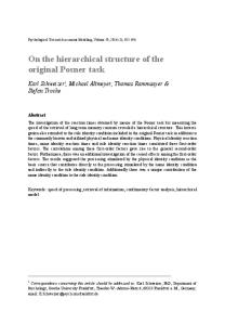
Figure 1. A hierarchical structure based on the specifications of PNNI where a subnet is coined a peer group, denoted as PG(.).
That complex node is the parent of each node in the underlying lower level subnet (or peer group). More general, complex nodes on higher levels are ancestors of the nodes on different levels they represent. Earlier (Van Mieghem, 1997, 1998b), we have given estimates how to divide an original network into peer groups and how many hierarchical levels a network is about to have. Here, we will concentrate on how to route in a hierarchical structure. We have already shown (Van Mieghem, 1997) that important savings in computational effort can be achieved when we dispose of a hierarchical structure of the original network. These earlier estimates motivate a deeper and more concrete discussion. THE PRINCIPLE Suppose a path is to be found between a source A and a destination B. The basic routing principle in a hierarchy consists of top-down level routing as follows:
(1) Search for that level k where the ancestor of A and the ancestor of B belong to one logical subnet. (2) Construct at that level k the path, Pk, over complex nodes from A’s ancestor to B’s ancestor. (3) Specify path Pk in ever greater detail by descending in the hierarchy to lower levels until the physical level (k=0) is reached. We will demonstrate that this principle holds in general. Whatever routing problem, i.e. QoS (source) routing, multicast routing or hop by hop routing, is considered, the above recipe is applicable. Before concentrating to its details, we present a different approach inspired by the way the PNNI specification determines the designated transfer list (DTL), which is a hierarchical representation of the path from A→B. In particular, the routing is established using the view point of a level k=0 node in a hierarchy.
A.3
B
A.1.2
A.1.1
A.1.3
C
A.2
A.1.4
Figure 2. The world view according to physical node A.1.4 is called the ‘projected’ topology of A.1.4.
The world according to such a physical node consists of all its own ancestors on all levels. For instance, in Figure 1, the view point of the physical node A.1.4 is the union of its own peer group A.1, that of its parent peer group PG(A) and the highest level peer group that overviews albeit condensed - the complete topology. The idea then is to route in the ‘projected’ topology that is obtained by placing all physical and complex ancestor nodes into one topology. The ‘projected’ topology of the world view of A.1.4 is drawn in Figure 2 which exhibits the projection of the higher hierarchical levels onto the physical level k=0. The uplink information is useful for the construction of this ‘projected’ topology. This method of routing, which I call ‘projected’ topology routing focuses on how each node individually perceives the network (in a hierarchically distributed environment). Two disadvantages are immediate.
The routing is computed based on a ‘heterogeneous’ topology where (complex) nodes of a different level have different meaning and accuracy. The routing does not rely on the quality of the information condensation (Van Mieghem, 1998a) and it ignores the hierarchical structuring of the topology information. Second, routing is again performed in a large topology while it was shown previously (Van Mieghem, 1997) that hierarchy substantially enhances scalability in routing. Hence the routing complexity will be larger than in the top-down level routing outlined above. Finally, since the idea of using the ‘projected’ topology is found of a less conceptual beauty and since it is far from obvious how to use this method in multicast routing, we will not dwell on it in the sequel.
The first action is to determine that level where both ancestors of A and B are peers. This brings us to the identifier representation in a hierarchical structure. The identifiers of (logical) nodes are not necessarily the same as the addresses of the (logical) nodes. Just as in the original network, there is a one-to-one relation between a (logical) node and its identifier
UNICAST ROUTING The above principle is invoked to compute the path between source A and a destination B in a hierarchical structure with a single metric, say delay for example (see Figure 1).
p2 γ p5
p1 e3
p3
α
e2
β
e1
aN. aN-1 . aN-2. ... . aj . bj-1
aN. aN-1 . aN-2. ... . aj . aj-1
p4 δ
ε
aN. aN-1 . aN-2. ... . aj subnet S on level j-1
p1 e3
aN. aN-1 . aN-2. ... . aj . bj-1 e2 e1
subnet α on level j-2
Figure 3. The subnet S on level j-1 containing the ancestor of A and B , denoted as α and β. Further, the other peer nodes are denoted by Greek letters and the port numbers along the path P are represented by the set {pj}. The squares denote in- or egresses of the subnet under consideration. Not all port numbers are still in- or egresses when viewed on a next higher level. The shortest path P between their nuclei is P = {(α, p1), (p2,γ, p3), (p4,δ, p43), (p5,β)}. These port numbers are physical nodes (already defined on level k=0 as illustrated in the specification of the complex node α).
.
In general, a (logical) node on level k, Ak, is decomposed as
Identifiers. decomp(Ak) = aN . aN-1 . aN-2 . ..ak+2 . ak+1 . ak In order to obtain an efficient identifier representation, the properties of the hierarchy must be exploited. As illustrated in Figure 1 (and conform to PNNI), a good identifier scheme reflects immediately the place of the logical node in the hierarchy. We refer to this scheme as the PNNI identifier scheme. For a physical node (on level k=0), A0, we have precisely N+1 identifier coefficients or we can say that A0 is decomposed (denoted as decomp(A0)) as decomp(A0) = aN . aN-1 . aN-2 . ..a2 . a1 . a0
where all identifier coefficients ai for i max(am) for all m or equivalent am ≤ x-1, it holds that aN-1 x-1 + aN-2 x-2 + ... + a2 x2-N + a1 x1-N + a0 x-N ≤ (x-1)( x-1 + x-2 + ... + x-N) < (x-1)( x-1 + x-2 + ...) =(x-1)(1/(1-1/x)-1) = 1 and taking the integral part of the left hand side leads to aN. The remaining steps are obvious. Now, in order to reduce the size of the address A*, it is important to find the smallest possible value of x . Suppose the original network contains M physical nodes. Then, the maximal number of nodes in a hierarchy is 2M. Indeed, the minimal condensation equivalent to a maximal number of logical nodes, occurs in case every complex node combines precisely 2 lower level nodes. Then, on level k = 0, there are M nodes, on level k = 1, there are about M/2 nodes, on level k = 2, there are about M/4 nodes, and so on. In total over the N levels, we have M(1+1/2+1/4+1/8+...+2-N) < 2M. Thus, we have at most M logical nodes and, in addition, the maximum number of levels is not higher than N < log2M. On the other hand, we clearly have that M = (number of nodes in subnet 1 on level 0) + (number of nodes in subnet 2 on level 0) + ... + (number of nodes in subnet p on level 0). The requirement on x implies x > maxi(number of nodes in subnet i on level 0) with 1 ≤ i ≤ p. In addition, the number of nodes on level 1 precisely equals p (as follows from the construction of a hierarchical structure). Again, x > p. But, the number of nodes on level 2 can never exceeds p implying that higher level considerations are irrelevant for the determination of x. Hence, we conclude, x = max[p, max1 ≤ i ≤ p(number of nodes in subnet i on level 0)] The presented analysis also demonstrates that the desired level j is related to the difference
V* = A*-B* = (aj-1 -bj-1 )xj-1 + (aj-2-bj-2) xj-2 + ... + (a2-b2) x2 + (a1-b1) x + a0-b0 Moreover, since V*/ xm = xj-1-m (aj-1 -bj-1 + e) with | e| < 1 implying that (aj-1 -bj-1 + e) < x, we have that logx (V*/ xm ) = j-1-m + logx(aj-1 -bj-1 + e) = j-m + e* with | e*| < 1 and that the desired level j is the solution m=j-1 of the equation [logx (V*/ xm )] = 0. But, this equation is readily rewritten as [logx (V*)- m] = 0 which brings us to our final result that j = 1+[logx (V*)] = 1+[ln(V*)/ln(x)]
(1)
REFERENCES ATMF, 1996, Private Network Network Interface, specification version 1. Cormen, T. H., C. E. Leiserson and R. L. Rivest, 1995, Introduction to Algorithms, MIT Press, Cambridge, Massachusetts. Van Mieghem, P., 1997, “Estimation of an Optimal PNNI Topology”, Proceedings of the IEEE ATM’97 Workshop, May 26-28, Lisboa, Portugal, pp. 570-577. Van Mieghem, P., 1998a, “Node and Link Aggregation in a Hierarchy”, submitted to IEEE/ACM Transactions on Networking. Van Mieghem, P., 1998b, “Dividing a Network into Peer Groups to Build a Hierarchical Structure”, submitted to the First International Workshop on the Design of Reliable Communication Networks, DRCN 98, Brugge, May 18-20.