Intelligent Computing in Engineering - ICE08
Resolving Incorrect Occlusion in Augmented Reality Animations of Simulated Construction Operations
1
1
A H Behzadan , V R Kamat 1
University of Michigan, Ann Arbor, MI 48109, USA
[email protected]
Abstract. Augmented Reality (AR) visualization offers significant potential in facilitating the process of verification, validation, and accreditation of simulated construction operations by reducing the model engineering and data collection tasks, and providing visually convincing representations of the modeled processes. As a tradeoff, however, an AR animation must be able to manage and accurately display both virtual and real objects to create a mixed scene in which all entities operate and interact in a realistic manner. This introduces the critical challenge of incorrect occlusion which occurs when a real object blocks the views of a virtual object. In the presented research, depth and frame buffer manipulation techniques are used to develop a new automated approach for real time incorrect occlusion handling. The presented method can be integrated into any mobile AR platform that allows an observer to navigate freely and observe a dynamic AR scene from any vantage position.
1 Introduction 3D visualization of construction projects has gained a lot of credibility over the past few years. Several researchers have investigated the application of Virtual Reality (VR) to animate simulated construction operations in order to verify and validate the results of the underlying simulation model (Banres 1997, Bishop and Balci 1990, Kamat and Martinez 2003, Rorher and McGregor 2002). In order to create realistic VR displays of a simulated process, detailed data about the process as well as the environment in which it takes place has to be obtained. Such data must be able to describe the simulation, 3D CAD models, facility under construction, and topography of the terrain (collectively referred to as Model Engineering). As the size and complexity of the operation increases, data collection also becomes time and resource consuming. This directly translates into loss of project financial and human resources which could otherwise be saved and used more productively. In an effort to remedy this situation, the authors have successfully introduced and developed an alternate approach to create dynamic animations of simulated operations. Following this approach, Augmented Reality (AR) is used to create mixed views of real existing facilities on the jobsite and virtual CAD objects involved in planned construction. The application of AR in animating simulated construction operations has significant potential in reducing the model engineering and data collection tasks, and at the same time can lead to visually convincing output (Behzadan and Kamat 2007b). As a tradeoff, however, the animation has to be capable of handling two distinct groups of objects: virtual and real. This is very essential in AR as the observer of the animation expects to see a mixed scene in which both groups of objects operate and interact in a realistic manner. This introduces a number of challenges unique to creat24
Intelligent Computing in Engineering - ICE08
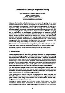
ing AR animations. One of these challenges is incorrect occlusion. Incorrect occlusion occurs when a real object blocks the user’s view of a virtual object. Typically, in AR visualization, the real world serves as the background of the scene and it has to be “drawn” before the computer generated contents are added to the foreground. As a result, although a real object may be closer to the observer, it can be visually blocked by a CAD object that is intended to be farther away. The primary reason for this visual discrepancy is that there is no established method in AR to obtain and consider the depth of real objects and as a result, incorrect occlusion can not be automatically handled. 2 Importance of Occlusion Handling in AR In an AR animated scene of a dynamic environment such as a construction operation, incorrect occlusion can occur very frequently and unexpectedly due to the fact that real and virtual objects (e.g. personnel, equipment, and material) can move freely with no constraints. When observing the animated construction operation of an earthmoving simulation, for example, incorrect occlusion can happen if a real excavator moves in front of a virtual model of a hauler. Under such condition, the virtual hauler has to be partially or completely invisible to the observer of the scene. Figure 1 shows a snapshot of an AR animation in which a virtual CAD model of an excavator is superimposed on the real scenes of the jobsite. In this Figure, two real objects (i.e. light pole, and the real excavator) are closer to the viewpoint and hence have to partially block the virtual excavator at two spots (i.e. stick and shovel). However, the observer of the scene sees the incorrect snapshot shown in (a) as opposed to the visually corrected view shown in (b) because incorrect occlusion can not be automatically handled unless appropriate methods are designed and integrated into the AR application.
(a)
(b)
Fig. 1. Example of occlusion in an AR scene of a simulated construction operation: (a) incorrect occlusion, (b) corrected occlusion.
When using a Head Mounted Display (HMD) to observe the augmented scene (e.g. in this research), the display surface is always between the eye and real objects and virtual objects always occlude real objects. As a result, additional steps are required to handle cases in which real objects must occlude virtual CAD objects (Breen et al 1995). The method presented in this paper uses depth and frame buffer manipulation techniques to automatically resolve incorrect visual occlusion. The presented approach is unique because it can be easily integrated into mobile AR platforms such as that developed by Behzadan et al (2008) which allows the observer of an AR animation to walk freely in the scene and observe the ongoing operations 25
Intelligent Computing in Engineering - ICE08
from any vantage position. The presented method is scalable to advances in sensing hardware and thus has significant potential to correctly resolve occlusion effects in AR animations in real time and at acceptable frame rates. 3 Previous Work in Occlusion Handling During the past few years and with the introduction of AR in engineering domains, a number of researchers have demonstrated algorithms and methods to handle incorrect occlusion in AR. For example, Breen et al (1995) presented techniques for interactively performing occlusion and collision detection between static real objects and dynamic virtual objects in AR. They used computer vision algorithms to acquire data that model aspects of the real world in form of geometric models and depth maps. Lepetit and Berger (2000) introduced a semiautomatic approach to solve occlusion in AR systems. Using their approach, once the occluding objects have been segmented by hand in selected views called key frames, the occluding boundary is computed automatically in the intermediate views. In order to do that, the 3D reconstruction of the occluding boundary is achieved from the outlined silhouettes. Fischer et al (2003) presented an algorithm based on a graphical model of static backgrounds in the natural surroundings, which has to be acquired beforehand. This algorithm is unable to deliver actual depth information for the scene. As a result, the main assumption was that whenever a real occluder is detected in front of the background, it is in front of all virtual objects. Hence, their method is primarily suitable for interaction with the AR scenes using hands or pointing devices, which can mostly be assumed to be closer to the user than virtual objects. Feng et al (2006) designed an optical-based algorithm to realize multilayer occlusion in indoor areas with objects only a few meters away from the viewer. The result of their work, however, caused unstable scenes as the process of object extraction was very sensitive to the change of ambient light illumination of the environment. Wloka and Anderson (1995) presented a video see-through AR system capable of resolving occlusion between real and computer generated objects. The crux of their system was an algorithm that assigns depth values to each pixel in a pair of stereo video images in near real time. However, the use of stereo cameras caused their method to have difficulties in computing the depth for featureless (evenly lit, non-textured, and horizontal) rectangular image areas. Most work conducted in occlusion handling thus far, does not take into account the dynamics of the real world in which an AR animation takes place. While some of them use simplifying assumptions about the position of the real objects and the viewpoint from which the scene is observed, several others use techniques that are most suitable for indoor controlled environments. For example, while the application of stereo cameras is an attractive option for real world depth acquisition, the result is very much dependent on the nature of the objects, their physical characteristics and appearance, and distances they are located from the observer of the scene. 4 Real Time Depth Acquisition Algorithm Design As described in Section 2, obtaining depth values for both real and virtual objects is the most important step in handling incorrect occlusion in AR. An intuitive approach to calculate the 26
Intelligent Computing in Engineering - ICE08
depth of a virtual CAD object in the scene is to extract its relative position to the observer of the scene at each animation frame since this piece of information is always maintained and updated by the graphical engine of the AR application (e.g. OpenGL). The depth values for real objects, however, have to be acquired and recorded using more complex methods as this group of objects are not interpretably modeled in the computer. In fact, the computer knowledge of a real scene is limited to the plain video captured by the video camera without any depth information. The level of detail according to which the depth of real and virtual objects is determined depends on the characteristics of the environment the operation takes place in and also the nature of the objects in the scene. For a scene consisting of only a few simple geometrical primitives, measuring the depth values at the object level seems to provide satisfactory results. However, to take into account all uncertainties involved in the way the real world is set up and avoid any unexpected depth miscalculation and paradox, a pixel level of detail was finally selected in this research. Following this approach, after the depth values for all real and virtual objects are obtained, the last step is to make a comparison at the pixel level to decide which object is closer to the user’s eyes and hence has to be painted last. Using this approach, for a specific pixel on the screen, if the value of the real world depth is less than that of the virtual world a real object is occluding a virtual object. Further steps are then taken in order to update the color scheme of that pixel so it is not painted in the color of the virtual object. Figure 2 shows the depth acquisition of real and virtual objects. The specific pixel on the screen shown in this Figure represents portions of a real tree and a virtual CAD model of an excavator. The depth of this pixel in the real world is captured using methods that will be described later in this paper. The depth value for the same pixel in virtual world can be obtained using transformation matrices and geometric properties of the CAD model represented by the pixel.
Fig. 2. Capturing the depth of real and virtual objects inside the user’s visible viewing frustum. 27
Intelligent Computing in Engineering - ICE08
Figure 3 illustrates the result of depth comparison performed at pixel level to determine whether or not the CAD object is occluded in the augmented view. This process has to be done continuously by capturing the latest real and virtual depth values for all the pixels on the screen. Depth values of the real world can change if the viewpoint is moved (i.e. user changes position and/or head orientation) or there is a change in the contents of the real scene. Depth values of the virtual world can also change if CAD objects move in the scene. By constantly comparing these two sets of values the depth effect can be included and represented in the augmented world to handle incorrect occlusion cases.
Fig. 3. Final AR screen with correct occlusion effect.
5 Augmented Reality Hardware Selection Producing correct occlusion effects in real time in an outdoor unprepared environment such as a construction site was a main design consideration in developing the automated occlusion handling method in this research. The authors have successfully designed, implemented, and presented a mobile computing apparatus called UM-AR-GPS-ROVER equipped with components necessary to perform a walk-through AR animation in real time (Behzadan and Kamat 2006, Behzadan et al 2008). As shown in Figure 4, the designed apparatus takes advantage of real time positioning data coming through the Global Positioning System (GPS) receiver as well as 3D head orientation data supplied by the head tracker device (inside the hard hat) to position the user inside the AR animation.
28
Intelligent Computing in Engineering - ICE08
Fig. 4. Profile of a user equipped with the mobile computing apparatus designed in this research.
In the apparatus shown in Figure 4, the main computing task is performed in a laptop computer secured inside the backpack. While the real scene is captured by a video camera in front of the user’s eyes, the rendered graphical scene is displayed to the user through the HMD installed in front of the hard hat. At the same time, the user can interact with the system using a miniature keyboard and a touchpad (Behzadan et al 2008). While the resulting AR animation has to be convincing enough to the observer of the scene, no additional constraint over the user’s maneuvering ability as well as position and orientation of both real and virtual groups of objects has to be created in the AR application. In addition, the required hardware components to perform the task of occlusion handling has to be selected in a way that they do not limit the mobility of the AR platform due to factors such as heavy weight, dependence on ground power source, special care and maintenance, and user’s ergonomics. As mentioned earlier, depth acquisition at pixel level of detail has the advantage that the scene can be arbitrarily complex, while the processing time remains a constant time function of image resolution. Additionally, no geometric model of the real environment is needed during the animation. However, the depth map is dependent on the user’s position and head orientation, as well as the location of real objects in the scene. Once the user or the real objects change their position and/or orientation, the depth map becomes invalid. In order to take into account all such variations, the process of depth acquisition and comparison has to be done in real time. As a result, developing methods to sense and prototype objects of the real world was a significant step in this research. The hardware component required to perform depth acquisition had to be selected in a way that it could be easily integrated into any existing mobile AR platform. Hence, being lightweight and self-powered, having a convenient interface and acceptable pixel resolution were among the important factors in selecting the hardware component. There was certainly a trade off between equipment mobility and data resolution. The larger and more powerful a camera is, the more data sample points it can collect and the resulting image is more accurate. This directly translates into more processing time which was not desirable for the purpose of this research as all calculations had to be performed in real 29
Intelligent Computing in Engineering - ICE08
time. Lighter cameras, although providing lower resolution depth images, can operate at a faster processing speed and hence are better fits for the AR platform explored in this research. Several product studies were performed on high resolution cameras such as 3DLS (7 to 8 kg), Konica Vivid 9i (15 kg), I-Site 4400 LR (14 kg), FARO LS 420 (14.5 kg), and Leica HDS 3000 (17 kg). Although all these cameras provide full range data (wide horizontal and vertical scanning angles) they could not be mounted on a mobile platform, primarily due to their weight and dependence on external power sources. In addition, according to most manufacturers, fixed tripods had to be used as mounting base in order to achieve best performance. Another category of imaging cameras is light weight cameras such as Laser Detection and Ranging Camera (LADAR) devices typically suitable for low range applications. This class of cameras uses a promising technology to provide robust and accurate access to depth data of real objects and has already proven to provide satisfactory results in similar research projects (Teizer et al 2007, Teizer et al 2005). Considering all these parameters, the final decision was made to develop a depth-based occlusion handling algorithm which uses real world depth map input coming through a remote sensing LADAR device connected alongside the video camera. The main advantages of LADAR devices are their light weight, high data resolution, and ability to extract depth data in almost any environment type including outdoor construction sites. The limitations are constant noise in the incoming data, and limited operational range (in average less than 10 meters). However, the occlusion handling method introduced in the presented research has been designed as generic as possible so that future products with higher levels of accuracy and wider operational range can be easily plugged and used in the AR platform without any modifications or changes necessary to the core algorithms. 6 Implementation A flash LADAR system typically consists of a device constantly casting laser beams in the 3D real space and receiving the resulting reflected beams. Based on the travel time for each beam and knowing the speed of the laser beam, the distance between the flash LADAR system and each real object in the scene is calculated. Once installed in front of the user’s eyes, these depth values reflect the distance between the viewpoint and the real objects. Flash LADAR data represent a scene as a matrix. Each element in this matrix contains depth value of the corresponding pixel on the screen. As a result, the concept of screen matrix was introduced and used in this research to provide a means to store and retrieve depth values more efficiently inside the AR platform. By definition, a screen matrix is a 2D matrix with dimensions equal to the pixel resolution of the screen. Each element in this matrix can hold data (e.g. RGB color, depth value) about the corresponding pixel on the screen. Figure 5 shows a sample depth matrix for a 640x480 screen.
30
Intelligent Computing in Engineering - ICE08
Fig. 5. Sample screen matrix for a 640 by 480 screen.
Depth values for the pixels on the virtual screen are also retrieved from the OpenGL z-buffer. Z-buffer is in fact a memory buffer in the OpenGL graphics accelerator that holds the latest depth of each pixel along the Z axis. As the virtual contents of the scene change over time, the values stored in the z-buffer are also updated to reflect the latest depth of the CAD objects relative to the user’s eyes (Yu 2004). The fundamental difference between depth values obtained from a flash LADAR camera for real objects and those obtained from z-buffer for virtual objects is that while real world depth values are retrieved and reported as real distances (in terms of meters or feet) to the user, depth values for the virtual CAD objects fall between a [0,1] interval. A pixel located on the near plane of the perspective viewing frustum will be given a depth value equal to zero and a pixel located on the far plane of the perspective viewing frustum will be given a depth value equal to one. All intermediate pixels will have depth values between zero and one. However, the relationship between the depth values obtained from the z-buffer and corresponding metric depth values is not linear. In other words, a pixel with a virtual depth value of 0.5 is not located halfway between the near and far planes. In fact, this relationship, as shown in Figure 6, follows a hyperbolic equation.
31
Intelligent Computing in Engineering - ICE08 Fig. 6. Relationship between z-buffer and metric virtual depth values.
In this Figure, Znear and Zfar correspond to the metric distance between the user’s eyes and the near and far planes of the perspective viewing frustum respectively. Zbuffer is the depth value of a specific pixel on the screen obtained from the z-buffer and Zreal is the metric equivalent of this depth value for the same pixel. As shown in this Figure, z-buffer has higher resolution for pixels closer to the user’s eyes. In fact, for the specific case shown in Figure 6, more than 90% of incoming values through the z-buffer represent depth of objects located 10% the distance between the near and far planes. Depth values for the virtual objects are also stored in a separate screen matrix for later comparison with corresponding values of the real world. After all depth values are obtained and stored appropriately in separate screen matrices, they have to be compared so that for each pixel, a final decision can be made on which group of objects (real or virtual) is closer and hence has to be displayed. Once this decision is made, the color of the pixel can be changed to the color of the object closer to the viewpoint to create the impression that the pixel really represents the correct object. This requires an intermediate step which is obtaining the color values (in terms of RGB) for each individual pixel on the screen. This can be done directly by reading the OpenGL color buffer which stores pixel color values in real time. Figure 7 shows the frame buffer manipulation algorithm designed in this research. This algorithm uses four matrices in order to construct a final screen matrix (i.e. matrix E in this Figure): A: Screen matrix of real world color values (obtained from OpenGL color buffer), B: Screen matrix of real world depth values (obtained from a remote sensing device such as a LADAR camera), C: Screen matrix of color values of CAD models (obtained from OpenGL color buffer), and D: Screen matrix of depth values of CAD models (obtained from OpenGL depth buffer). Screen matrix E, as used in Figure 7, contains correct pixel colors after resolving all incorrect occlusion cases. In this Figure, for every pixel on the screen, the corresponding color and depth values are read from the four matrices A, B, C, and D defined above. The real and virtual depth values are then compared. If the depth of the pixel in the real world is less than its depth in the virtual world, its color is changed to the color read from the matrix representing real world colors (i.e. matrix A). This represents the case in which a real object is occluding a virtual object. The other scenario occurs when the depth of the pixel in the virtual world is less than its depth in the real world. This represents the case in which a virtual object is occluding a real object and hence its color is changed to the color read from the matrix representing virtual world colors (i.e. matrix C). The correct pixel color (shown as e in Figure 7) is then stored in screen matrix E that will be used later when the OpenGL frame buffer is updated to visually show the correct occlusion effect.
32
Intelligent Computing in Engineering - ICE08
Fig. 7. Designed frame buffer manipulation algorithm.
7 Validation of Results The ability of the presented occlusion handling method to perform real time depth analysis and correct occlusion effects between real and virtual objects was validated inside an AR visualization application called ARVISCOPE previously designed by the authors. ARVISCOPE is capable of generating AR animations of simulated engineering operations from the results of running simulation models of the same operations (Behzadan and Kamat 2007a). A number of small scale experiments using various engineering operational scenarios were conducted to create animations with correct occlusion effects in indoor environments. Since the main focus of these experiments was to validate the effectiveness of the proposed occlusion handling algorithm, the depth data of real objects (screen matrix B in Figure 7) were assumed to be known to the AR application at the beginning of the animation. The objective was to validate that, given the depth map of the real world in view, the designed algorithm is capable of detecting and correcting visual occlusion effects in real time and produce visually convincing AR animations representing the engineering operation (Behzadan 2008). Figure 8 shows results of an indoor proof-of-concept experiment conducted in ARVISCOPE in which CAD models of a backhoe excavator and a dozer were superimposed on a small scale construction environment consisting of a real tower crane and a real dump truck. The virtual dozer was 33
Intelligent Computing in Engineering - ICE08
partially occluded by the real tower crane and this was correctly detected and handled as shown in this Figure.
Fig. 8. Sample occlusion handling experiment in an indoor environment.
8 Summary and Conclusions The application of AR in animating simulated construction operations has significant potential in reducing the model engineering and data collection tasks, and at the same time can lead to visually convincing output. As a tradeoff, however, the animation has to be capable of handling two distinct groups of objects: virtual and real. This is very essential in AR as the observer of the animation expects to see a mixed scene of seamlessly merged real and virtual objects in which both groups of objects operate and interact in a realistic manner. This introduces a number of challenges unique to creating AR animations. One of these challenges is resolving incorrect visual occlusion effects. Incorrect occlusion occurs when a real object blocks the observer’s view of a virtual object. In a dynamic scene such as a construction operation, incorrect occlusion can occur very frequently and unexpectedly because the real and virtual resources and personnel can move freely with no constraints. In this paper, an automated pixel-level occlusion handling method designed by the authors was introduced and described. A number of indoor tests have proved the effectiveness of the presented method in AR animations of dynamic operations. This was a critical step of the project since achieving successful results in an indoor controlled environment helps validate the functionality of the proposed algorithm before applying it to situations in which engineering operations take place in larger, more dynamic environments where there is less control over the motion of real and virtual objects. In order to ensure that the results of this project can be applied to real life engineering problems, the next step will be to conduct large scale visualization experiments of engineering operations in outdoor uncontrolled environments such as a real construction site or a manufacturing plant. At this stage, appropriate remote sensing devices will be integrated into the AR application to facilitate the task of real time on-site depth acquisition. More complex scenarios will then be tested to make sure that the presented occlusion handling technique can achieve successful and reliable results in common engineering environments.
34
Intelligent Computing in Engineering - ICE08
9 Acknowledgments The presented work has been supported by the United States National Science Foundation (NSF) through grant CMS-0448762. The authors gratefully acknowledge NSF’s support. Any opinions, findings, conclusions, and recommendations expressed by the authors in this paper do not necessarily reflect the views of NSF. References Barnes, M.R. (1997) “An Introduction to QUEST.” Proc. of Winter Simulation Conference (WSC97), Atlanta, GA, USA. Behzadan, A.H. (2008) “ARVISCOPE: Georeferenced Visualization of Dynamic Construction Processes in Three Dimensional Outdoor Augmented Reality.” Ph.D. Dissertation, Ann Arbor, University of Michigan, MI, USA. Behzadan, A.H. and Kamat, V.R. (2007a) “Enabling Smooth and Scalable Dynamic 3D Visualization of Discrete-Event Construction Simulations in Outdoor Augmented Reality.” Proc. of Winter Simulation Conference (WSC07), Washington, DC, USA. Behzadan, A.H. and Kamat V.R. (2007b). “Georeferenced Registration of Construction Graphics in Mobile Outdoor Augmented Reality.” ASCE Journal of Computing in Civil Engineering Vol. 21, No. 4, pp. 247-258. Behzadan, A.H. and Kamat, V.R. (2006) “Animation of Construction Activities in Outdoor Augmented Reality.” Proc of the 11th Joint International Conference on Computing and Decision Making in Civil and Building Engineering (ICCCBE-XI), Montreal, Canada. Behzadan, A.H., Timm, B.W., and Kamat, V.R. (2008). “General Purpose Modular Hardware and Software Framework for Mobile Outdoor Augmented Reality Applications in Engineering.” Elsevier Journal of Advanced Engineering Informatics, Volume 22, No. 1, pp. 90-105. Bishop, J.L., and Balci, O (1990) “General Purpose Visual Simulation System: A Functional Description.” Proc. of Winter Simulation Conference (WSC90), New Orleans, LA, USA. Breen, D.E., Rose, E., and Whitaker, R.T. (1995), Interactive Occlusion and Collision of Real and Virtual Objects in Augmented Reality. Technical report ECRC-95-02, European Computer-Industry Research Center, 1995. Feng, Y., Du, W., Guan, X., Gao, F, and Chen, Y (2006) “Realization of Multilayer Occlusion between Real and Virtual Scenes in Augmented Reality.” Proc of the 10th International Conference on Computer Supported Cooperative Work in Design, Nanjing, China. Fischer, J., Regenbrecht, H., and Baratoff, G. (2003), “Detecting Dynamic Occlusion in Front of Static Backgrounds for AR Scenes.” Proc of the Workshop on Virtual Environments, Zurich, Switzerland. Fuhrmann, A., Hesina, G., Faure, F., Gervautz, M. (1999). “Occlusion in Collaborative Augmented Environments.” Elsevier Journal of Computers and Graphics, Vol. 23, No. 6, pp. 809-819. Kamat, V.R., and Martinez, J.C. (2003). “Automated Generation of Dynamic Operations Level Virtual Construction Scenarios.” Electronic Journal of Information Technology in Construction (ITcon), Volume 8, pp. 6584. Lepetit, V. and Berger, M.O. (2000). “A Semi-Automatic Method for Resolving Occlusion in Augmented Reality.” Proc. of IEEE Conference on Computer Vision and Pattern Recognition, Hilton Head Island, SC, USA. Rohrer, M.W., and McGregor, I.W. (2002) “Simulating Reality Using AUTOMOD.” Proc. of Winter Simulation Conference (WSC02), San Diego, CA, USA. Teizer, J., Caldas, C.H., and Haas, C. (2007). “Real-time Three-Dimensional Occupancy Grid Modeling for the Detection and Tracking of Construction Resources.” ASCE Journal of Construction Engineering and Management, Volume 133, No. 11, pp. 880-888. Teizer, J., Liapi, K., Caldas, C.H., and Haas, C. (2005). “Experiments in Real-Time Spatial Data Acquisition for Obstacle Detection.” Proc. of the Construction Research Congress, San Diego, CA, USA. Wloka, M.M., and Anderson, B.G. (1995) “Resolving Occlusion in Augmented Reality.” Proc. of the Symposium on Interactive 3D Graphics, Monterey CA. Yu, T. (2004). “Depth of Field Implementation with OpenGL.” Journal of Computing Sciences in Colleges, Volume 20, No. 1, pp. 136-146. 35