RECONFIGURATION APPROACH OF VECTOR CONTROL SYSTEM FOR TANDEM CONVERTER FED INDUCTION MOTOR DRIVE József Vásárhelyi*, Mária Imecs**, Ioan Iov Incze**, Csaba Szabó** * University of Miskolc, H3530 Miskolc, Egyetemváros,
[email protected] **Technical University of Cluj, P.O. Box 99, RO-3400 Cluj-Napoca, Tel/Fax: 40-64-194924,
[email protected],
[email protected],
[email protected]
ABSTRACT: This paper presents the research results regarding to the reconfiguration aspects of AC drive control system realised with induction motor supplied from the so-called “tandem” converter in order to use CSoC and FPGA reconfigurable hardware for its implementation. Reconfiguration hardware support is critical and for this reason some implementation and simulation results are presented.
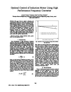
Keywords: embedded control, system reconfiguration, vector control 1. INTRODUCTION There are different approaches to define the reconfigurable systems. One of them is presented by VCC Corporation [9], which describe reconfigurable computing technology an ability to modify in real time the hardware architecture of a computer system. In this approach reconfigurable computing is also often called „Custom” or „Adaptive”. Reconfigurable systems are computing platforms, to which the software to suit the application at hand modifies the architecture [8]. That means, within the application program a software routine exists, which downloads a digital design directly into the reconfigurable space of the system. Field Programmable Gate Arrays (FPGAs) are widely used in digital signal processing. In some applications, they perform even better then the DSPs. An alternative solution for the multiple-controller implementation is presented in this paper, using the Triscend’s Configurable System on a Chip (CSoC). The necessity of reconfiguration is based upon the practical observations that the performances of various types of vector-controlled drives are different, depending on the range of speed, mechanical load characteristics, and the type of the supply power electronic converter. It is known that the rotor flux oriented vector control is widely used. 2. TANDEM CONVERTER FED INDUCTION MOTOR The “tandem” configuration is a new solution of DC link Static Frequency Converters (SFC) for medium- and high-power AC drives [5][6]. It combines the advantages of the current- and voltage-source inverters. The two inverters of different power range work in parallel arrangement. A larger current-source inverter (CSI) converts the real power, while a smaller voltage-source inverter (VSI) supplies the reactive power required to improve the quality of the load currents. In Figure 1 the induction motor is supplied from a three-phase tandem converter. The large-power primary inverter (CSI) is realized with GTO thyristors and operates in Pulse Amplitude Modulation (PAM) mode. It is fed with filtered DC-link current, given by a phase-controlled rectifier, which can realize the bi-directional energy flow, too.
AC line
i sRef
π 2 3 R ef
i Ref DC
+
-
VA1 ε s Synchronisation
ωRef r
α iDC fs
SFC with PAMCSI
SFC with PWMVSI VA3
Figure 1. Stator-field-oriented vector control system for the tandem inverter-fed induction motor.
The low-power secondary inverter (PWM-VSI) usually is realized with IGBTs and it works in Pulse-Width Modulation (PWM) mode. Its DC link is fed from a diode rectifier, which is incapable of reversed power flow. In this DC link the VSI input voltage is filtered by means of a large capacity condenser. 3. CONTROL OF THE TANDEM CONVERTER The tandem converter needs different control strategies depending on the component converters, which are actually working, and on the type of the PWM procedure used for the VSI. The open-loop voltage-control PWM procedures, i.e. carrier-wave or Space-Vector modulation (SVM), keeps the voltage source of the VSI, but using closed-loop current-control PWM procedures (e.g. the common bang-bang current control) the behaviour of the VSI becomes of current source character [1], [3]. If the VSI fails, then the control system structure needs to be reconfigured in order to continue its “mission”. The VSI, which failed is decoupled from the motor terminals and there will be connected 3 current filtering condensers. The new control scheme presented in Figure 2, is applied after reconfiguration. It is much simpler due to the fact the CSI is directly controlled with current variables. The field identification in the first step is made in the same way, by integration of the stator-voltage equations (using computation block ΨsC), which gives the stator-flux natural dq components. This part also needs reconfiguration because in Figure 2 the stator-voltage can be measured directly due to the PAM operation mode of the CSI, instead to be computed it, as is made in Figure 1 in PWM operation mode. Furthermore, in rotor-field orientation it is necessary to compensate the stator-field components in block ΨmCo and ΨrCo in order to obtain the air gap and then the orientation ones. The current reference variables ims and isqλs obtained from the flux and torque controllers will generate the field-oriented voltage reference values vsdλr and vsqλr using the computation block VsC, as follows:
AC line
i Ref DC
π
DC-link current controller -
2 3
is Flux Controller
ΨrRef
ω rRef +
-
m eRef+
+
-
Ref i sd λr
Torque Controller
Ref i sq
[D(-λ r )]
-
iD C
Ref
Ld
Diode Rectifier
CSI Current
ε sRef
Ref i sd
CooT
Ref i sq λr
Phase Controlled Rectifier
α
+
VA 1
Synchronisation
fs ε C SI
CSI
cos λ r sin λ r PW M VSI
i sd λ r
i sd i sq
CooT
m eC
[D(λ r )]
v sd v sq
Indentified Field
Ψr
ωr
Ψ sd VA
ψ r Co
Ψ m Co
Air-gap-flux compensation
Stator-flux comutation
ψ sq
ψ sC
PhT [A]
[i s ]
PhT [A]
[u s]
Phase Transformation
3xC
Induction motor
M echanical Angular Speed Rotor-flux compensation
Figure 2 Rotor-field-oriented vector control system for current-source inverter-fed induction motor. Ref τ s dims ) 1 + σ s dt τs Ref ω λs ims ) + 1+ σ s
v Ref sdλs = R s (i sdλs +
(1)
Ref Ref v sq λs = R s (i sqλs
(2)
Due to the computed stator-voltage reference variables, this scheme also offers the simplest identification of the orientation field, based on the integration of the stator-voltage equation. 4. RECONFIGURABLE CONTROL SYSTEM
The reconfigurable control system concept was introduced in [2] and analysed in [3]. The reconfigurable control system is derived from reconfigurable system concept. In this concept the same hardware support, which implements one control system structure, can be used also to switch to another control system scheme. Each control system structure can be seen as a distinct state of a logic state machine [7]. The transitions from one logic state, i.e. one control system structure (one hardware configuration), can be determined by the value of the state variables of the controlled system. If a transition condition occurs, (i.e. the VSI fails) the need for reconfiguration is fulfilled. The control system will start a self-reconfiguration process and will change the control system structure configuration automatically. The basic structures of the reconfigurable control system are presented in Figure 1 and Figure 2. On the presented vector control scheme in Figure 1, if the VSI fails, then the control system structure needs to be reconfigured in order to continue its “mission”. The control structure, which is applied after reconfiguration it is represented in Figure 2. The control of the execution element, represented by the AC motor together with the PWM and the electrical and mechanical sensors assembly, impose real-time performance of the control system algorithm. One may conclude that decreasing the sampling period the control system can perform better. On the other hand decreasing the sampling period this can impose very short reconfiguration time, which technologically is impossible yet. The sampling period have to accomplish the following criterion:
Considering that the AC motor should not be left without control, the reconfiguration time have to be less equal then the sampling period of the control system: (3) treconfiguration < Tsampling The problem it is solved not only by choosing corresponding hardware structures (chips) with high reconfiguration frequencies. The time constraints depend also on the hardware and reconfiguration method used. Reconfiguration can be done in several ways, depending on the hardware resources used in the implementation. Depending on the implementation hardware (FPGA or CsoC) the reconfiguration can be done as: partial or total reconfiguration. Partial reconfiguration – reconfiguring each module step by step conform to the method introduced in[4]. The method is called pipeline morphing, and is intended to reduce the latency involved in reconfiguring from one pipeline to another. The basic idea is to overlap vector control computation and reconfiguration of the control system. The first few pipeline stages are being reconfigured to implement new functions so that data can start flowing into the newly configured stages of the pipeline, while the rest of the pipeline stages are completing the current computation. Instead of changing the entire pipeline at once, the method involves morphing one pipeline to another (one control system structure to another). For this strategy there is an obvious method for reconfiguring an n stage pipeline and involves three steps [4]: • First, one needs to complete the current computation and clear the pipeline, which takes n cycles. • Then reconfiguration can take place. • Finally one has to wait for n cycles for the result to flow through the newly configured pipeline. The third step is not applicable for control systems as the characteristic of the process do not allow n sampling period cycles to leave the drive without control (open loop control). The pipeline morphing reconfiguration method means for the tandem control system, that each module computes its function, and then it is reconfigured and then computes its new function. These 3 steps, mentioned before, which are similar to those, mentioned by Luk, but the entire control system configuration has to be done during one sampling period (Tsampling) The result of the reconfiguration must not affect the control of the drive. There is another aspect, which was not treated yet and it should be from the point of view of the control system. The pipeline morphing reconfiguration algorithm was treated for computing structures, which changes not only the algorithm but also the data to be processed. For the control system, it is very important to consider the parameter transfer from one control structure to the new reconfigured one. The structure presented in [4] suffers some modifications in order to introduce parameter transfer registers (PTR), which will store the parameters, in order to transfer them from one control structure to the other. PTR
F1
PTR
F2
PT R
F3
PTR
G1
PTR
F2
PT R
F3
PTR
G1
PTR
G2
PT R
F3
PTR
G1
PTR
G2
PT R
G3
Figure 3. Pipeline morphing process with parameter transfer registers.
We conclude: in the case of reconfigurable control systems parameter transfer have to be independent form the chosen reconfiguration method. This is important not only from the technical point of view but also from the financial aspect of the question as it is connected to the hardware used (number and type of chips).
The control system presents modularity and this is based upon the observation that most of the modules of the control system execute the operation multiply-add-or subtract. In Figure 4 it is shown a part of the hardware structure implemented the mentioned structure. 5. SIMULATION RESULTS AND CONCLUSIONS
The simulation was performed in MATLAB Simulink environment. The induction motor data are: 5.5kW, 50Hz, 220Vr.m.s., 14Ar.m.s. and 4 pole-pairs. The simulation was made for the induction motor fed by the tandem converter where the VSI is working with open-loop voltage PWM procedure and the CSI is synchronised with the stator currents. The VSI operates with variable modulation index and it is fed by 530V DC-link voltage. The DC-link current of the CSI (corresponding to PAM procedure) is controlled in closed loop procedure as is presented in Figure 1 and 2. It shows the starting of the no-loaded motor and then the motor behaviour in the case of suddenly loading.
Figure 4. Triscend’s CSoC software environment with implemented parts of the reconfigurable control system.
The simulation results show that the tandem converter produces an improved output current waveform due to the PWM procedure of the VSI inverter. Considering a PWM-VSI equivalent in power to the whole tandem converter and comparing it with the secondary VSI from the tandem, the ratio of the average absolute values of output currents in these converters would be 3,7. This indicates that the PWM switching losses will be considerable reduced in the case of tandem operation because a considerable part of the energy flowing through the CSI is no more width modulated. Experimental results are also presented in [5], [6]. If PWM-VSI fails, it is disconnected from the motor terminals and the structure of the vector control system is reconfigured according to the new character of the actuator (now i.e. CSI) in order to be able to continue the drive to work. Consequently, using reconfiguration of the control system can be increased the Mean-Time Between Failure (MTBF) of the tandem converter fed induction motor drive.
a) Stator current space phasor
b) iVSI space phasor
Figure 5. Current space phasors
a ) i m , iC S I, i V SI
b ) M e c h a n ic a l c h a ra c t e ris t ic s
Figure 6. Currents and mechanical characteristics
The CSoC allows in a single chip to process data in either hardware or software algorithm, which results in a faster processing time. One can conclude that this processing time will influence also the decreasing of the sampling period in vector control. Beside of the sampling period variation, the changes in control law and control system structure due to reconfiguration may improve the performance of the controlled system and also adaptive control can be avoided. 6. REFERENCES [1] IMECS Maria: Open-Loop Voltage-Controlled PWM Procedures, ELECTROMOTION’99, Patras, Greece, Vol. I, pp. 285-290. [2] IMECS Maria: Synthesis About Pulse Modulation Methods in Electrical Drives – Part 1 and Part 2 CNAE’98 Craiova, Romania, pp. 19-33. [3] IMECS Maria: Synthesis About Pulse Modulation Methods in Electrical Drives – Part 3, Acta Universitas CIBIENSIS, Vol. XVI Technical series, H. Electrical Engineering and Electronics, “Lucian Blaga” Univ. of Sibiu, Romania, 1999, pp. 15-26. [4] LUK W., SHIRAZI N., CHEUNG P., Modelling and Optimising Run-time Reconfigurable Systems, Proceedings FCCM96, IEEE Computer Society Press, 1996 [5] MACIEJOWSKI J. M.: Reconfigurable Control Using Constrained Optimisation, Proceeding of European Control Conference ECC97, Brussels, Belgium, 1997 pp. 107-130. [6] TRZYNADLOWSKI A. M, BLAABJERG F., PEDERSEN J. K., PATRICIU A., PATRICIU Niculina, A Tandem Inverter for High Performance AC Drives, Conf. Rec. IEEE-IAS Annual Meeting, St. Louis, Missouri, USA, October 1998, pp. 500-505 [7] VÁSÁRHELYI J., IMECS Maria, INCZE J. J, Run-time Reconfiguration of Tandem Inverter used in Induction Motor Drives, Proceedings of Symposium on Intelligent Systems in Control and Measurement, Veszprém, Hungary, 2000, pp. 138-143. [8] VUILLEMIN J., BERTIN P., RONCIN D., SHAND M., TOUATI H., BOUCARD P., Programmable Active Memories: Re-configurable Systems Come of Age', IEEE Trans. on VLSI Systems, Vol. 4, No. 1, March, 1996, pp. 56-69, [9] x x x: http:\\www.vcc.com: What is Reconfigurable Computing? Virtual Computer Corporation, 1999