Multipath Ultrasonic Gas Flow Meter
Flow Calibration Procedure Procedure Manual PRD-0000022557 / Rev. 00G / FL / nb / October 2009
The Most Trusted Name In Measurement
MNKS013 0.1 (10/09)
MPU Flow Calibration Procedure
History Revision Rev. 01 / B
Date 31.01.2008
Editor
ECN
xx
20143
Status released
Take over from KOS SAP System
Description
released
New Logo
Rev. 00C
April 2008
NB
20207
Rev. 00D
September 2008
IC
20384
released
Technical description of Force calibration Facility.
00E
February 2009
Thk
20512
Released
New first and last page
Rev. F
October 2009
FRL
20756
released
Test set up modified
Rev. G
October 2009
NB
20767
released
Average flow deviation delete
Important All information and technical specifications in this documentation have been carefully checked and compiled by the author. However, we cannot completely exclude the possibility of errors. Smith Meter GmbH is always grateful to be informed of any errors.
MPU Series B Ultrasonic Gas Flow Meter
TABLE OF CONTENT 1.
INTRODUCTION ..................................................................................... 4 1.1. Equipment Required ........................................................................... 4 1.2. References........................................................................................... 5 1.3. Warnings.............................................................................................. 5 1.4. Abbreviations ...................................................................................... 5 1.5. Responsibility ..................................................................................... 6 2. TEST SET-UP ......................................................................................... 8 2.1. In-House Testing ................................................................................. 8 2.2. Installation Arrangement .................................................................... 8 3. HARDWARE INSPECTION AND INSTALLATION............................... 10 4. INITIAL CHECKING .............................................................................. 12 5. FLOW TEST .......................................................................................... 14 5.1. Flow Test Description ....................................................................... 14 5.2. Flow Ranges ...................................................................................... 15 5.3. Flow Test Documentation ................................................................ 15 5.4. Post-Test Procedure ......................................................................... 15 6. ACCEPTANCE CRITERIA .................................................................... 16 6.1. Acceptance Criteria for the MPU (according to AGA–9)................ 16 6.1.1. Accuracy .................................................................................. 16 6.1.2. Repeatability – AGA 9 .............................................................. 17 6.1.3. Linearity - AGA9 ....................................................................... 17 6.1.4. Velocity of Sound - AGA9......................................................... 18 6.2. Acceptance Criteria for the MPU (according to NPD) .................... 19 6.2.1. Accuracy - NPD ........................................................................ 19 6.2.2. Repeatability - NPD .................................................................. 19 6.2.3. Linearity - NPD ......................................................................... 20 6.2.4. Uncertainty limit for the MPU - NPD ......................................... 20 7. PROJECT SPECIFIC INFORMATION .................................................. 21 7.1. Project Data ....................................................................................... 21 7.2. Meter Data.......................................................................................... 21 7.3. Calibration Data ................................................................................ 22 7.4. Flow Test Points ............................................................................... 23 7.5. Additional Equipment Data .............................................................. 24 8. FLOW TEST EVALUATION .................................................................. 25 9. CONCLUSION ...................................................................................... 27 10. APPENDIX ............................................................................................ 28
PRD-0000022557 Rev. 00G MNKS013 0.1 (10/09)
Page 3 of 32
MPU Flow Calibration Procedure
1. INTRODUCTION This document describes the flow test procedure of the MPU Series B ultrasonic gas flow meter. The ability of the meter to measure the correct gas flow rate, is the functional characteristic to be tested. There are limitations at the flow test facility regarding pressure and temperature variations. The conditions at the test facility may differ from the operational conditions, but the meter is zero-calibrated for both the test conditions and the operating conditions. The flow test result will be presented in a flow calibration certificate for each meter, issued by the flow test facility. The deviation between the measured gas volume flow and the reference measurement shall be within the required limits. If not, further investigation is needed.
1.1. Equipment Required ·
An MPU ultrasonic gas flow meter with zero-calibrated transducers.
·
If applicable; required upstream and downstream spools and/or Adapter Spools.
·
If applicable; flow conditioner
·
Required gaskets, bolts and nuts.
·
Cables and interface converters to be used between the meter and the safe area.
·
PC or laptop for logging of trendlog data, checking of signal quality, and calculation of correction factors.
·
Spare parts for the meters: Ø Electronic boards Ø Transducers Ø Transducer cables
·
Page 4 of 32
Tools to open the electronic box and to change the transducers.
PRD-0000022557 Rev. 00G MNKS013 0.1 (10/09)
MPU Series B Ultrasonic Gas Flow Meter
INTRODUCTION
1.2. References The following documents are referred to within this Test Procedure: 1
NPD-regulations
Regulations for fiscal measurement of oil and gas.
2
NPD-regulations
Regulations relating to measurement of petroleum for fiscal purposes and for calculation of CO2-tax (Måleforskriften / The measurement regulations). 1 November 2001.
3
NORSOK standard, I-104
Fiscal Measurement systems for hydrocarbon gas, Rev. 3, November 2005.
4
A.G.A. Report No. Measurement of Gas by Multipath Ultrasonic 9 Second Edition Meters April 2007
5
PRD-0000022555 Function Test Procedure, MPU Series B
6
PRD-0000022541 Product Identification, MPU Series B
7
USM-0000020565 User Manual, MPU Series B
1.3. Warnings Warning, gas under pressure! Never attempt to disconnect or connect a pressurized connection. Never apply power to the meter without permission from the test site operator.
1.4. Abbreviations Abbreviation Description AGA
American Gas Association
FAT
Factory Acceptance Test
HES
Health, Environment and Safety
MPU
MultiPath Ultrasonic
NPD
Norwegian Petroleum Directorate
PRD-0000022557 Rev. 00G MNKS013 0.1 (10/09)
Page 5 of 32
MPU Flow Calibration Procedure
Abbreviation Description PC
Personal Computer
STDEV
Standard Deviation
VOS
Velocity Of Sound
1.5. Responsibility The FMC representative is the test coordinator. The FMC representative will cooperate with the appointed test site operator and the Contractor in order to perform the flow test. NOTE: FMC is not liable for availability of gas flow or problems at the test site on the day of the calibration. If deviations from this procedure are required, this must be agreed upon first between the Contractor and FMC, second between the test site and FMC. All work is performed in accordance with relevant Health, Environment and Safety (HES) regulations. Relevant parts of FMC Kongsberg Metering HES manual and pressure test manual will be followed. FMC is responsible for all equipment delivered by FMC Kongsberg Metering, regarding both high pressure and hazardous area related aspects. The test site is responsible for their part of the test loop, regarding both high pressure and hazardous area related aspects. The test site is responsible for checking for gas leakage on all equipment, and to permit power to be switched on.
Page 6 of 32
PRD-0000022557 Rev. 00G MNKS013 0.1 (10/09)
MPU Series B Ultrasonic Gas Flow Meter
INTRODUCTION
This page is intentionally left blank
PRD-0000022557 Rev. 00G MNKS013 0.1 (10/09)
Page 7 of 32
MPU Flow Calibration Procedure
2. TEST SET-UP 2.1. In-House Testing In-house testing is performed prior to the flow test (FAT) according to PRD-0000022555 “Function Test Procedure, MPU Series B” [5]. Zero calibration is performed to determine transducer delays and tcorrections. Inner diameter and path lengths are accurately measured. Zero flow and velocity of sound is verified either with pressurized Nitrogen or air after flow meter parameter configuration.
2.2. Installation Arrangement A general installation arrangement is sketched below. The item numbers refer to table in chapter 7.5. Pressure Transmitter (Alt. 1) 7a Electronics Enclosure
Pressure Transmitter (Alt.2)
Optional Flow Conditioner
6
Temperature Transmitter
7b
8
Upstream Spool
G as F low
4
Optional Upstream Adapter Spool
2
M PU
1
Flange Connection
G as F low
3
5
Downstream Spool
Optional Downstream Adapter Spool
Figure 1 Installation Arrangement
Page 8 of 32
PRD-0000022557 Rev. 00G MNKS013 0.1 (10/09)
MPU Series B Ultrasonic Gas Flow Meter
TEST SET-UP
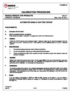
The Figure 2 below shows a typical block diagram of the test set-up for one MPU. Pressure and temperature readings will be done both at the location of the reference meter and at the location of the MPU. Flow measurements from the reference meter and of the MPU will be recorded simultaneously and compared to calculate the deviations.
Reference Measurement Computer Optional: Pulse input from MPU or RS485 input from MPU
PC with MPU WinScreen Ethernet/RS 485
Flow Pressure Temperature
Test Site Control Room
Electronics P
Site Inlet
Gas Flow
P
T
Reference Meter
Alt.1 Alt.2 T
MPU Meter
P
Downstream Spool
Flow Control Valve Site Outlet Gas Flow
Figure 2 Block diagram of the test set-up
PRD-0000022557 Rev. 00G MNKS013 0.1 (10/09)
Page 9 of 32
MPU Flow Calibration Procedure
3. HARDWARE INSPECTION AND INSTALLATION A. Check that there is no damage on the meter or piping from transportation. If this is the case, FMC Kongsberg must be notified immediately, and the damage must be documented and photographed. B. Check that pressure test certificates are available for the MPU and up- and downstream piping. C. Check the inner diameters at each end of the spools upstream and downstream of the MPU. Note the results in the table in Chapter 7.5. D. Install the MPU with corresponding pipes and, if applicable, flow straightener mechanically. The installation must be done in accordance with general procedures for the task. E. Install the cables between the meter and the control room in safe area and connect all wires. F. Check that the junction boxes are properly closed to prevent water intrusion. G. Check that reference instrumentation is properly installed. H. Place the PC for logging the MPU measurements in-house in safe area. I. Do not switch power on until cable installation and safety grounding is verified and allowance is given by the test site operator.
Page 10 of 32
PRD-0000022557 Rev. 00G MNKS013 0.1 (10/09)
MPU Series B Ultrasonic Gas Flow Meter
INITIAL CHECKING
This page is intentionally left blank
PRD-0000022557 Rev. 00G MNKS013 0.1 (10/09)
Page 11 of 32
MPU Flow Calibration Procedure
4. INITIAL CHECKING The initial checking is done for the MPU and must be performed by competent and qualified personnel. A. Verify cable installation and protective grounding. B. Before applying power to the pulse loop, check that the current through the pulse loop is limited by a resistor or internal circuitry in the reference system or flow computer. If in doubt, unplug the pulse output cable on the meter and measure the current through the loop with a multi-meter. If the current is higher than 10 mA, a resistor needs to be inserted in the loop (5kOhm). A high current through the pulse output will cause permanent damage to the UDSP board. C. Switch the power on. D. Establish contact with the PC and start the WinScreen-program. Check the signals for all paths. E. Perform flow system tests to verify that the MPU is working satisfactory.
Page 12 of 32
PRD-0000022557 Rev. 00G MNKS013 0.1 (10/09)
MPU Series B Ultrasonic Gas Flow Meter
INITIAL CHECKING
This page is intentionally left blank
PRD-0000022557 Rev. 00G MNKS013 0.1 (10/09)
Page 13 of 32
MPU Flow Calibration Procedure
5. FLOW TEST 5.1. Flow Test Description Project specific details for this flow test are given in Section 0. The flow meter shall be flow calibrated at an accredited gas flow calibration facility (See list of various facilities in Appendix 1). The test below is performed for a predefined set of flow velocities Each run has a fixed duration (typically 100 seconds), and the same nominal flow rate will be repeated a number of times (typically 3 to 5 times). The flow calibration is done by the calibration facility based on the flow rate from the pulse/frequency output of the meter. The average flow rate from the MPU is compared with the reference measurements converted to the same conditions (Pressure/Temperatue) as the MPU. At each run at each flow rate the error is found (in %). During the complete flow calibration, the Winscreen shall be logging data from the MPU in a trendlog file. This file contains flow rate, flow velocity VOS, path velocities, path VOS, signal gains, signal percentages, signal to noise levels and all alarms that is flagged during the calibration. The content of the file should be checked to ensure that the MPU was measuring without any errors or faults during the calibration. VOS should be checked at least at one flow rate against theoretical VOS calculated from gas composition. This is typically done at about 0.5Qmaxtest. AGA 10 should be used to calculate the theoretical VOS. After all calibration points have been completed, the calibration factor(s) should be calculated and put into the meter. Then at least one verification point should be taken. Normally this point is taken at about 0.5QMax. AGA9 require two verification points if a linearization algorithm is used (Ax+B or multipoint.) The test will result in an official flow calibration certificate for each meter, issued by the test site.
Page 14 of 32
PRD-0000022557 Rev. 00G MNKS013 0.1 (10/09)
MPU Series B Ultrasonic Gas Flow Meter
FLOW TEST
5.2. Flow Ranges Size Flow Qmin-spec Qmax-spec Qt
6 – 16 inch m/s ft/s
18 – 30 inch m/s ft/s
32 – 52 inch m/s ft/s
0.4 30 3
0.3 26 2.6
0.2 20 2.0
1.3 98 9.8
1.0 82 8.2
0.7 60 6.0
NOTE: Qmax-test: This is a value that is according to customer requirements, which is limited to Qmax-spec.( Qmax-test £ Qmax-spec ) Qmin-test: This is a value that is according to customer requirements, which is limited to Qmin-spec.( Qmin-test ³ Qmin-spec )
5.3. Flow Test Documentation ·
This test procedure completed with results.
·
Calibration certificates from the test site.
·
Print-out of database values – verified by FMC / Contractor.
5.4. Post-Test Procedure A. Dismount the test equipment. B. Prepare the MPU for delivery by preserving and packing the MPU, in accordance with USM-0000020565 “User Manual, MPU Series B” [7].
PRD-0000022557 Rev. 00G MNKS013 0.1 (10/09)
Page 15 of 32
MPU Flow Calibration Procedure
6. ACCEPTANCE CRITERIA 6.1. Acceptance Criteria for the MPU (according to AGA–9) 6.1.1. Accuracy · The accuracy before flow calibration shall be according to “Large Meter Accuracy” or “Small Meter Accuracy” as stated below. The uncertainty of the reference measurement of the volume flow must be taken into account when evaluating this point. · The uncertainty of the reference measurement will be documented in the calibration certificates. · The average error on each flow rate is used to calculate the accuracy. Large Meter Accuracy Requirements
NOTE:
UMs of 12” (nominal) diameter size and larger shall meet the following flow-measurement accuracy requirements, prior to making any calibration-factor adjustment.
Maximum Error: ( Ref AGA 9, Ch. 5.1)
±0.7% for Qt £ Qi £ Qmax-test ±1.4% for Qmin-test £ Qi £ Qt
where Qt