Acta Orthop. Belg., 2010, 76, 432-442
ASPECTS OF CURRENT MANAGEMENT
Primary hip arthroplasty templating on standard radiographs A stepwise approach Thierry SCHEERLINCK
From the Universitair Ziekenhuis Brussel (UZ Brussel), Belgium
In the past decade, the indications for hip replacements broadened and media induced patients’ expectations in terms of function and longevity have been rising steadily. Improved technology addressed wear and fixation issues. However, more attention should be given to optimising hip biomechanics as this is essential to restore function. Pre-operative hip templating allows anticipating the correct implant position and potential difficulties prior to surgery. As such it is an essential part of the implantation process. We propose a four-step approach for hip templating on a standardised standing pelvic radiograph : 1. Identify anatomical landmarks (the medullary canal, the greater and lesser trochanter, the acetabular roof and the teardrop) ; 2. Assess the quality of the radiograph (femoral rotation, pelvic inclination and symmetry) ; 3. Identify mechanical references (the original acetabular and femoral rotation centre, the femoral and acetabular offset and the leg length and hip length discrepancy) ; 4. Optimise implant positioning to restore hip biomechanics. Hip templating helps recognising “difficult hips” where restoration of the original hip anatomy is no option. These hips should be approached carefully with a well defined pre-operative plan to minimise the chances of complication while maximising hip function. Although it is mainly under these circumstances that hip templating is a major asset, we believe that performing systematically a standardised preoperative templating should contribute to improved hip arthroplasty function and outcome. Keywords : total hip arthroplasty ; preoperative templating.
Acta Orthopædica Belgica, Vol. 76 - 4 - 2010
INTRODUCTION Hip templating is the process of anticipating the size and position of implants prior to hip arthroplasty surgery. Traditionally, pre-operative planning for total hip arthroplasty is performed by superposing acetate implant drawings on hip or anteroposterior (AP) pelvic radiographs. It is often a misconception to believe that templating is only about guessing the size of the acetabular and femoral hip components prior to surgery. This can be difficult and inaccurate as radiographs are a two-dimensional projection of a three-dimensional structure. As such, image magnification (5,13,21) and distortion due to the projection, are difficult to control. Moreover, essential information in the plane of the x-ray beam can be missed and, femoral rotation influences the appearance and dimensions of the proximal femoral canal (9,3). This could explain why in some series (22) inter- and intra-observer reliability is suboptimal [k(w)-value : 022-0.54 and 0.48-0.79
■ Thierry Scheerlinck, MD, PhD, Clinical Professor in
Orthopaedic Surgery. Department of Orthopaedic Surgery and Traumatology, Universitair Ziekenhuis Brussel (UZ Brussel), Belgium. Correspondence : Thierry Scheerlinck, Universitair Ziekenhuis Brussel (UZ Brussel), Department of Orthopaedic Surgery and Traumatology, Laarbeeklaan 101, 1090 Brussels, Belgium. E-mail :
[email protected] © 2010, Acta Orthopædica Belgica.
No benefits or funds were received in support of this study
PRIMARY HIP ARTHROPLASTY TEMPLATING ON STANDARD RADIOGRAPHS
respectively] and why exact implant size is difficult to predict [correct cup size prediction : 16-62% (7,13,22) ; stem size prediction : 3069% (7,22) ; cemented stems 78% (13) ; cementless stems 42% (13)]. Yet, within a range of +/- one size, templating is more accurate in predicting 52 to 98% of cup and stem size (7,22). The accuracy of hip templating is clearly related to experience and practice. Orthopaedic departments with a long tradition in hip templating, using cemented stems and cups, can reach an agreement between planned and implanted component size of 90% or more (10). The main goal of templating is not to predict implant size, which can easily be done de visu during surgery. The main goal of hip templating is to estimate the position and insertion depth of both components and to anticipate potential difficulties to reproduce hip biomechanics with the available implants. In a survey by Knight et al (13) templating was useful to anticipate peroperative problems in 20% of cases. At the acetabular side it allowed mainly to recognize protrusion and the need for bone grafting or osteophyte removal. At the femoral side it allowed mainly to recognize coxa vara. However, it could not anticipate 12% of technical problems such as acetabular rim fractures, cup misalignment and insufficient cup fixation, as well as femoral fractures and varus stem alignment. Nevertheless, hip templating allowed to restore stem offset in 58-86% of cases and to restore the position of the hip rotation centre within 5 mm, and leg length within 3 mm in 87-91% and 89% respectively (7). For many years hip templating has been regarded as an essential part of hip arthroplasty surgery (3,17). According to Maurice Müller (17) hip templating “forces the surgeon to think in three dimensions, greatly improves the precision of surgery, shortens the length of the procedure, and greatly reduces the incidence of complications”. However, he did not support that affirmation with objective data. With the advance of digitised radiographs, difficulties to use acetate templates and problems to evaluate the image magnification factor, made hip templating less popular. More recently, with the emergence of digital templates and dedicated software, hip templating gained renewed interest.
433
Magnification issues are dealt with by standardised radiographs and/or a “calibration object” of known dimensions, and large databases of digitised hip templates are now available. As such, a stepwise procedure for hip templating that is applicable to both, traditional and digital hip templating is of interest. This paper proposes a four-step approach consisting of : identifying anatomical landmarks, evaluating the quality of the radiograph, defining mechanical references and selecting/positioning the acetabular and femoral implants. IDENTIFYING ANATOMICAL LANDMARKS Anatomical landmarks should be easy to identify, both on an anteroposterior (AP) pelvic radiograph and during surgery, even in cases where the anatomy has been distorted by pathology. At the femoral side, I propose to use the medullary canal, the lesser and the greater trochanter. During a standard anterolateral or posterior approach, these structures can easily be visualised but with some “less invasive approaches” the greater and lesser trochanter can sometimes only be palpated. For this reason, it may be useful to identify, on the radiograph and during surgery, a point I would like to call “the saddle”, i.e. the most distal part of the junction between the superior aspect of the femoral neck and the greater trochanter. That point is unique and easily identifiable even with the most minimal approach. It can be used to transpose the position of the planned femoral neck cut to the in vivo situation (fig 1). At the acetabular side, the acetabular roof and the “teardrop” are adequate landmarks. The acetabular roof, especially the superolateral corner, is easy to identify during surgery. The “teardrop” is a radiographic landmark created by the superposition of the most distal part of the medial wall of the acetabulum and, the tip of the anterior and posterior horn of the acetabulum (2). During surgery, the most distal aspect of the teardrop corresponds to the most distal and medial part of the acetabulum, behind the transverse ligament and at the superior border of the foramen obturatum (fig 1). Acta Orthopædica Belgica, Vol. 76 - 4 - 2010
434
T. SCHEERLINCK
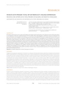
Fig. 1. — Standing anteroposterior pelvic radiograph suitable for hip templating. Anatomical landmarks : 1. Femoral shaft ; 2. Greater trochanter ; 3. “Saddle” ; 4. Lesser trochanter ; 5. Acetabular roof ; 6. Teardrop. Landmarks for radiographic quality assessment : I. Foramen obturatum ; II. Symphysis ; III. Sacrum ; IV. Distance between symphysis and sacrococcygeal joint.
EVALUATING THE QUALITY OF THE RADIOGRAPH Well exposed, well oriented, good quality standardised AP pelvic radiographs are mandatory for hip templating (fig 1). Although this sounds trivial, in clinical practice, it appears particularly challenging to routinely obtain such radiographs. Rather than standard pelvic radiographs, which are generally centred on the sacrum, a low AP pelvic radiograph with the x-ray beam centred on the pubis is preferred for hip templating. As such, the whole proximal third of the femur is visible and is located more or less in the same horizontal plane as the xray source, avoiding excessive distortion. To evaluate functional leg-length discrepancies and pelvic tilt in the frontal and sagittal plane, AP pelvic radiographs should be taken in standing position with both iliac spines at the same distance from the film. Acta Orthopædica Belgica, Vol. 76 - 4 - 2010
As such, the symphysis pubis should project on a line through the middle of the sacrum. The natural pelvic tilt in the sagittal plane can be estimated by the distance between the projection of the sacrococcygeal joint and the upper border of the symphysis (fig 1 : IV). When the pelvis is in neutral inclination the distance between the sacrococcygeal joint and the symphysis is 32 mm (range : 8-50 mm) in women and 47 mm (range : 15-72 mm) in men. The distance increases when the pelvis is tilted forward and decreases when the pelvis is tilted backwards (20). To estimate the length of the femoral neck, both femora should be positioned in 15 to 20° of internal rotation, corresponding to the natural femoral anteversion (1). As such, the femoral neck is parallel to the film and projects in its full length. Radiographs taken with the femur in more or less internal rotation will underestimate the femoral neck length and the femoral offset (fig 2).
PRIMARY HIP ARTHROPLASTY TEMPLATING ON STANDARD RADIOGRAPHS
A
B
435
C
Fig. 2. — Influence of the femoral rotation on the neck length as measured on a radiograph. A. Femur positioned in 15° of internal rotation corresponding to the femoral neck anteversion. The femoral neck is parallel to the film and a correct estimation of the femoral offset can be made. The projection of the lesser trochanter is 2.3 ± 3.1 mm (12). B. Femur positioned in neutral position. The femoral offset is underestimated and the projection of the lesser trochanter is broadened. C. Femur positioned in excessive internal rotation. The femoral offset is underestimated and the projection of the lesser trochanter is narrowed.
Hananouchi et al (12) showed that the femoral rotation can be judged by measuring the projection of the lesser trochanter. When the femoral neck is parallel to the film, the lesser trochanter is on average 2.3 ± 3.1 mm broad (fig 2) and in most cases less than 5 mm of lesser trochanter should be visible medially from the proximal femur. Hip templating can only be accurate if the radiographic magnification factor is controlled and taken into account. Radiographic magnification is caused by the divergence of the x-ray beam as it travels from the source to the object and the film. To control the magnification factor, the relation between the x-ray source, the object (hip of the patient) and the film must be fixed. Increasing the distance between the source and the object or decreasing the distance between the object and the film will decrease the magnification factor. Controlling the
source-film distance is easy but, because patients have different morphologies, it is not always simple to position the hips exactly at the same level between the source and the film. To be less dependent on an accurate radiographic set-up, calibration objects can be used. Ideally these objects (generally metal spheres of known dimensions) should be positioned at the level of the hip joint in the anteroposterior plane, in order to achieve the same magnification. The only instance where this is possible is when a hip prosthesis with known dimensions has been implanted on the contralateral side. The best alternative is to position the calibration object close to the pubis between the patient’s legs and in the plane of the greater trochanter (25). However, that location might not be well perceived by patients and radiology technicians, who prefer to position the marker at the level of the greater trochanter. This Acta Orthopædica Belgica, Vol. 76 - 4 - 2010
436
T. SCHEERLINCK
Fig. 3. — Mechanical landmarks : 1. Hip rotation centre ; 2. Longitudinal axis of the proximal femur ; 3. Femoral offset ; 4. Acetabular offset ; 5. Hip length. 6. The “leg length discrepancy” is calculated as the difference between the distances 6L and 6R.
position induces more projection errors and may lead to significant magnification errors in clinical practice (21). DEFINING MECHANICAL REFERENCES Hip, femoral and acetabular rotation centre The hip rotation centre can be defined as the point around which all hip movements occur. If the acetabulum and the femoral head are preserved, the acetabulum and the femoral head are concentric and both, the acetabular and the femoral rotation centre project on the hip rotation centre. As such, the hip rotation centre can easily be found as the centre of a circle fitted to the projection of the femoral head or the acetabular roof and medial wall (fig 3). On the other hand, if pathology has deformed the acetabulum and/or the femoral head, the hip rotation centre may be difficult to find and its position Acta Orthopædica Belgica, Vol. 76 - 4 - 2010
may vary during hip movements. For this reason, it is easier and more useful to define the “original” femoral and the “original” acetabular rotation centres, i.e. the rotation centre of the femoral head and acetabulum before deformation occurred. These original rotation centres can be found as the centre of a circle fitted on the preserved part of the femoral head (generally the inferior 1/3) and the preserved part of the acetabulum (generally the teardrop and the medial wall). Fitting both rotation centres on each other, generally gives a good idea of how the hip joint must have looked like before deformation. Femoral, acetabular and combined offset The femoral offset is defined as the shortest distance between the femoral rotation centre and the longitudinal axis of the proximal femur (4,16). The longitudinal axis can be found by drawing a line between the middle of the projected femoral canal,
PRIMARY HIP ARTHROPLASTY TEMPLATING ON STANDARD RADIOGRAPHS
measured at two different levels in a part of the proximal femur that appears to be symmetrical (fig 3). If pathology has deformed the femoral head, the original femoral offset can be estimated as the distance between the original femoral rotation centre and the longitudinal axis of the proximal femur. As the radiographic image is a 2D projection of a 3D structure, the femoral offset, as measured on the film, depends on femoral rotation. Lack of parallelism between the plane of the femoral neck and the film will inevitably underestimate the femoral offset. The femoral offset is important because it controls the tension and moment arm of the abductor muscles (16), the tension of the soft tissues (4), the wear of the acetabular component (15) and the load imposed on both, the acetabular and femoral implants (4). Failure to restore the femoral offset may lead to excessive wear (19), limping and/or hip instability (11). On the other hand, excessive femoral offset has the potential to overload the femoral implant (6), to generate micromotion at the implant-bone interface (18) and to cause pain in the abductor muscles and the region of the greater trochanter (1). The acetabular offset can be defined as the shortest distance between the acetabular rotation centre and a perpendicular to the interteardrop line, drawn along the projection of the most distal part of the teardrop (fig 3). If pathology has deformed the acetabulum, the original acetabular offset can be found in the same way, but replacing the hip rotation centre with the original acetabular rotation centre. The acetabular offset is important because it controls the tension of the abductor muscles and the soft tissues as well as the lever arm of the body weight and thus the load transmitted to the acetabulum (4). Decreasing the acetabular offset by excessive medialisation of the acetabular component may lead to limping and/or hip instability. Increasing the acetabular offset may overload the cup (4). The combined offset can be defined as the sum of the femoral and acetabular offset. This parameter is relevant for the tension of the abductor muscles and soft tissues, as it controls the relative position of the greater trochanter and the pelvis. On the other hand, it cannot be used to estimate the abductor muscle
437
and body lever arms or the joint reaction forces, because it does not take into account the exact location of the hip rotation centre. Leg length versus hip length The “leg length” can be defined as the distance between a fixed reference point on the pelvis, e.g. the inferior tip of the teardrop, and the floor, with the distance being measured on a standing AP pelvic radiograph. Because the floor is generally not visible on a pelvic radiograph, left/right “leg length discrepancy” is reported rather than absolute values. This can be calculated as the difference in distance between the inferior tip of the teardrop and a horizontal line parallel to the floor (fig 3). The “hip length” can be defined as the shortest distance between the inferior tip of the teardrop and a horizontal line through a fixed point on the proximal femur, e.g. the upper part of the lesser trochanter (fig 3). As this measurement is influenced by hip abduction/adduction and flexion/ extension, both hips should be in a similar position to make left/right measurements comparable and to calculate “hip length discrepancy”. Because of bony abnormalities outside the hip joint (e.g. osteotomies or malunions of old fractures in the lower limb) or due to functional limitations (e.g. flexion contracture of the knee, flexion or adduction contracture of the hip), leg length discrepancy does not necessarily reflect a lengthening or shortening at the level of the hip joint itself. As such, it can be of interest to compare “leg length” and “hip length” discrepancy. In case of large differences between both measurements, clinical examination and careful history should reveal the source of the difference. If this source is likely to be addressed with the hip replacement, e.g. flexion contracture of the hip joint, it might be advisable to correct hip length discrepancy alone and to neglect the apparent leg length discrepancy, which will correct itself with the restoration of a better hip mobility (fig 4). On the other hand, if the difference between leg length discrepancy and hip length discrepancy is located outside the hip joint, partial or full correction of leg length discrepancy during hip replacement should be considered. Acta Orthopædica Belgica, Vol. 76 - 4 - 2010
438
T. SCHEERLINCK
Fig. 4. — Difference between leg and hip length discrepancy. In this case, the leg length discrepancy is 12 mm (L > R ; black arrow), whereas the hip length discrepancy is 3 mm (46-43 ; L > R ; white arrow). Clinical examination revealed a flexion contracture of the right hip, which is expected to disappear after hip replacement. In this case, correcting the hip length discrepancy (3 mm) is adequate. Correcting the leg length discrepancy would result in over-lengthening the right side by 9 mm.
CHOICE AND POSITIONING OF THE IMPLANTS After marking the anatomical landmarks, evaluating the quality of the radiograph and defining the mechanical references, a fitting implant size is chosen for both the acetabular and the femoral component. In most cases the aim will be to restore the original hip anatomy and biomechanics. However, in some cases this will not be possible or advisable, and compensations for failing to do so will have to be considered. Restoring the original anatomy and hip mechanics If the anatomy of the hip to be replaced is well preserved, templating can easily be performed on the pathological side. However, when the pathological hip is deformed or radiographed in an inappropriate position, it can be easier to template the healthy contralateral hip and to mirror the result to the pathological side. Acta Orthopædica Belgica, Vol. 76 - 4 - 2010
In a first step, the cup is chosen to fit the acetabular cavity and to restore the original acetabular rotation centre. The template of the acetabular component is positioned with an abduction angle of 40° to 45° between the longest axis of the cup and the interteardrop line (8,1,24). However, for hard-onhard bearings, especially metal-on-metal, the abduction angle should be aimed at 40° rather than 45°, in order to reduce the chances of a deleterious steep cup position (14,23). With the acetabular template in place, the insertion depth compared to the medial acetabular wall, the insertion height compared to the inferior border of the teardrop and the cup containment or overhang compared to the lateral border of the acetabular roof are noted (fig 5). These anatomical landmarks are easy to identify during surgery and will help the surgeon to position the cup as planned. In case of protrusio acetabuli, i.e. when the femoral head projects medially from Köhler’s line, lateralising the acetabular component and grafting the medial acetabular wall can allow to restore the original acetabular rotation centre, avoiding impingement and increasing bone stock (1). In dysplastic hips, the goal is to restore the original rotation centre whenever possible. However, as the acetabulum is often shallow with a vertical roof, obtaining sufficient lateral coverage may be difficult. This may require bone grafting of the lateral and superior portion of the acetabulum. In some cases, when cup coverage is insufficient and cannot be solved with bone grafting, a small cup inserted in a medialised position or even a high rotation centre may have to be considered (1). Yet, this choice will have repercussions on the planning of the femoral component (see the section on “Compensating for failure to restore the original hip rotation centre”). Second, a femoral implant is chosen to fit the medullary canal. The longitudinal axis of the implant is positioned parallel to the longitudinal axis of the femur and the approximate insertion depth is chosen in order to correctly restore the leg or hip length. Fine tuning to restore the offset and the original femoral rotation centre, can be done in three different ways : (i) medialising or lateralising the femur by using a standard or offset stem, (ii) choosing a stem with a different neck-shaft angle
PRIMARY HIP ARTHROPLASTY TEMPLATING ON STANDARD RADIOGRAPHS
A
B
439
C
Fig. 5. — Hip templating to restoring the original hip rotation centre. A. Due to the important femoral head destruction the original femoral rotation centre (FRC) is more proximal and more lateral than the original acetabular rotation centre (ACR). B. The acetabular component is positioned in 40°-45° of inclination to restore the ACR, the femoral component is positioned along the longitudinal axis of the proximal femur to restore the FRC. The lateral overhang and the position of the inferior border of the cup compared to the teardrop are noted (white arrows) as well as the height and orientation of the femoral neck cut (grey line). These landmarks will help to reproduce the exact implant position during surgery. C. Final result after hip replacement.
and (iii) modifying the length of the femoral neck. Choosing between a standard and an offset stem is the easiest option because it generally does not alter leg/hip length much. A stem with a more horizontal neck-shaft angle increases offset but decreases leg/hip length. Leg shortening should then be compensated for by using a femoral head with a longer neck and/or by positioning the stem more proud. Using a femoral head with a longer neck increases both the offset and the leg/hip length, and requires a more distal stem insertion to avoid lengthening. If the femur has been radiographed in excessive external or internal rotation, i.e. when the projection of the lesser trochanter is inadequate, the radiograph underestimates the femoral offset and this should be taken into account by choosing a femoral implant with more offset. A repeated “trial and error technique” allows selecting the correct stem size and type as well as the right neck-shaft angle and neck length. With the appropriate template in place, the insertion depth and the level and orientation of the femoral neck cut are noted in relation to the greater and lesser trochanter (fig 5). Traditionally, the distance between the lesser trochanter and the medial border
of the femoral neck cut is used as a landmark to evaluate the height of the neck cut and the stem insertion depth. However, when a small incision is used, the lesser trochanter can be difficult to visualise. In that case, the femoral neck cut orientation together with the distance between the proximal end of the neck cut and the saddle (junction piriformis fossa / base of the neck ), can be used as a landmark. Compensating for failure to restore the original hip anatomy When restoring the original hip anatomy is no option, it is important to restore the combined femoro-acetabular offset and the hip length. When acetabular offset is decreased and the hip rotation centre is medialised, femoral offset should be increased (fig 6). On the contrary, a lack of femoral offset can be compensated for by increasing the acetabular offset, i.e. by lateralising the hip rotation centre. The spatial relation between the pelvis and proximal femur is thus maintained, and soft tissues and gluteus muscles balance is preserved. Similarly, a high or a low hip rotation centre should be comActa Orthopædica Belgica, Vol. 76 - 4 - 2010
440
A
T. SCHEERLINCK
B
C
Fig. 6. — When the original hip rotation centre cannot be restored, it is important to respect the anatomic relation between the greater trochanter and the pelvis. This allows a proper tension of the gluteal muscles (thick grey line). A. Hip templating restoring the original hip rotation centre. B. Inserting the cup in a medial position, medialises the implant rotation centre (black dot) and decreases the acetabular offset (full black arrow). This can be compensated for by increasing the femoral offset (full white arrow). The hip length (dotted arrow) remains unchanged. C. Inserting the cup in a high position results in a high rotation centre and a decrease in hip length. This decrease can be compensated for by inserting the stem more proud. The acetabular and femoral offset remain unchanged.
pensated for by inserting the stem more or less proud (fig 6). Soft tissue and muscle balancing is also crucial when the goal is to lengthen or to shorten the leg. During a lengthening procedure it might be advisable to limit the soft tissue tension and to decrease the combined femoro-acetabular offset by medialising the cup and/or using a low-offset stem. On the other hand, shortening the leg should be associated with a proportional increase of the combined offset to avoid dislocations and gluteal muscle weakness. Strategies for extreme varus or valgus hips The biomechanics of extreme varus or valgus hips can be difficult to restore with standard femoral implants. If the femoral offset lies outside
Acta Orthopædica Belgica, Vol. 76 - 4 - 2010
the offset range of the stem, several options are available to optimise hip biomechanics. In a varus hip, the excessive femoral offset can often be restored with a high-offset stem combined with a long-neck head. To avoid limb lengthening a distal neck cut and a low stem insertion position are often required. If this is not enough, a large cup positioned as laterally as possible and/or a cup with a lateralised insert both enlarge the acetabular offset (fig 7A) and the combined femoro-acetabular offset and restore correct soft tissue tension. However, lateralising the acetabular rotation centre should only be considered as a last option, because it also increases acetabular loading (4). In a valgus hip, the lack of combined offset due to a decreased femoral offset should be respected to avoid trochanteric pain by over-tightening the soft
PRIMARY HIP ARTHROPLASTY TEMPLATING ON STANDARD RADIOGRAPHS
441
B
A
Fig. 7. — Restoring hip biomechanics in difficult cases. A. In a severe varus hip, the combined femoral and acetabular offset needs to be maximized without lengthening. A large acetabular component inserted in a lateral position will increase the acetabular offset. A stem with a high offset, combined with a low femoral neck cut (thick grey line) and a head with a long neck, will increase femoral offset. B. In a severe valgus hip, the combined femoral and acetabular offset needs to be minimized without shortening. A small cup positioned against the medial acetabular wall will decrease the acetabular offset. A stem with a low offset, combined with a high neck cut (thick grey line) and a head with a short neck, will decrease the femoral offset. In this example, the radiograph underestimates the femoral offset due to excessive antetorsion of the proximal femur.
tissues. In a first step the combined offset can be reduced by medialising the cup. This is mechanically favourable because it lowers the load on the acetabular component and optimises the abductor lever arm by allowing sufficient femoral offset (4). If femoral offset needs to be reduced further, a lowoffset stem combined with a short-neck head should be considered. However, this will often require a proud stem insertion position to avoid limb shortening (fig 7B). CONCLUSION With the emergence of digital radiographic systems and the increased number of stem options available in many hip replacement systems,
templating is on its come-back. Hip templating allows assessing the reciprocal relation of the different anatomical landmarks, to evaluate hip biomechanics and to anticipate difficulties and pitfalls prior to surgery. In many cases it is found unnecessary by many surgeons. However, unless it is done systematically, it might be difficult, even for the experienced hip surgeon, to detect those hips which will definitely benefit from a proper anatomical and mechanical pre-operative assessment. These cases, unless properly templated, are at risk to suffer inadequate biomechanics and higher complication rates (limping, dislocation, trochanteric pain). Nowadays, as wear and implant fixation problems are getting solved and as patient’s expectations after hip replacement are increasing, it is mandatory to Acta Orthopædica Belgica, Vol. 76 - 4 - 2010
442
T. SCHEERLINCK
focus on restoring hip biomechanics. A systematic approach to hip templating is a first step in the right direction. Reproducing the templated situation combined with a proper surgical implantation technique and respect for the soft tissues should result in better long-term outcome and patient satisfaction. REFERENCES 1. Blackley HR, Howell GE, Rorabeck CH. Planning and management of the difficult primary hip replacement : preoperative planning and technical considerations. Instr Course Lect 2000 ; 49 : 3-11. 2. Bowerman JW, Sena JM, Chang R. The teardrop shadow of the pelvis ; anatomy and clinical significance. Radiol 1982 ; 143 : 659-662. 3. Capello WN. Preoperative planning of total hip arthroplasty. Instr Course Lect 1986 ; 35 : 249-257. 4. Charles MN, Bourne RB, Davey JR et al. Soft-tissue balancing of the hip. The role of femoral offset restoration. J Bone Joint Surg 2004 ; 86-A : 1078-1088. 5. Conn KS, Clarke MT, Hallett JP. A simple guide to determine the magnification of radiographs and to improve the accuracy of preoperative templating. J Bone Joint Surg 2002 ; 84-B : 269-272. 6. Davey J, O’Connor D, Burke DW. Femoral component offset : its effect on micromotion strain in the cement, bone, and prosthesis. Orthop Trans 1989 ; 13 : 566. 7. Della Valle AG, Comba F, Taveras N, Salvati EA. The utility and precision of analogue and digital preoperative planning for total hip arthroplasty. Int Orthop 2008 ; 32 : 289-294. 8. Dore DD, Rubash HE. Primary total hip arthroplasty in the older patient : optimizing the results. Instr Course Lect 1994 ; 43 : 347-357. 9. Eckrich SG, Noble PC, Tullos HS. Effect of rotation on the radiographic appearance of the femoral canal. J Arthroplasty 1994 ; 9 : 419-426. 10. Eggli S, Pisan M, Muller ME. The value of preoperative planning for total hip arthroplasty. J Bone Joint Surg 1998 ; 80-B : 382-390. 11. Fackler CD, Poss R. Dislocation in total hip arthroplasties. Clin Orthop Relat Res 1980 ; 151 : 169-178. 12. Hananouchi T, Sugano N, Nakamura N et al. Preoperative templating of femoral components on plain X-rays. Arch Orthop Trauma Surg 2007 ; 127 : 381-385.
Acta Orthopædica Belgica, Vol. 76 - 4 - 2010
13. Knight JL, Atwater RD. Preoperative planning for total hip arthroplasty. Quantitating its utility and precision. J Arthroplasty 1992 ; 7 : 403-409. 14. Langton DJ, Jameson SS, Joyce TJ, Webb J, Nargol AVF. The effect of component size and orientation on the concentrations of metal ions after resurfacing arthroplasty of the hip. J Bone Joint Surg 2008 ; 90-B : 1143-1151. 15. Little N, Busch C, Gallagher J, Rorabeck C, Bourne R. Acetabular polyethylene wear and acetabular inclination and femoral offset. Clin Orthop Relat Res 2009 ; 467 : 2895-2900. 16. McGrory BJ, Morrey BF, Cahalan TD, An KN, Cabanela ME. Effect of femoral offset on the range of motion and abductor muscle strength after total hip arthroplasty. J Bone Joint Surg 1995 ; 77-B : 865-869. 17. Müller ME. Lessons of 30 years of total hip arthroplasty. Clin Orthop Relat Res 1992 ; 274 : 12-21. 18. O’Connor DO, Davey J, Zalenski E, Burke DW, Harris WH. Femoral component offset : its effect on micromotion in stance and stairclimbing loading. Orthop Trans 1989 ; 13 : 394-395. 19. Sakalkale DP, Sharkey PF, Eng K, Hozack WJ, Rothman RH. Effect of femoral component offset on polyethylene wear in total hip arthroplasty. Clin Orthop Relat Res 2001 ; 388 : 125-134. 20. Siebenrock KA, Kalbermatten DF, Ganz R. Effect of pelvic tilt on acetabular retroversion : a study of pelves from cadavers. Clin Orthop Relat Res 2003 ; 407 : 241248. 21. The B, Diercks RL, Stewart RE, van Ooijen PM, Van Horn JR. Digital correction of magnification in pelvic x rays for preoperative planning of hip joint replacements : theoretical development and clinical results of a new protocol. Med Phys 2005 ; 32 : 2580-2589. 22. The B, Diercks RL, van Ooijen PM, Van Horn JR. Comparison of analog and digital preoperative planning in total hip and knee arthroplasties. A prospective study of 173 hips and 65 total knees. Acta Orthop 2005 ; 76 : 78-84. 23. Walter WL, Insley GM, Walter WK, Tuke MA. Edge loading in third generation alumina ceramic-on-ceramic bearings : stripe wear. J Arthroplasty 2004 ; 19 : 402-413. 24. Wan Z, Boutary M, Dorr LD. The influence of acetabular component position on wear in total hip arthroplasty. J Arthroplasty 2008 ; 23 : 51-56. 25. Wimsey S, Pickard R, Shaw G. Accurate scaling of digital radiographs of the pelvis. A prospective trial of two methods. J Bone Joint Surg 2006 ; 88 : 1508-1512.