ISSN: 2350-0328 International Journal of Advanced Research in Science, Engineering and Technology Vol. 2, Issue 5 , May 2015
Performance Analysis of IC Engine Based on Swirl Induction by Using CFD Bandi.Ramanjulu, Adissu Fulli, D.Jegan Raj, Abera Endesha Bekele Lecturer, Department of Mechanical engineering, Wolkite University, Ethiopia. East Africa. Dean, College of Engineering and Technology Wolkite University, Ethiopia. East Africa. Lecturer, Department of Mechanical engineering, Wolkite University, Ethiopia. East Africa. Head, Department of Mechanical engineering, Wolkite University, Ethiopia. East Africa
ABSTRACT: A good swirl promotes the fast combustion and improves the efficiency. The engine should run at low speeds [1], in order to have low mechanical losses and fast combustion, enabling good combustion efficiency. Therefore to produce high turbulence prior to combustion within the cylinder, swirl induced by the inlet channel within the cylinder head will be helpful. The need of automobile vehicles, still satisfying demands for high performance, necessitates immense efforts to develop innovative engine concepts and produce less emission. In the evaluation of Internal Combustion Engine the performance, efficiency and emission formation depends on the formation of air-fuel mixture inside the engine cylinder. The fluid flow analysis plays an important role for air-fuel mixture preparation to obtain the better engine combustion, performance and efficiency1.Due to the extreme conditions inside a typical ICengine (high combustion temperatures and pressures, precipitation of soot and other combustion products, etc.) experimental techniques are sometimes limited in approaching the above mentioned problem. Alternatively, numerical Techniques (Computational Fluid Dynamics, CFD) offer the opportunity to carry out repetitive parameter studies with clearly defined boundary Conditions in order to investigate various configurations. After of clean observation of all the Research in swirl motion plays an import role to increases in engine performance as well as decrease the emissions KEY WORDS: CFD simulation, Swirl induction, Air-fuel Mixture Tumble motion, Swirl Techniques I. INTRODUCTION Swirl is one of the principal means to ensure rapid mixing between fuel and air in DI diesel engine, and is used in gasoline engines to promote rapid combustion. The swirl level at the end of the compression process dependent upon the swirl generated during intake process and how much it is amplified during the compression process [8]. In DI diesel engine, as fuel is injected, the swirl converts it away from the fuel injector making fresh air available for the fuel about to be injected. Swirl is defined as the large scale vortex in the in-cylinder fluid with the axis of rotation parallel to the piston axis. Swirl, considered as a two-dimensional solid body rotation, persists through the compression and combustion processes [5]. The decay of swirl in an engine cylinder during the compression process is relatively small so that the Overall angular momentum of the swirl vortex is almost conserved [3]. For example, Liou and Sopian (2008) found that turbulence was nearly homogeneous and isotropic near TDC in their engine experiments. They also showed that turbulence intensity near TDC at a given speed was 25-50% greater with swirl than without and then declined continuously with crank angle The induction swirl is generated either by tangentially directing the flow into the cylinder using directed ports or by pre swirling the incoming flow by use of a helical or spiral or helical-spiral ports. Helical ports are more compacted than normal manifold. They are capable of producing more swirl than directed ports at low lifts, but are inferior at higher lifts. Either design creates swirl at the expense of volumetric efficiency. In trying to optimize the port design for both good swirl and volumetric efficiency, current high swirl ports are in part of both directed and different technique inlet manifolds. A numerical grid of a cylinder with helical intake ports as shown in Fig 1.1
Copyright to IJARSET
www.ijarset.com
622
ISSN: 2350-0328 International Journal of Advanced Research in Science, Engineering and Technology Vol. 2, Issue 5 , May 2015
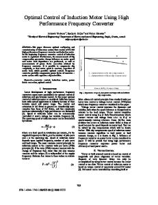
Fig.1.1 computational model of helical inlet port Some parameters to consider in the design of a Ports for swirl are in fig 1.2 these are the radius of the\valve offset Rv and orientation angle α Development work, like that for maximizing the Discharge coefficient, is typically done on steady-flow bench.
Fig 1 .2.intake port showing the definition of the swirl parameters II. LITERATURE SURVEY Flow of air through the manifold and mixing of the fuel with air inside the cylinder is more important in the case of diesel engine because these factors, directly affect the volumetric efficiency, combustion performance, output and emission levels of the engine. Control of flow through the manifold is critical for meeting the emission regulations and fuel economy requirements. Parameters like engine speed, manifold and combustion chamber configuration [6] directly influence the swirl in DI diesel engines and subsequently it plays a vital role in mixing air and fuel inside the cylinder. Optimization of swirl becomes an important aspect in the design of intake systems of diesel engines Nowadays, with the availability of powerful Computers, the CFD prediction methods for in-cylinder flow of IC engines have become popular. They can give very useful information regarding the flow pattern and has the potential to reduce the total development time of the intake system of an IC engine. Engine manufactures require precise engine design to bring the end product to the market in a short time period and hence CFD codes play an important role in IC engine design.Barbouchi [8] presented a flow model to predict the swirl vortices and turbulence in an open chamber cup-in-piston engine. The work was compared with experimental data over a range of engine intake manifold and combustion chamber configurations. Lot of work has been done on engine flow and on the parameters that affect the turbulence, performance and emissions in a DI diesel engine. Arcoumanis C (1994) carried out the Modeling of flow distribution in exhaust manifold. Modifications were made on the inlet and exhaust manifolds based on the results obtained. They also conducted experiments and validated the performance and emissions of the engine. Celik I (2001) presented an experimental analysis for turbulence inside the Copyright to IJARSET
www.ijarset.com
623
ISSN: 2350-0328 International Journal of Advanced Research in Science, Engineering and Technology Vol. 2, Issue 5 , May 2015
combustion chamber of direct injection diesel engine. From This study I understand the effects of piston bowl shape, engine speed, manifold shape and compression ratio on the flow fields in a DI diesel engine. Chiavola et al. (2001) conducted a study on the flow behavior in intake and exhaust system of an internal combustion engine and observed that the flow phenomenon in ducts closely affects the volumetric efficiency of the engine. Many researchers (Brands tatter, 1985; Belardini P, Bertoli C 2008) had conducted experimental / simulation work on flow modeling to study the effect of engine configurations, piston bowl, valve profile, manifold configurations, inlet manifold duct length, pent roof piston etc. Binachi et al. And V.Ganesan&Benny had discussed a study related to the effect of operating parameters in the turbulence and swirl level in DI diesel engine. Flow parameter measurements technique including\ practical and simulation methods are explained in many research papers, viz, [5].From the review of literature, I can analyze the design of inlet manifold configuration is very important in an IC engine. Hence, this information looks up on the effect of helical, spiral, and helical-spiral combined configuration on the induced mean swirl velocity in the piston bowl at TDC, swirl ratio during suction and compression stroke, turbulent kinetic energy variation and volumetric efficiency at engine speed 3000 rpm. III. OBJECTIVE OF THE STUDY • Modeling the engine with inlet valve, exhaust valve and manifold • Effect of inlet manifold configurations on the in cylinder flow • Turbulence in a diesel engine under non-firing Conditions • Effect of different (helical, spiral, helical-spiral) inlet manifold configurations on volumetric efficiency, \turbulence, and swirl in the engine IV. RESULTS OF DIFFERENT CONFIGURATION The in-cylinder air motion before fuel injection process is very important to certify a proper air-fuel mixture. This is due to the fact that in-cylinder air motion plays vital role on the complete combustion in the engine cylinder.
Fig.4.1 CFD simulation of air flow in the IC Engine This strong annular jet flows make a clockwise or counter-clockwise swirl on the intake valve. The piston speed is kept constant at 2500 rpm. A clockwise vortex is visible to be formed at the centre of the engine cylinder, under intake valves. This is a due to the jet motion of air which does not strike the cylinder walls but directly flows to the centre of the cylinder. The jet of air which strikes the walls of the cylinder creates an elongated vortex along the wall.
Copyright to IJARSET
www.ijarset.com
624
ISSN: 2350-0328 International Journal of Advanced Research in Science, Engineering and Technology Vol. 2, Issue 5 , May 2015
Fig.4.2 Crank angle vs Swirl Ratio Creating a swirling vortex in the cylinder has been recognized as a way of enhancing turbulence levels during the compression stroke since the early days of IC Engines [7]. Swirl enhances turbulence during the compression stroke through the following methods: Turbulence generated by the shear at the wall is transported throughout the bulk of the flow by diffusion and swirl generated secondary flows or any protruding objects not on the axis of rotation of the swirl vortex will create turbulence through shear and vortex shedding or a swirl vortex in combination with the squish flow will cause an acceleration of the rotational speed of the vortex as the piston.
Fig.4.3 TKE inside the cylinder for helical manifold at the beginning of compression stroke
Fig 4.4 TKE Inside the cylinder for spiral manifold at the beginning of compression stroke
Copyright to IJARSET
www.ijarset.com
625
ISSN: 2350-0328 International Journal of Advanced Research in Science, Engineering and Technology Vol. 2, Issue 5 , May 2015
Fig 4.5 TKE inside the cylinder for helical-spiral manifold at the beginning of compression stroke
Fig.4.6 Volumetric efficiency of different manifold configuration
Fig. 2.7 Velocity vectors at TDC for five combustion chambers.
V. CONCLUSIONS After the analysis of different manifolds in the previous sections, analysis is extended to compare the effect of different manifold Configurations on flow structure. The helical-spiral manifold geometry creates higher velocity component (W/Vp) inside the combustion chamber at the end of compression stroke. Swirl ratio inside the cylinder and turbulent kinetic energy are higher for spiral manifold. Volumetric efficiency for the spiral helical combined manifold is 10% higher than that of spiral manifold. The summary of the comparison is as follows: 1. Helical-spiral combined manifold creates higher swirl inside the cylinder than spiral manifold. Copyright to IJARSET
www.ijarset.com
626
ISSN: 2350-0328 International Journal of Advanced Research in Science, Engineering and Technology Vol. 2, Issue 5 , May 2015
2. Helical manifold provides higher volumetric Efficiency. 3. Helical-spiral combined manifold provides higher mean swirl velocity at TDC of compression.. 4. In-cylinder calculations of the intake and compression strokes of a DI Diesel engine equipped with two intake valves were carried out. The resulting flow field was analyzed for different combustion chamber shapes and compared with a limited number of measurement REFERENCES [1] C. Garth, R. S. Laramee, X. Tricoche, J. Schneider, and H. Hagen. Extraction and visualization of swirl and tumble motion from engine Simulation data- available at [2] Large Eddy Simulation of the Flow and Mixing Field in an Internal Combustion Engine, Dmitry Goryntsev, Darmstadt, October 2007 [3] Heywood J.B.: Internal combustion engine fundamental. McGraw- Hill International Editions, New York, 1988. [4] Robert S. Laramee, Daniel Weiskopf, Jurgen Schneider, Helwig Hauser- Investigating Swirl and Tumble Flow with a Comparison of Visualization Techniques [5] Influence of in cylinder air swirl on diesel engine performance and emission- International Journal of Applied Engineering and Technology ISSN: 2277-212X (Online). [6] CFD Investigation of Fluid Flow and Turbulence Field Characteristics in a Four-Stroke Automotive Direct Injection Engine by Wendy Hardyono Kurniawan, Shahrir Abdullah, Kamaruzzaman Sopian, Zulkifli Mohd. Nopiah and Azhari Shamsudeen. Journal – The Institution of Engineers, Malaysia (Vol. 69, No.1, March 2008) [7] Literature Review – Swirl and Tumble Motion. [8] Turbulence study in the internal combustion engine- Z. Barbouchi and J. Bessrour. Journal of Engineering and Technology Research Vol.1 (9), pp. 194-202, December, [9]. V.Ganesan&Benny paul Flow field development in a direct injection diesel engine with different manifolds [10].Arcoumanis C, Whitelaw JH, Hentschel W, Schindler K-P. Flow and combustion in a transparent 1.9 litre direct injection Diesel engine. IMechE D 1994; 208:191–205. [11] Arcoumanis C, Bicen AF, Whitelaw JH. Squish and swirl–squish interaction in motored model engines. J Fluids Eng 1983;105. [12] Arcoumanis C, Whitelaw JH. Fluid mechanics of internal combustion engines. Proc IMechE 1988; 201(C1):57–74. [13] Arcoumanis C, Begleris P, Gosman AD, Whitelaw JH.Measurements and calculations of the flow in a research Diesel engine. SAE 861563, 1986. [14] Belardini P, Bertoli C, Corcione FE, Valentino G. L_impiego integrato dell_anemometria e della modellistica multi dimensional per 1_analisi del comportamento fluidodinamico dei m.c.i. ATA 4-1988, vol. 41, no. 4, 1988. p. 248. [15] Bopp S, Vafidis C, Whitelaw JH. The effect of engine speed on the TDC flow field in a motored reciprocating engine. SAE 860023, 1986. [16] Brandst€atter W, Johns RJR, Wigley G. The effect of inlet port geometry on in-cylinder flow structure. SAE 850499, 1985. [17] Celik I, Yavuz I, Smirnov A. Large eddy simulations of in cylinder turbulence for internal combustion engines: a review. Int J Engine Res 2001;2(2):119–48.
AUTHORS BIOGRAPHY Er .Mr Bandi Ramanjulu working as a Lecturer in the Department of mechanical engineering, Wolkite University, Ethiopia. Completed M.Tech In the field of Internal combustion engines from JNT University Anantapur, Andhra Pradesh in 2011.Have 4 years of teaching and industry services in reputed organizations. Interested in the research field of internal combustion engines, presented papers in national and international conferences.
Copyright to IJARSET
www.ijarset.com
627