Decades of Timber Knowledge Rolled into Steel
July 2009
heet
ew, Climaseal, #3 Philips Head drive Material Carbon Steel
performance in steel house frames and Benefits Higher resistance to loosening & reduced strip torque Ensures maximum pullout and strip torque Easy to start & align
nd make sure they are within tolerance for
volt or higher impact screw driver impact tool. ntil seated material is clamped.
ad. Appropriate safety factors are recommended
WALL FRAME
Installation Guide Revision 1.4
Copyright Notice Copyright © 2015 AusSteel Global Corporation Pty Ltd. This installation guide is subject of copyright protection and related rights. All rights are reserved. This document may not, in whole or part, be copied, photocopied, reproduced, translated or redacted to any electronic medium or machine-readable form without prior consent, in writing, from AusSteel Global Corporation Pty Ltd. Trade marks
The words AUSSTEEL and THE ULTIMATE STEEL BUILDING SYSTEM and AS and AusSteel Logos are trade marks and intellectual property of AusSteel Global Corporation Pty Ltd. Other company, brand or product names are for identification purposes only and may be trade marks or registered trade marks of their respective holders.
TABLE OF CONTENTS SECTION A: GENERAL SCOPE A-1 A-2 A-3 A-4 A-5
CRITERIA APPLICATION DOCUMENTATION TRANSPORTATION, ON-SITE HANDLING & STORAGE SAFETY & CONSTRUCTION EQUIPMENT
SECTION B: INSTALLATION OF WALL FRAMES B-1 B-2 B-3 B-4 B-5 B-6 B-7
PRIOR TO CONSTRUCTION & IDENTIFICATION ERECTION OF WALL FRAMES TIE-DOWN REQUIREMENTS STRAP BRACING & SHEET BRACING BULKHEAD BEAM INSTALLATION GARAGE, PORCH & VERANDAH BEAM INSTALLATION SHOWER CUT-OUTS & BATH INSET CHANNEL
SECTION C: FIT-OUT & FOLLOWING TRADES C-1 C-2 C-3 C-4 C-5 C-6
INSTALLATION OF SERVICES EXTERNAL DOORS & WINDOWS BRICK TIES & DAMP PROOF COURSE EXTERNAL CLADDINGS PLASTERBOARD WALL & CEILING LININGS INTERNAL DOOR JAMBS, ARCHITRAVES & SKIRTING BOARDS
SECTION D: GENERAL INFORMATION D-1 D-2
Page 3
ON-SITE FRAME MODIFICATIONS FASTENING DESCRIPTIONS
AusSteel Pty Ltd. Wall Frame Installation Guide
© Copyright 2015
SECTION A: GENERAL SCOPE A-1 CRITERIA The Ultimate Steel Building System wall frames and trusses by AusSteel are designed, engineered and manufactured in accordance with Australian Standards. AusSteel takes pride in its dedication to providing a secure, clean and efficient work place for its employees and associates. It is essential that all respective parties involved are familiar with the guidelines and requirements set out in all documents supplied by AusSteel to guarantee that the product’s full potential is achieved. The guidelines in this document are a simple sub-set of the following Australian Standards and BCA requirements; • AS/NZS 4600-2005 • AS 4100-1998 • AS 3623-1993 • AS 3566-1-2002 • AS 4055-2006 • AS/NZS 1170 Part 0, 2002 • AS/NZS 1170 Part 1, 2002 • AS/NZS 1170 Part 2, 2002 • AS/NZS 1170 Part 4, 2007 • NASH Standard Part 1 • NZS 1170 Part 5, 2007
Cold Formed Steel Structures Steel Structures Code Domestic Metal Framing Self Drilling Screws Wind Loads for Housing Structural Design Actions – General Principles Structural Design Actions – Permanent, Imposed and other Actions Structural Design Actions – Wind Actions Structural Design Actions – Earthquake Loads Residential and Low Rise Steel Framing Structural Design Actions – Earthquake Actions New Zealand
It is advised that the Australian Standards should be read in conjunction with all documents supplied by AusSteel. AusSteel acknowledges Bluescope Steel and the National Association of Steel Framed Housing (NASH) for permission to reference some of the technical information from within their specific guidelines. AusSteel also acknowledges Summermore Structural Engineers for technical support.
A-2 APPLICATION The assembly and construction method provided in this guide is to be applied once the concrete slab has been laid and properly cured or a floor frame or platform has been erected. This procedure explains the installation, spacing and fastening methods required to assemble an AusSteel steel frame. This document aims to apply to AusSteel steel wall frames and trusses within the subsequent general limitations; a) Residential structures and light commercial structures, b) Maximum wind rating of N2 – C4, c) Maximum truss spacing of 1800mm, d) Tile and sheet roof construction, e) Standard stud spacings of 450mm to 600mm centres, f) Standard wall heights up to 6000mm, g) 70-90mm standard stud widths, h) Single and double storey construction. For use above the listed limitations, AusSteel will provide design documentation and engineering to substantiate the required stipulations.
A-3 DOCUMENTATION
Responsibility to provide all relevant information concerning construction and specifications rests on the builder prior to fabrication. Failure to provide copies of subsequent changes and variations before fabrication will result in extra charges and on-site work at the expense of the builder.
Page 4
AusSteel Pty Ltd. Wall Frame Installation Guide
© Copyright 2015
SECTION A: GENERAL SCOPE AusSteel will provide the following documentation upon delivery of our Ultimate Steel Building System wall frames and trusses; - Yard Sheet (Ancillaries) - Wall Framing Layout - Roof Framing Layout Upon request, AusSteel can also include Wall and Truss Certification in conjunction with Wind Bracing Design to the required authorities. Hard copies can be posted to the address given at the time of ordering.
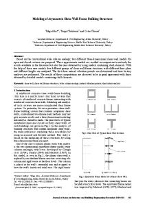
A-4 TRANSPORTATION, ON-SITE HANDLING & STORAGE In most cases, transportation will be organised by AusSteel. However, on the occasion of customer organised transportation, AusSteel is exempt from responsibility for any damages pertained to the load after it has left the premises. AusSteel will take great care to ensure safety and prevent damage to the load in the process of lifting, loading, and transportation of steel frames. When a crane is used to unload, appropriate lifting methods will be enforced to minimise racking loads or local distortion of members. When using a crane, trusses should be slung from the top chord panel points. When slinging wall frames, place the slings at the plate and stud connection point. It is imperative that you do NOT use chains as slings in the process of lifting the frames and trusses, as this can result in damage to the product. Slings must be positioned at equal distances from the truss or wall centreline. The slings should be distanced about one-third to one-half the length apart. The angle between sling legs should not exceed 60 degrees at any time. In the case of a truss with a span greater than 9000mm, a spreader bar or strong back is recommended to avoid warping and damage to the truss. These spreader bars should be attached to web-chord joints. Refer to Drawing No. 001 NOTE: Never lift trusses by the apex joint alone. Placement of walls and trusses may also be aided by pulling the frames and trusses along skids, placed 3000mm apart to avoid sagging between supports. In the case of roof design, there is often multiple truss types, thus each truss type should be separated where possible. Components such as jack rafters and hip rafters should also be isolated. This will reduce double-handling during erection. NOTE: When moving or placing any materials by hand be cautious not to damage the components. Examination of wall frames and trusses should be carried out on arrival to site. It is vital that any damaged parts be reported immediately to guarantee that appropriate repairs are made. Do NOT site repair without prior approval from AusSteel. Doing so may comprimise the structural integrity. AusSteel remains exempt from liability for any site rectification without prior approval. To maintain the integrity of our product, all steel wall frames, trusses and ancillaries must be kept dry and stacked off of the ground to ensure ventilation. It is vital that they are protected from water and condensation being trapped between adjacent surfaces. In the event the bundles or packs become wet, all components should be separated, wiped dry with a clean cloth and placed in a manner that allows for free circulation of air to complete the drying process. ADVICE: Avoid contact with, or exposure to runoff from the following building materials and environmental conditions. These can be detrimental to coated steel products and compromise structural integrity. These include Incompatible metals (e.g. Lead or copper), Building materials subject to cycles or dryness/wetness, or which have excessive moisture content (e.g. improperly seasoned timber), Industrial, agricultural, marine or other aggressive atmospheric conditions, Materials which have been treated with preservatives (e.g. CCA or tanalith-treated timber).
Page 5
AusSteel Pty Ltd. Wall Frame Installation Guide
© Copyright 2015
SECTION 1 SCOPE & GENERAL SECTION 1 SCOPE & GENERAL Drawing No. 001 Drawing No. 001 SECTION A: GENERAL SCOPE
Drawing No. 001
Crane Crane
Brace for Lateral Movement of Truss
60o or Less
Brace for Lateral Movement of Truss Spreader Bar
Crane 60o or Less 1/3 to 1/2 span
Vertical Sling
SLING TRUSS
1/3 to 1/2 span
Brace for Lateral Movement of Wall Spreader Bar
AL
Crane 60o or Less
Vertical Sling
Crane Brace for Lateral Movement of Wall
5
60o or Less
SLING WALL
5
Page 6
AusSteel Pty Ltd. Wall Frame Installation Guide
© Copyright 2015
SECTION A: GENERAL SCOPE A-5 SAFETY & CONSTRUCTION EQUIPMENT The following equipment is recommended for use when erecting an AusSteel steel frame. a) Personal Protective Equipment - Hearing protection (when using power tools) - Safety glasses or eye protection - Protective gloves - Power lead stands or insulated hooks - Earth leakage circuit breaker for power tools b) Power Tools - Electric or Battery screw gun (Impact Driver) - Electric drill/Hammer drill - (4-9”) Angle grinder c) Power Tool Accessories - Suitable metal cutting discs - Socket/Ratchet bar up to 150mm long - 8mm (5/16”) hexagonal socket - No 2 Phillips head bits - No 3 Phillips head bits - Masonry anchor ties (e.g. anchor screws or dynabolts) - Metal/Masonry drill bits - Heavy duty power leads d) Hand Tools - Chalk line - Left and Right handed tin snips - Spirit level - Vice grips - Step ladder NOTE: The construction and erection of wall frames and trusses must comply with relevant safe work practices for general assembly and construction. Safety systems must not alter the wall frames and trusses or place or put loads onto wall frames and trusses unless designed for that purpose. NOTE: Earth leakage breakers are mandatory on building sites. To prevent the risk of electric shock they should be installed between the power supply and electrical tools. It is essential that the finished steel frames are permanently earthed. This must be achieved in accordance with the conventions of the local electrical authority as soon as possible, once the frame is anchored.
Page 7
AusSteel Pty Ltd. Wall Frame Installation Guide
© Copyright 2015
SECTION B: INSTALLATION OF WALL FRAMES B-1 PRIOR TO CONSTRUCTION & IDENTIFICATION Please be aware of the following guidelines before constructing AusSteel steel wall frames. NOTE: All wall frames and trusses should be examined upon arrival to site. Any damaged parts must be reported immediately to ensure appropriate adjustments and repairs are made. Do NOT site repair without approval from AusSteel. AusSteel remains exempt from any liabilities for any site rectification without prior approval. a) Frame and Slab/Sub-Floor Dimensions MUST be compatible Before construction and component identification measure your slab or floor to guarantee that the frame will rest comfortably within its dimensions. This will reveal any differences or variations between the two that must be allowed for during set-out. b) Frame Set-out MUST follow architectural plans To guarantee that all relevant dimensions are transferred to the slab/sub-floor the set-out must be made using the Architectural plans. c) Frames MUST be Installed Right Way Up & Right Way Around To make sure every wall frame is set up correctly, use the AusSteel Wall Frame Numbering System and Wall Framing Layout. Note: Be sure that the open face of the noggin is directed towards the bottom to ensure the frames are the correct way up. WALL FRAME NUMBERING SYSTEM: Wall frames are numbered during the detailing and fabrication process to accurately identify them. Junction numbers are also incorporated into this process which refer back to the Wall Framing Layout. Drawing No. 002 illustrates the AusSteel numbering system. d) Site Modifications MUST be Checked by AusSteel If required by the client, minor modifications to wall frames can be made easily on-site. To cover any structural implications ALWAYS check with AusSteel before carrying out any modifications. Refer to Section D-1: On-Site Frame Modifications e) Statutory Regulations MUST be adhered to During the construction process all statutory regulations must be complied with by following trades. IMPORTANT NOTE: Refer to the Wall Framing Layout while matching the junction numbers to be sure that a wall frame is not installed upside down or the wrong way around. Numbers should also be maintained the right way up. Before fixing down wall frames ALWAYS refer back to the Architectural Plans to be sure construction and set out is correct. All construction work completed on site, following the erection of the wall frames, must comply with statutory regulations.
Page 8
AusSteel Pty Ltd. Wall Frame Installation Guide
© Copyright 2015
SECTION B: INSTALLATION OF WALL FRAMES Drawing No. 002
Wall Panel Numbering System
Note: In assembly, bottom and top plates are marked with panel numbers and end studs are marked with junction numbers as per the layout. The diagram to the right shows the standard numbering system
Sample Section of Wall Frame Layout Page 9
AusSteel Pty Ltd. Wall Frame Installation Guide
© Copyright 2015
SECTION B: INSTALLATION OF WALL FRAMES B-2 ERECTION OF WALL FRAMES The construction and erection sequence for a steel framed building is generally the same as that for timber framing. The advantage of the AusSteel Ultimate Steel Building System is its light weight and rigidity allowing for ease of manoeuvrability and construction without compromising strength. Below is a suggested constructed sequence: STEP 1: Read the entire set of Architectural and fabrication plans. STEP 2: Using a chalk line, mark out wall frame positions on the floor in accordance with your AusSteel frame layout. Compare diagonals to ensure that that the building perimeter and individual rooms are square. AusSteel recommends you mark the wall frame numbers on the slab at their respective locations to make construction easier and prevent mistakes. Take note of the external corner of the smallest room, as this will be the most convenient place to start erection. STEP 3: Open the appropriate packs and indentify each frame using the wall frame numbering system and the Wall Framing Layout. Lay the external frames around the site, near their respective allocated positions on the Wall Framing Layout in such a way that allows for the frames to be lifted into position when necessary. Stack the internal walls inside the slab boundary at the corner diagonally opposite the one in which construction will begin. Stack the frames according to which one you will use first (at top of stack) down to the one you will use last (at bottom of stack).
IMPORTANT NOTE: Under all external wall frames fastened to ground concrete slabs, an impermeable membrane should be laid. The membrane should extend up the weather side lip of the bottom plate. This is in accordance with good building practices and is a condition of Bluescope Steel’s warranty on house framing made from TrueCore steel. An impermeable membrane is not required if sufficient ventilation is supplied to a frame fixed to a suspended floor and a minimum gap of 400mm is allowed between the underside of the floor framing and current existing ground level. Suitable impervious membranes include Polyethylene and other products specified in BCA Volume 2, Section 3.3.4.4.
Page 10
AusSteel Pty Ltd. Wall Frame Installation Guide
© Copyright 2015
SECTION B: INSTALLATION OF WALL FRAMES STEP 4: Beginning from the aforementioned corner, stand and fix together the first two selected external wall frames to form a corner aligned with the chalk lines. Make sure to check which frame butts against the other on the Wall Framing Layout. Once checked, square and align the two wall frames and attach with two #10-16x16mm hex head tek screws at each of the following locations: the bottom plates, noggin line and top plates of each frame.
Refer to Drawing No. 003 for common wall junction configurations.
Page 11
AusSteel Pty Ltd. Wall Frame Installation Guide
© Copyright 2015
SECTION B: INSTALLATION OF WALL FRAMES Additional structural support may be required by some wall frame connections to form a rigid joint. This is usually the case when the frame has been subject to on-site rectifications/alterations. Examples of this are: when after frame modification an internal wall does not butt against the appropriate studs; and when the structural base is inadequate for fastening. Refer to the design engineer for ANY structural modifications to the frame. Refer to Section B-1 On-Site Frame Modifications STEP 5: Build the rest of the structure out across the floor starting from the free-standing corner. All internal walls must be inside the slab perimeter before erecting the building perimeter. Do not close off a room until each frame for the subsequent room is in place. Be sure each frame is squared, aligned and temporarily secured before joining the wall frames. Add temporary props or bracing if required to ensure there is always sufficient support for the free-standing structure. This is particularly important on windy days or for long runs of walls. Be sure the structure is aligned and square by referring to the chalk line with the location of each bottom plate during erection.
Page 12
AusSteel Pty Ltd. Wall Frame Installation Guide
© Copyright 2015
SECTION B: INSTALLATION OF WALL FRAMES STEP 6: Repeat STEP 4 erecting adjacent wall frames until the whole frame is upright. The base of the walls should now be aligned with the chalk line. Once this is completed, make sure that all rooms are square by measuring the diagonals again. Using a stringline, check the straightness of the bottom plate for walls greater than 2.4m in length.
Drawing No. 003
45 Junction
(Shown with 135 Mitre Plate)
Three Way Junction
Butt Junction
Corner Junction
Recessed Junction Load Bearing Wall to Non Load Bearing Wall
Non Load Bearing Wall
Page 13
AusSteel Pty Ltd. Wall Frame Installation Guide
© Copyright 2015
SECTION B: INSTALLATION OF WALL FRAMES STEP 7: Fix walls to the floor through the bottom plates with the appropriate fasteners once all walls are aligned with the chalk lines. Refer to fix down sheet supplied with frames. Refer to Section B-3: Tie-Down Requirements STEP 8: If a bulkhead beam or bulkhead frame is required in a wall frame, fit it now as per Section 2.5 Bulkhead Beam Installation NOTE: Unlike verandah and garage beams, bulkhead beams must be set up prior to the frame being plumbed and braced. STEP 9: Tension the strap bracing to rack the walls square and plumb and adjust the alignment and vertical position of the walls. Perform this by placing a straight edge with a spirit level between the top and bottom plate, then tensioning the bracing on the wall to plumb. Gently tightening or loosening each tensioner will provide a means to make fine adjustments. For load bearing walls greater than 2.4m, a string line should be used to straighten the top plate. Refer to Section B-4 Strap Bracing & Sheet Bracing STEP 10: Using an angle grinder or tin snips, cut out bottom plates at all door openings. The cut outs may be used again elsewhere if needed for trimmers or noggins. Spray all grinded cuts with cold gal spray. STEP 11: The frame must be earthed in compliance with local requirements.
B-3 TIE-DOWN REQUIREMENTS
Refer to the Wall Framing Layout for the wind-speed for each job. It is also provided by the customer before detailing. The wind-speed classification and specific job data determine the design of the tie-down requirements by AusSteel. It is imperative that the frame is tied-down as stated on the Construction Information sheet supplied with your site documentation.
AS08060H Ankascrew with SBS-51 Washer Plate
Splitz Anchor with Mudguard Washer
Drive Pin with Integrated Washer
AS08060H Ankascrew with UC70 Cyclone Bracket* (Required on openings over 1200mm)
* Where possible, UC70 brackets will be pre-installed in the wall frame.
Page 14
AusSteel Pty Ltd. Wall Frame Installation Guide
© Copyright 2015
SECTION B: INSTALLATION OF WALL FRAMES B-4 STRAP BRACING & SHEET BRACING
On some occasions, additional on-site bracing is necessary (generally most steel strap bracing is fitted in the factory). If this is the case the additional bracing is required in the form of strap or sheet bracing. Refer to the Wall Framing Layout to view where the additional bracing is needed. a) Factory Fitted Strap Bracing Tension the strap bracing to rack the walls square and plumb and adjust the alignment and vertical position of the walls. Perform this by placing a straight edge with a spirit level between the top and bottom plate, then tensioning the bracing on the wall to perpendicular. Gently tightening or loosening each tensioner will provide a means to make fine adjustments. All strap and stud intersections must be fixed by one #10-16x16mm tek screw. Use wafer head tek screws where walls are lined or clad. In the case of external walls, use hex head tek screws on brick veneer construction, on the cavity side of the frame. b) On-Site Fixing of Additional Strap Bracing Where the studs meet the plates, it is imperative that any additional steel strap bracing must have THREE #10-16x16mm wafer tek screws to each end of the strap bracing. Tension the strap bracing to rack the walls square and plumb and adjust the alignment and vertical position of the walls. Perform this by placing a straight edge with a spirit level between the top and bottom plate, then tensioning the bracing on the wall to perpendicular. Gently tightening or loosening each tensioner will provide a means to make fine adjustments. All strap and stud intersections must be fixed by one #10-16x16mm tek screw. Use wafer head tek screws where walls are lined or clad. In the case of external walls, use hex head tek screws on brick veneer construction, on the cavity side of the frame. c) On-Site Fixing of Sheet Bracing #12-14x20mm hex head screws are to be used to fix any extra sheet bracing in accordance with Drawing No. 004.
Drawing No. 004
Page 15
AusSteel Pty Ltd. Wall Frame Installation Guide
© Copyright 2015
SECTION B: INSTALLATION WALL FRAMES d) Two Storey – Upper to Lower Connection Blocking must be used for adequate tie-down capacity where the ends of strap or sheet bracing land between joists. Fix the upper floor panels down at each end of the bracing panel by using an additional four #12-14x45mm hex head tek screws. AusSteel suppiles the temporary bracing which must be used to align and plumb long walls. The temporary bracing should only be removed after the completion of the roof frame. Responsibility rests with the builder to make sure the structure and all of its components are sufficiently braced, fully tensioned and maintained in a safe and stable condition during the construction phase. No part of the structure shall be allowed to be overstressed or over loaded during the construction phase. B-5 BULKHEAD BEAM INSTALLATION In order to maintain a continuous pitching perimeter for the roof structure bulkhead assembly will occasionally require the use of a beam. STEP 1: Thoroughly examine the entire set of Architectural and Fabrication Plans. STEP 2: Using the Wall Framing Layout and beam numbering system locate the appropriate beams then place the beams around the site near their relevant positions. NOTE: Unless noted on the drawings, beams will be the correct length and will not require cutting. STEP 3: Raise the beam into position and align with walls. Depending on the designated loads, beams will either sit in allocated ‘check-outs’ in studs or on structural posts. Make sure the beam is facing the appropriate way as detailed on the individual wall frame sheet. STEP 4: Using the Wall Framing Layout, establish the bulkhead beam configuration. STEP 5: For beams up to and including C-150’s, screw fix beam using a minimum of FOUR #1214x20mm hex head tek screws at each connection, or as specified. For beams ranging from 200300mm Webbed Beams, screw fix beam using a minimum of SIX #12-14x20mm hex head tek screws at each connection, or as specified. Refer to Drawing No. 005 for typical bulkhead beam connections. Drawing No. 005
For Webbed Beams, fix with a minimum of 6x 12-14x20mm Teks in shear, or as specified. Frames will be pre-notched to accomodate beams. Fix beams with a minimum of 4x 1214x20mm Teks in shear, or as specified.
Page 16
AusSteel Pty Ltd. Wall Frame Installation Guide
© Copyright 2015
SECTION B: INSTALLATION WALL FRAMES B-6 GARAGE, PORCH & VERANDAH BEAM INSTALLATION Garage, porch and verandah beam installation requires similar processes to those explained in section B-5. Regardless of beam usage, beam to beam connections and beam to frame, or post connections will be the same. STEP 1: Thoroughly examine the entire set of Architectural and Fabrication plans. STEP 2: Using the Wall Framing Layout and beam numbering system, locate the relevant beams. Place the beams around the site near their allocated positions. NOTE: Unless noted on the drawings, beams will be the correct length and will not require cutting. STEP 3: Using the Wall Framing Layout and specific job details, determine the beam configuration. Depending on the designated loads, a beam will either sit in allocated ‘check-outs’ in studs or on structural posts. It is imperative that fixings for beams be carried out in accordance with AusSteel documentation and details. Be sure to check that the beam is facing the correct way as shown on the Individual Wall Frame Sheet. STEP 4: Using the bolts supplied, fix beams to the posts. Beams will be pre-drilled for post connections. The majority of jobs will have temporary posts which can be removed after brickwork is in position and the mortar has hardened. Refer to Drawing No. 006 for beam to post fixing details. Drawing No. 006
STEP 5: Using a minimum if SIX #12-14x20mm hex head tek screws at each connection (or as specified) screw fix beams together or to wall framing. Refer to Drawing No. 006 for post to concrete fixing details. NOTE: All garages must be temporarily braced during the construction sequence. Temporary bracing must be used to align and plumb long walls including long beam spans and should be removed only after completion of the roof frame. Responsibility rests on the builder to make sure the structure and all of its components are sufficiently braced, fully tensioned and maintained in a safe and stable condition during the construction phase. No part of the structure shall be allowed to be overstressed or over loaded during the construction phase.
Page 17
AusSteel Pty Ltd. Wall Frame Installation Guide
© Copyright 2015
SECTION B: INSTALLATION WALL FRAMES B-7 SHOWER CUT-OUT & BATH INSET CHANNEL
Showers can either be designed with a concrete slab recess or a ceramic/plastic shower base. AusSteel can design the shower wall panels to suit the top breach and lining requirements. AusSteel will allow a second plate 200mm up from the bottom plate when a shower is specified to be inset. To allow the base to slide under the wall, the toe on the bottom plate will be cut on-site, the secondary plate will then form the trimmer for the fixing lining. Refer to Drawing No. 007a for shower cut-out details. AusSteel will provide the Bath inset channel when a bath frame is specified to be inset into a wall frame. Bath inset channel must be fitted on-site as it classed as a structural member and strengthens the studs when they have been notched. Refer to Drawing No. 007b for bath inset channel details. Bath Hobs will be provided accordingly and are secured together following the same principles as noted under Section B-2 Erection of Wall Frames.
Drawing No. 007a
Drawing No. 007b
Page 18
AusSteel Pty Ltd. Wall Frame Installation Guide
© Copyright 2015
WALL FRAME INSTALLATION CHECKLIST When installing your wall frames use the following checklist to ensure a quality job and to avoid overlooking any important aspects. Supporting Structure Slab / Floor system Do slab dimensions match frame layout plan ? Earth Stake (installed at start of erection of frames) ? Check that all top plates on Lower Floor Frames and Joists are straight and square. (Any misalignment of supporting structure will be reflected in the straightness of the roof.) Check that the distance between supporting joists match the spans of the wall frames. Has an impermeable membrane been laid under the bottom plate of all external wall frames? Are wall frames right side up and right way around? Are the tops of internal non-load bearing walls set down below that of external load bearing walls? Is supporting structure fully braced, plumb and stable? Are all wall frames connected at junctions with a minimum of six 10-16x16mm hex head screws? (Note: Walls above 2700mm may require additional fixing) Are all door openings cut out? (Note: Spray all grinding or “hot” cuts with cold gal) Are all windows and doors in correct location as per architectural plans? Are all strap braces tensioned and fixed to frame with relevant screws? Are all external/load bearing walls fixed down at either 600 or 1200 centres? (See tie down requirements for nominated frame fixings) Are all openings, braces and junctions fixed down according to tie down requirements? Are all internal walls fixed down at maximum 1200mm centres? Are all beams and bulkheads fixed level to framework in accordance with supplied fixing details? Are studs notched out to accommodate a shower base if required? Have all studs notched for bath construction been reinforced with bath inset channel?
Page 19
AusSteel Pty Ltd. Wall Frame Installation Guide
© Copyright 2015
SECTION C: PREPARING FOR FIT-OUT C-1 INSTALLATION OF SERVICES Using pre-fabricated wall frames with pre-punched service holes simplifies the fitting of plumbing and electrical services. AusSteel provides grommets for plumbing and electrical services. These must be installed where needed by the appropriate tradesperson. Split-ring grommets can be inserted over piping or cable work into the service hole. In most cases, electrical grommets are fitted BEFORE wiring to protect cables from the sharp edges of the service hole, and plumbing grommets are fitted AFTER piping to prevent heat damage to the nylon component. Grommets isolate copper pipes from the steel frame. They also prevent noise arising from rushing water. Use electrical grommets when using plastic pipes. Plumbing Services In most cases of steel framing, plumbing and gas service pipes are installed by delivering them through the service holes. In brick veneer assembly the pipes often run within the wall cavity. Piping within the cavity must have a 25mm clearance between it and the inside face of the brick veneer walling. An unreactive saddle clamp is used on unlagged pipe work where the pipe is located outside the frame line, and supported by it. In the case of lagged pipe work, the pipe work may be fixed with standard metal saddle clamps of a material that will not cause, or be the propagator of galvanic corrosion. Please note that condensation from cold water lines, copper, copper alloy pipes and fittings, when in contact with AusSteel steel noggins can cause galvanic corrosion. It is imperative that pipes and fittings be kept separate from steel framing by the inclusion or placing of an unreactive material such as plastic or rubber. This includes the installation of fittings onto steel noggins. CAUTION: Do NOT fix CCA treated timbers in direct contact with steel frames as they are highly corrosive to steel. To avoid deforming or stripping coating from steel framework it is imperative that great care is taken when oxyacetylene is used. Electrical Services Electrical cables are installed into the steel frames by being passed through the pre-punched service holes in standard studs and plates. In order to be used for cabling, electrical grommets must first be inserted through the service holes to prevent damage to insulation. Cables may run through the wall cavity in the case of brick veneer construction. A clip cable may be used when the cable work is situated outside the frame line and supported by it. It is imperative that the metal clip cables are not made of a material that will cause or be the catalyst for galvanic corrosion. Cables may also be held against studs, wall plates or truss chords by plastic cable ties. Switch brackets and power points are fixed to the studs with two #10-16x16mm wafer head tek screws. Communication Services Communication cables are installed in the same way as electrical cables. Make sure that when installing the cables they are not hanging over or passed through any spaces that could have sharp edges. NOTE: Steel frames must be earthed in adherence to local electrical supply authorities. For information regarding site modification for services refer to Section D-1: On-Site Frame Modification
Extra information for installers, including tutorial videos, are available on the Truecore website www.truecore.com.au
Page 20
AusSteel Pty Ltd. Wall Frame Installation Guide
© Copyright 2015
SECTION C PREPARING FOR FIT-OUT C-2 EXTERNAL DOORS & WINDOWS
The construction process of external doors and windows in an AusSteel frame is completed in a similar fashion to timber construction. Using packers, install the external doors and windows frames in openings. This leaves the ability for the frames to be squared and plumbed as required. Use #620x50mm CSK head tek screws to attach frames to single studs. Refer to Drawing No. 020 Drawing No. 020
Installation Commonly, frame constructors/ erectors are responsible for the installation of door jambs, sliding doors and external windows into position. Use #6-20x50mm CSK Tek Screws to fix windows, sliding doors and door jambs into place.
External Doors & Windows
Door Jambs To fix jambs to steel studs, use #620x50mm. To allow the jamb to be plumbed correctly into position, ensure the jambs are installed with packing. Architraves Nail architraves to door jambs and window reveales. Use #6-20x50mm to fix the architrave to the stud as required.
Internal Doors
NOTE: Windows may require adjusting after brickwork is in position.
Page 21
AusSteel Pty Ltd. Wall Frame Installation Guide
© Copyright 2015
SECTION C: PREPARING FOR FIT-OUT C-3 BRICK TIES & DAMP PROOF COURSE
Cladding, either masonry or brick veneer, is laid as a single-leaf skin independent of the wall frame but tied laterally to it. Depending on the type of floor construction it may be set on a concrete slab or footings. Although an appearance of masonry construction is created, the structure is relient on the AusSteel wall framing for its strength. Secure a non-load bearing brick veneer to a load-bearing frame with brick ties. Install brick ties in accordance with AS 3700 SAA Masonry code. In most cases this is at every fourth course, to every stud at the sides of openings and every second stud in the main body of the brickwork. Fitted to provide a barrier to moisture movement, damp proofing or flashing is a strip of impermeable material built into the brickwork. It extends from the from the bottom of the wall frame into the cavity. Once the damp proofing has been fixed to the steel studs using #10-16x16mm hex head tek screws the damp proof course (DPC) just below finished floor level is then built into the masonry or brick veneer. Refer to Drawing No. 021 for brick tie, fixing procedure and DPC procedures. Drawing No. 021
NOTE: Zincalume steel products must NOT be used in conjunction with lead damp proof coursing and lead flashing. Aluminium core and polyethylene flashing and DPC are the recommended materials. NOTE: Remove all mortar droppings from the brick ties, cavity, flashing and damp proofing. During the acid wash cleaning of the brickwork all metal surfaces must be protected. It is vital that water containing acidic salts for high pressure water jet cleaning is not used. Contact with any acidic solution will etch away the protective Zincalume coating of the steel framing. Failure to observe this will negate the structural design warranties of the framing system.
Page 22
AusSteel Pty Ltd. Wall Frame Installation Guide
© Copyright 2015
SECTION C: PREPARING FOR FIT-OUT C-4 EXTERNAL CLADDINGS
Most external cladding materials are compatible with AusSteel Ultimate Steel Building System frame construction. In most cases cladding boards and sheets are normally laid horizontally and fixed directly to the studs. Wall plate blocking pieces are to be screw fastened to the studs at centres allocated by the cladding manufacturer where vertically laid cladding is to be installed. Fibre cement and hardboard planks can be fixed to the frame using either #8-16x35mm or #816x20mm CSK head tek screws. It is imperative that steel cladding profiles be fixed according to the manufacturer’s specifications. NOTE: Steel frames must not come in direct contact with any CCA treated cladding due to corrosion problems. Use an approved building membrane to isolate aforementioned claddings.
Weatherboard Example
STEP 1: Secure flashing at heads, sills, external and internal corners and the sides of openings as required. To pack out the first plank, fix a strip of covering moulding or 45mmx9mm timber around the bottom edge of the building. STEP 2: In order to establish the top of the first plank fix a string line around the structure. Beginning from an external corner, secure the first plank at each stud, flush to the corner and the string line. STEP 3: At the free end of the plank, fix a joiner and proceed to secure the bottom row of planks, fitting joiners as needed. STEP 4: Internal corners of planks are normally butted to a timber stop. Pre-formed metal or plastic external corners are normally filled with a recommended adhesive and pushed in position. STEP 5: Once you have measured the wall height, calculate the board overlap and number of boards to the wall. Fabricate two lap gauges from timber and tack to the first plank, taking into account the lap required in order to enable the second plank to be accurately aligned. STEP 6: Beginning from an external corner, start with off cut plank to stagger the joints and fix in position. Proceed to fix joiner in position, move lap gauges to the second plank position and fit the following plank. Finish the course.
Sheetboard Example
STEP 1: Secure flashing located at external and internal heads, sills, external and internal corners and the sides of opening as required. Set a string line along the bottom edge to ensure correct alignment of sheets. Beginning from a corner, position the first sheet, align correctly and secure in position using #8-16x20mm CSK heads tek screws. STEP 2: So that the holes may be filled and sanded flush if needed, screw heads should finish ¼ mm below the sheet surface. They must not be over tightened as this can lead to damaging of the sheet. STEP 3: Secure vertical and horizontal joints and all corners to manufacturer’s specifications. NOTE: Screws must be fixed as close as possible to the web side of the studs to ensure the screws will engage correctly when fixing external linings to studs.
Page 23
AusSteel Pty Ltd. Wall Frame Installation Guide
© Copyright 2015
SECTION C: PREPARING FOR FIT-OUT C-5 PLASTERBOARD WALL & CEILING LININGS
When lining wall surfaces it is important that the surfaces are free of any protrusions, including hex head tek screws. In their place we recommend wafer head screws. Holes should be made in the lining prior to installation where plumbing components protrude or where access is required to power point or switch brackets. It is recommended to mark stud positions on the floor prior to lining. Plasterboard Wall Linings #6-20x25mm bugle head screws and an adhesive are used to attach plasterboard wall lining to steel frames. The bugle head drill point screws sit in the lining without damaging the surface. Make sure that the adhesive used is recommended by the manufacturer, and that the adhesive ‘walnuts’ are spaced at least 200mm from the fastening points. Adhesives should not be placed at corners, butt joints or where screws are. It is imperative that lining sheets be laid horizontally, with the recessed edge running perpendicular to the studs. Allowing a minimum gap of 5mm-10mm between the bottom edge and floor, secure the bottom lining sheets. Once you have pressed the sheet firmly against the studs secure the top recessed edge at every stud. Then repeat along the bottom recessed edge at every stud and along the centreline of the sheet at every second stud. Lastly, secure the ends of the sheet at butt joints and internal or external corners at centres recommended by the lining manufacturer. Fix around opening in accordance with the recommendations of the lining manufacturer. Refer to installation manuals from lining manufacturers for more comprehensive installation details. Plasterboard Ceiling Linings Adhesive and #6-18x30mm bugle head, needle point screws (which seat in the lining without damaging the surface) are used to attach plasterboard ceiling lining to steel ceiling battens. Be sure that the adhesive used is recommended by the manufacture, and that the adhesive ‘walnuts’ are separated by at least 200mm from the fastening points. Do not place adhesive where screws are, or at butt joints. Press ceiling sheet firmly against the ceiling battens and fasten one recessed edge of the sheet to the batten, proceed to fix one screw at each batten along the centre. Butt join sheets to manufacturer’s specifications and screw fasten the ends of the sheets around openings as needed. Refer to installation manuals from lining manufacturers for more comprehensive installation details.
C-6 INTERNAL DOOR JAMBS, ARCHITRAVES & SKIRTING BOARDS
Internal door jambs, skirting boards and architraves are installed in an AusSteel frame just the same as would be done in timber construction. Use packers to install internal door jambs as this allows the frames to be squared and plumbed as needed. Internal door jambs Use #6-20x50mm CSK head tek screws to fix internal door jambs to steel jamb studs. Architraves Use #6-20x50mm CSK head tek screws to fix architraves to steel jamb studs. Nail the architraves to the door jamb or window reveals just as would be done in timber construction Skirting Boards AusSteel recommends using #6-20x50mm CSK head tek screws when screwing skirting boards to steel framing. To ensure there will be a tight fit against the wall lining at the top of wide skirting it is recommended to use masonite packers behind the bottom edge of the skirting board. Refer to previous Drawing No. 020 in Section C-2
Page 24
AusSteel Pty Ltd. Wall Frame Installation Guide
© Copyright 2015
SECTION D: GENERAL INFORMATION D-1 ON-SITE FRAME MODIFICATIONS
Due to fabricating errors, floor construction variation or customer specified variations on-site modifications to frames are sometimes necessary. In most cases this will involve extending or shortening individual wall panels by splicing or cutting the plates, followed by connecting using suitable screws. Particular attention is drawn to the structural adequacy of the modification. Advice and approval must be sought from AusSteel in cases where structural integrity may be impaired or in doubt. Failure to comply will negate the structural design warranties of the framing system. The installation of services should not require any frame modifications. The utmost care must be taken to be sure the installation of services does not interfere or affect the structural integrity of the building. The framing must not be notched, drilled or pierced in any way other than that shown in this manual or within the documentation in the form of specifications and drawing supplied for the project. Where further holes are required, it is imperative that they are cleanly drilled or punched on the centreline of the web on the particular steel member. Under no circumstances shall the flanges of any structural member be cut away or manipulated to allow services to pass. Neither will holes be cut with an oxy-torch, chisel or comparable implement. Failure to comply will negate the structural design warranties of the framing system.
Page 25
AusSteel Pty Ltd. Wall Frame Installation Guide
© Copyright 2015
SECTION D: GENERAL INFORMATION D-2 FASTENING DESCRIPTIONS
For all screws required for erecting and finishing an AusSteel steel frame system refer to the following Fastening description sheet. Point Type An s-point or needle point screw is best for fastening through steel up to 0.8mm thick. These have a sharp point with a flat side that partly extrudes the metal around the hole as they drill and increase the grip of the screw. A drill point is used for fastenings through steel from 1.0mm up to 5.0mm due to the fact it acts like a twist drill A screw point is used for drilling through metal up to 1.2mm thick and into timber. The screw point is a large blunt s-point which has been hardened. An enlarged drill point is optimal for drilling through think steel up to 12.5mm thick while wing cutters are used to fix thick sheets to steel. The wings cut a wider hole through the sheet material then break off when they come into contact with the steel. Thread Types There are two types of threads: • Course • Fine Coarse thread is used for fixing through or into thin metals up to 2.5mm thick and into timber and board products. The course threads allow a more secure grip to be obtained without stripping. Fine thread is used for fixing into thick metals as it has an easier action for cutting into metal. Finishes Screws come in a range of metal bases and surface finishes. The base and finish chosen will depend upon: • The material being fixed • Surface finish required • Environmental conditions • Manufacturers specification It is best to ensure that the finish is compatible with the metal it is fixing through and into. Refer to following page for general screw specifications. NOTE: Minimum coating for framing screws is to comply with AS 3566 Class 3.
Page 26
AusSteel Pty Ltd. Wall Frame Installation Guide
© Copyright 2015
SECTION D: GENERAL INFORMATION D-2 FASTENER DESCRIPTIONS
Description
Page 27
Uses 10-16x16mm Hex Head Tek Screw 10-16x16mm Wafer Head Tek Screw 12-14x20mm Hex Head Tek Screw 12-14x45mm Hex Head Tek Screw Series 500 Hex Head Tek Screw GX Framing Screw
General, fixing screw. Used for wall connections, ceiling battens, etc.
GX Tek Self Starting Framing Screw Ramset Ankascrew
Frame Fixing Screw. Used during fabrication of Frames and Trusses.
Dynabolt
Alternative hold down.
Splitz Anchor
Alternative hold down used for lighter applications.
Drive Pin with Integral Washer
Alternative hold down used for lighter applications.
Chemset Chemical Anchor
Alternative hold down.
6-12x65mm CSK WingTek Screw
Flooring Screw. Used to fix timber flooring to steel joists.
6mm CSK Extended Point Tek Screw
Fixing Screw. Used for fixing timber trim, through plasterboard, to steel framing.
Flush fixing screw where flush finish is required such as plasterboard corner angles Structural fixing screw. Structural fixing screw. Structural fixing screw. Used to fix to heavy gauge structural steel. Frame Fixing Screw. Used during fabrication of Frames and Trusses.
Self tapping concrete bolt. Used for hold downs.
AusSteel Pty Ltd. Wall Frame Installation Guide
© Copyright 2015
PRODUCT CERTIFICATION All AusSteel products specified in this guideline are engineered building products that have been designed, developed to comply with the requirements of the Building Code of Australia. The design values, applications and specifications of these products are certified by qualified chartered engineers and they are published in individual product brochures freely available on the AusSteel website. Further information, support and guidance on any of these products may be obtained by contacting one of our offices listed below.
Newcastle
17 Rogilla Close Wallsend, NSW 2287 Phone: +61 2 4955 5422
PORT MACQUARIE
4 Blackbutt Road, Port MacQuarie, NSW 2444 Phone: +61 2 6581 1133
Dubbo
36 Hawthorne Street Dubbo, NSW 2830 Phone: +61 2 6881 8544
Queensland
RIVERINA
NORTHERN NSW
YOUNG
Central Coast
Mid North Coast
COFFS HARBOUR
DUBBO
QUEENSLAND
NEWCASTLE
PERTH
2 Elliot Drive Yatala, QLD 4207 Phone: +61 7 3382 4833
Western Australia
179-193 Barrington Street Bibra Lake, WA 6163 Phone: +61 8 9418 3222
Canberra
64-78 Vicars Street Mitchell, ACT 2911 Phone: +61 2 6242 2211
Central Coast
3 Luke Close, West Gosford, NSW 2250 Phone: +61 2 4324 7799
AusSteel Head Office: 17 Rogilla Close, Wallsend NSW, 2287 Phone: 02 4955 5422 Fax: 02 4955 5400 E-mail:
[email protected] Web: www.aussteel.net.au