IC-746PRO DRIVER ISSUES Bill Leahy K0ZL Dec 15, 2007
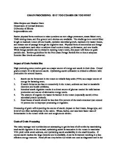
We have been seeing Icom IC-746PROs come in with a bad driver modules and/or driver idle bias current set far too high from the factory. Fig. 1, IC-746PRO driver module
R-11, Driver Unit Idle (resting) TX current adjustment INDICATIONS Low or no power output in all modes. Usually starts off as an intermittent, then gets worse with time. Also excessive current draw (4.5 to 5.5 amperes) in SSB-TX with mic gain set to zero. Excessive heating of the driver transistors; they immediately become too hot to touch upon going into TX mode, SSB, with no modulation. If your rig has NOT shown intermittent power problems yet, skip down to RESETTING THE IDLE BIAS CURRENT. We have had at least three 746PROs with driver modules that were installed without heat sink compound (Fig.1). In all three cases also the driver idle bias current setting was between 2.0 and 2.5 amperes. This is also as specified in the factory service manual (which we feel is incorrect).
COPYRIGHT 2007-2008 B&B TECHNICAL SERVICES. Neither the author nor B&B TECHNICAL SERVICES is responsible for damage to any electronic equipment from use of this information. Static control procedures and tools must be used in the execution of this work. If in doubt please enlist the help of a competent technician. Illegal operation of Amateur Radios is neither condoned nor encouraged by the author or by B&B TECHNICAL SERVICES. In case of error, omission or correction, contact the AUTHOR directly; do not contact the distributor of this information. All rights reserved. This document, in original, unedited condition may be distributed freely for personal use only.
Fig. 2, IC-746PRO with driver module removed; no heat sink compound
The factory-specified driver resting current of 2.5 amperes results in 35 watts of heat generated at 14.2 volts, to a heat sink surface of about than a square inch, with no compound. The driver FETs start to desolder themselves with every transmission. They become intermittent, with power output going away, coming back, half power, 1/4 power, etc. Finally they fail altogether. To repair, the driver module must be replaced. Resoldering the FETs will only prolong the agony and they will fail again. MODULE REPLACEMENT Icom part number is 98414749. Be prepared for a very long lead-time in some cases. To replace the module, a good professional-quality vacuum desoldering station must be used (no sucker bulbs). An alternative is the ChipQuik system (www.chipquik.com). We have used the Chipquik system extensively and it works just fine. When replacing the module, use heat sink compound on the back of the new module. Apply to only one surface and spread it thin; you don’t need much. Cover the heat sink bar completely however. Torque the screws down “just snug”
COPYRIGHT 2007-2008 B&B TECHNICAL SERVICES. Neither the author nor B&B TECHNICAL SERVICES is responsible for damage to any electronic equipment from use of this information. Static control procedures and tools must be used in the execution of this work. If in doubt please enlist the help of a competent technician. Illegal operation of Amateur Radios is neither condoned nor encouraged by the author or by B&B TECHNICAL SERVICES. In case of error, omission or correction, contact the AUTHOR directly; do not contact the distributor of this information. All rights reserved. This document, in original, unedited condition may be distributed freely for personal use only.
BEFORE soldering the pins, to reduce stress on the new module. Finish tightening the screws after resoldering the interboard connections to the new module. RESETTING THE IDLE BIAS CURRENT When either replacing the driver module, or adding life to one that has not been changed, the resting or idle bias current for the drivers must be reset. The factory service manual states this should be 2.5 amperes; we have found that 0.50 amperes is much better, resulting in only 6 watts of dissipated heat rather than 35 watts. Remove the rig top cover and internal final unit cover. Place a digital ammeter (such as the Fluke 70 series) in series with the power supply positive lead (you can break the cable at the fuse; most meters have an internal fuse in case something goes wrong). Turn on the rig and mark down your receive resting current (no speaker volume). RX RESTING CURRENT: ___________ AMPERES With dummy load connected, go into TX mode, SSB, no audio input. Mark down your TX resting current reading. TX RESTING CURRENT: _______________ AMPERES Locate R-11, the small blue potentiometer just to the left of the driver unit (refer to Fig. 1). Use an insulated tool to prevent accidental shorts. Turn the pot CCW (to the left) all the way. Mark down again your TX resting current reading. The difference between this reading and the previous reading is where the driver idle bias current was set. TX RESTING CURRENT, R-11 AT MIN (FULL CCW): ___________ AMPERES Next, turn R-11 slowly CW (to the right) and watch for the TX resting current to increase by 0.50 amperes. Allow the temperature of the drivers to stabilize the reading; reset as needed to attain 0.50 amperes of resting current for the drivers. COPYRIGHT 2007-2008 B&B TECHNICAL SERVICES. Neither the author nor B&B TECHNICAL SERVICES is responsible for damage to any electronic equipment from use of this information. Static control procedures and tools must be used in the execution of this work. If in doubt please enlist the help of a competent technician. Illegal operation of Amateur Radios is neither condoned nor encouraged by the author or by B&B TECHNICAL SERVICES. In case of error, omission or correction, contact the AUTHOR directly; do not contact the distributor of this information. All rights reserved. This document, in original, unedited condition may be distributed freely for personal use only.
Carefully check the driver transistor temperature with your fingers; they should be just warm to the touch, not overly hot. If you can leave your fingers on them without pain, that is good. NEW TX RESTING CURRENT: ________________ Double check: Subtract “R-11 AT MIN” reading from the “NEW TX RESTING CURRENT” reading; it should be very near 0.50 amperes. You can also set the HF final resting current to 300mA with R-18, which is shown at the very top center of Fig. 1, just behind the small toroid for the driver output. We have found that this setting is usually pretty close however and should not need adjustment. Use the same method as for the driver adjustment. VHF final resting current is set to 1.00 amperes with R204, which is located under the speaker; again, this is usually pretty close and should not require adjustment. Again, use the same method as before, writing down your readings. Please note that in both RX and TX, the 746 series is a bit of a current hog; battery operation over a contest weekend would require in excess of 400AH to make it all the way through, or a solar system to charge the batteries, hi! NOTES The new driver resting current setting was arrived at by using a close-by ham friend to check adjacent channels for splatter while adjusting at different bias current settings. When reducing from 2.5 amperes to 0.50 amperes, no additional third-order distortion was noted on the opposite sideband to that which was being transmitted with normal voice operation, compressor ON and set to about 10dB of compression. Check yours as needed after adjustment, prior to extensive use at the new setting. Some in the repair community feel that an additional heat sink on TOP of the drivers is needed; we have found however that after resetting the driver bias, and using heat sink compound on a new module, that generated heat on the drivers is quite reasonable even under full output power of 100 watts in FM or CW modes and an additional heat sink is probably not needed. If you have not replaced your COPYRIGHT 2007-2008 B&B TECHNICAL SERVICES. Neither the author nor B&B TECHNICAL SERVICES is responsible for damage to any electronic equipment from use of this information. Static control procedures and tools must be used in the execution of this work. If in doubt please enlist the help of a competent technician. Illegal operation of Amateur Radios is neither condoned nor encouraged by the author or by B&B TECHNICAL SERVICES. In case of error, omission or correction, contact the AUTHOR directly; do not contact the distributor of this information. All rights reserved. This document, in original, unedited condition may be distributed freely for personal use only.
module and instead found that only the idle bias needed to be reset, use the “finger test” to determine if you need to remove the module and place heat sink compound or not. If the drivers still become too hot to touch quickly after going into SSB TX mode with no audio input, then addition of heat sink compound or an external heat sink added to the top of the transistors may be useful. ADDTIONAL NOTE: Sometime around August 2007, Icom came out with some pretty extensive updates to the 746PRO final unit. One of the updates was to decrease the driver resting (idle) bias current from 2.5 amperes to 1.5 amperes. We have found however that 0.5 amperes is sufficient to keep third order distortion low, and still ensure cool operation of the drivers.
COPYRIGHT 2007-2008 B&B TECHNICAL SERVICES. Neither the author nor B&B TECHNICAL SERVICES is responsible for damage to any electronic equipment from use of this information. Static control procedures and tools must be used in the execution of this work. If in doubt please enlist the help of a competent technician. Illegal operation of Amateur Radios is neither condoned nor encouraged by the author or by B&B TECHNICAL SERVICES. In case of error, omission or correction, contact the AUTHOR directly; do not contact the distributor of this information. All rights reserved. This document, in original, unedited condition may be distributed freely for personal use only.