Ingeniería e Investigación vol. 36 n.° 1, april - 2016 (23-30) DOI: http://dx.doi.org/10.15446/ing.investig.v36n1.49253
Optimization of the linear quadratic regulator (LQR) control quarter car suspension system using genetic algorithm Optimización del regulador lineal cuadrático (LQR) del sistema de control de suspensión de coche usando el algoritmo genético M. P. Nagarkar1, and G. J. Vikhe2 ABSTRACT In this paper, a genetic algorithm (GA) based in an optimization approach is presented in order to search the optimum weighting matrix parameters of a linear quadratic regulator (LQR). A Macpherson strut quarter car suspension system is implemented for ride control application. Initially, the GA is implemented with the objective of minimizing root mean square (RMS) controller force. For single objective optimization, RMS controller force is reduced by 20.42 % with slight increase in RMS sprung mass acceleration. Trade-off is observed between controller force and sprung mass acceleration. Further, an analysis is extended to multi-objective optimization with objectives such as minimization of RMS controller force and RMS sprung mass acceleration and minimization of RMS controller force, RMS sprung mass acceleration and suspension space deflection. For multi-objective optimization, Pareto-front gives flexibility in order to choose the optimum solution as per designer’s need. Keywords: Genetic algorithm (GA), MacPherson strut, quarter car, linear quadratic regulator (LQR), optimization.
RESUMEN En este artículo se presenta un algoritmo genético (GA) basado en un enfoque de optimización con el fin de encontrar los parámetros de la matriz de ponderación del regulador lineal cuadrático (LQR). Se implementa un sistema de suspensión Macpherson para la aplicación del control de amortiguación. Inicialmente el GA se implementa con el objetivo de minimizar la raíz cuadrada media (RMS) del controlador de fuerza. Para la optimización de un único objetivo, el controlador RMS de la fuerza se reduce en un 20,42 % con un ligero aumento en la aceleración RMS de la masa suspendida. Se observa equilibrio entre el control de fuerza y la aceleración de la masa suspendida. Además, el análisis se extiende a la optimización multiobjetivo con objetivos como la minimización del control RMS de la fuerza y de la aceleración debida a la masa suspendida y la minimización del control RMS de la fuerza, RMS surgida por la aceleración de la masa y la deflexión del espacio de la suspensión. Para la optimización multiobjetivo el Pareto-frontal facilita elegir la solución óptima según la necesidad del diseñador. Palabras clave: Algoritmo genético (AG), suspensión MacPherson, cuarto de coche, regulador lineal cuadrático (LQR), optimización. Received: February 19th 2015 Accepted: June8th 2015
Introduction Automobile suspension systems have been widely applied to vehicles from horse drawn carriages with flexible leaf springs to modern automobiles. The primary function of the suspension system is to isolate the passengers from vibrations due to road unevenness. A passive suspension system consists of conventional springs and dampers with a fixed spring rate and damping parameters. It has conflicting requirements between ride comfort and vehicle handling. It has no mechanism of feedback control. The active suspension system replaces the classical passive elements by a controlled system, which can supply external force to the system (Fuller, 1996). Various mathematical models for suspension systems have been presented by researchers to ride and control applications. A 2 degrees of freedom (DoF) quarter car suspension system was implemented by various researchers(Yahaya et al.,2000; Elmadany and Al-Majed
2001; Assadian, 2002; Tueest et al., 2009; Darus and Enzai, 2010; Nekoui and Hadavi, 2010; Isamil et al., 2012). The suspension system is modeled as lumped masses and linear springs and dampers. In this study, a 2 DoF Macpherson strut suspension model is implemented for control application. M. P. Nagarkar: Masters in Mechanical Engineer, SCSM College of Engineering, India.PhD Dept., AVCoE, Sangamner, India. Email:
[email protected]. 2 G. J. VikhePatil: Principal, AVCoE, Sangamner, India. 1
How to cite: Nagarkar, M. P., & Vikhe, G. J. (2016). Optimization of the linear quadratic regulator (LQR) control quarter car suspension system using genetic algorithm. Ingeniería e Investigación, 36(1), 23-30. DOI: http://dx.doi.org/10.15446/ing.investig.v36n1.49253.
23
Optimization of the linear quadratic regulator (LQR) control quarter car suspension system using genetic algorithm
LQR control is an optimal control method with quadratic performance indexes. LQR is simple and can achieve closed loop optimal control with linear state feedback or output feedback. In designing an LQR controller, the selection of weighting matrices is a key issue which directly affects the control effort. An LQR problem is presented with full state feedback for suspension system. The weighting constants ql, q2, q3, and ρ, used to calculate matrices Q and R, were selected based on the designer’s preferences (Elamdany and Al-Majed, 2001). The LQR control scheme to control an actuator in an active suspension system was presented where the critical issue was to select the weight matrices which in turn determine the system performance. The values of weighting matrices were selected for simulation (Yahaya et al., 2000; Zhen et al., 2006). Yoon et al. had presented an application of optimal control law via an LQR control method for controlling altitude of the tri-rotor UAV. The system consists of a linearized analytical model of single tilt dynamics based on force and moment dynamics. To design an LQR control, a linearized model is assumed. In the designing process, Q and R matrices are chosen to regulate roll, pitch and yaw angles. Flight tests such as the hovering test, altitude test and yaw control tests are conducted. Authors had successfully demonstrated fast yaw control motion using LQR based attitude controller (Yoon et al., 2013). An approach to a LQR problem with an objective to translate the system’s performance objectives into the cost function parameters was presented (Oral et al., 2010). The selection of the elements of the performance index matrices, Q and R, was not carried out by trial and error but calculated for time domain design, which specifies steady and transient response of the system. The ratio between the weighting parameters was obtained using the mathematical relations. But, for minimum oscillations, the weighting parameters need to be adjusted.
of LQR controller so as to fulfill these requirements. The trial and error method or arbitrarily choosing the weight matrices is cumbersome and time consuming. Hence, the GA based search technique is implemented to search the optimum weight matrices parameters. Macpherson strut suspension system is simulated in Matlab/Simulink® environment. The output is fed to the optimization algorithm to determine objectives and check the constraints. This optimization process is iteratively repeated until optimization stopping criterion is reached. In this paper, number of generations is used as an optimization stopping criterion. For multiobjective optimization, trade-off front is obtained, which gives more flexibility to designers to choose solution.
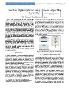
Macpherson Strut Quarter Car Model The Macpherson suspension was created by Earl Macpherson in 1949 for the Ford Company. This type of suspension is widely used in vehicles as it is compact size and light weight. A model of the Macpherson strut suspension with spindle properties developed by Hong et al.(1999) was implemented for ride control applications The schematic of a Macpherson strut suspension is shown in Figure 1. Equation of Motion for Macpherson Strut Model (16) (ms + mus )!! xs + mus lC cos(θ − θ0 )θ!! − mus lC sin(θ − θ0 )θ! 2 +kt (xs + lC (sin(θ − θ0 ) − sin(−θ0 ) − xr )) = 0
mus lC 2θ!! + mus lC cos(θ − θ0 )!! xs +
c p b12sin(α′ − θ0 )θ! 4(a1 − b1(cos(α′ − θ)) (1)
+kt lC cos(−θ0 )(xs + lC sin(θ − θ0 ) − sin(−θ0 )) − xr ⎤ ⎡ d1 1 ⎥ = −l F − ks sin(α′ − θ) ⎢⎢ b1 + B LQR 12 ⎥ ′ 2 (c1 − d1cos(α − θ) ) ⎥⎦ ⎢⎣
Either LQR weight matrices were arbitrarily chosen by the authors for ride control application (Yahaya et al., 2000; Zhen et al., 2006; Tusset et al. 2009; Darus and Enzai, 2010; Nekoui and Hadavi, 2010; Hsabullah and Faris, 2010; Ismail et al., 2012) or the weight matrices parameters of a LQR controller were adjusted by trial and error until desired performance was achieved (Oral et al., 2010). A LQR control of a 2 DoF Macpherson strut quarter car active suspension system is presented in this paper. The Genetic Algorithm search technique is implemented for optimum selection of weight matrices. Initially, minimization of RMS controller force objective is used for optimization. Minimum controller force means minimum energy expenditure. GA is implemented to search the optimum weighting matrices, Q and R, parameters. The study is further extended to multi-objective optimization. In multi-objective optimization, two objective functions are initially used viz. RMS controller force and RMS sprung mass acceleration. Minimization of RMS sprung mass acceleration leads to better ride comfort. Further, third objective function is added as suspension space. Due to multi-objective nature of LQR control action and objective are conflicting; the key issue is to select the weight matrices 24
Figure 1. Macpherson strut quarter car model (Hong et al. 1999)
Where ms and mus sprung mass and unsprung mass in kg, ks and kt suspension spring stiffness and tyre stiffness in N/m, cs suspension damping coefficient in Ns/m, xs , x! s , and x!!s sprung mass displacement in m, velocity in m/s and acceleration in m/s2 respectively, xr road roughness in m, lA, lB, and lC distance from O to A, O to B, control arm length in m respectively, θ and θ0 rotation angle of control arm and
Ingeniería e Investigación vol. 36 n.° 1, april - 2016 (23-30)
NAGARKAR, AND VIKHE
initial angular displacement of control arm, α angle made by link OA with horizontal, α′ = α + θ0
a1 = l A2 + lB 2
,
c1 = a12 − a1b1cos(α + θ0 )
,
b1 = 2l AlB
, d1 = a1b1 − b1 cos(α + θ0 ) 2
T
T
For linearization the state variables are ⎡⎣⎢ x1,x2 ,x3 ,x4 ⎤⎦⎥ = ⎡⎣⎢ xs , x! s ,θ,θ! ⎤⎦⎥ and output as x!!s . Linearization of Equation (1) is carried out at an equilibrium point (0,0, θ0,0)(Hong et al., 1999).
⎫⎪ ⎤ ⎪⎧⎪⎡ 1 ⎪⎪ ⎥ ⎪⎪⎢⎢ ( ms + mus ) ⎪⎪ ⎥ ⎪⎪⎢ 2 ⎥ ⎪⎪ ⎪⎪⎢ ⎥ d1 ⎪⎪ ⎥ ⎪⎪⎢ ks cosα′(b1+ ) ⎪⎪ 12 ⎢ ⎥ ′ 2 2 2 2 (c1 − d1cosα ) ⎪⎪⎪⎢ ⎥ . ⎡⎢ ms mus l C + mus l C sin (−θ0 )⎤⎥ ⎪⎪ ⎣ ⎦ ⎢ ⎥ 2 ⎪ ⎪⎪ −ms kt lC cos(−θ0 ) ′ ⎪ d sin α ⎢ ⎥ a43 = ⎨ 1 ⎬ 1 )⎥ ⎪⎪ (ms mus l 2 + m2 l 2 sin2 (−θ0 ))2 ⎪⎪⎢− ( ms + mus ) ks sinα′( 32 C us C 2(c1 − d1cosα′) ⎥ ⎪⎪⎢ 2 ⎪⎪ ⎥ ⎪⎪⎢⎢ ⎪⎪ 2 ⎥ ⎪⎪⎢⎣+ms kt lC cos(−θ0 ) ⎪⎪ ⎥⎦ ⎪⎪ ⎪⎪ d1 ⎪⎪ 1 ⎪⎪ 2 2 ⎪⎪+ 2 ( ms + mus ) mus ks lc sinα′sin(−θ0 )(b1+ (c − d cosα′)1 2 ) ⎪⎪ 1 1 ⎪⎩ ⎪⎭
a44 =
The linearization equation is (for details(Hong et al., 1999)): ! = Ax(t) + B1 f LQR (t) + B2 xr (t) x(t)
(2)
and output equation – y(t) = Cx(t) + D1 f LQR (t) + D2 xr (t)
(3)
where (A) is System matrix, and (B1),(B2) Control Input Matrix and Disturbance Matrix. ⎡ ⎢ ⎢ A = ⎢⎢ ⎢ ⎢ ⎢⎣
0 1 0 a21 0 a23 0 0 0 a41 0 a43
⎡ 0 ⎢ ⎢ ⎤ lB cos(−θ0 ) ⎢ 1 ⎥ ⎢ ms lC + mus lC sin2 (−θ0 ) a24 ⎥⎥ , ⎢ B1= ⎢ ⎥ ⎢ 0 1 ⎥ ⎢ ⎥ (ms + mus )lB ⎢ a44 ⎥ ⎢ ⎦ ⎢ ms mus lC 2 + mus 2lC 2sin2 (−θ0 ) ⎢⎣
⎡ 0 ⎢ ⎢ kt lC sin2 (−θ0 ) ⎢ ⎢ ms lC + mus lC sin2 (−θ0 ) ⎢ B2 = ⎢ ⎢ 0 ⎢ ⎢ ms kt lC cos(−θ0 ) ⎢ ⎢ ms mus lC 2 + mus 2lC 2sin2 (−θ0 ) ⎢⎣ ⎡ lB cos(−θ0 ) ⎢ D1= ⎢⎢ ms lC + mus lC sin2 (−θ0 ) ⎢ ⎢⎣ 0 a21 =
−kt lC sin2 (−θ0 )
ms lC + mus lC sin2 (−θ0 )
⎤ ⎥ ⎥ ⎥ ⎥ ⎡ a ⎥ ⎥ , C = ⎢⎢ 21 ⎥ ⎢⎣ 0 ⎥ ⎥ ⎥ ⎥ ⎥⎦
0
a23
0
1
⎤ ⎥ ⎥ ⎥ ⎥ ⎥, ⎥ ⎥ ⎥ ⎥ ⎥ ⎥ ⎥⎦
a24 =
cs b sin α′ 1 1 , . ms lC + mus lC sin2 (−θ0 ) 4(a1 − b1cosα′)
a41 =
−ms kt lC cos(−θ0 )
ms mus l 2 + m2 l 2 sin2 (−θ0 ) C
us C
.
LQR Controller The LQR problem is a regulator problem using a linear system with a quadratic cost function. The LQR is an optimal control method for the linear system. Let us consider the system described in Equation (2). Consider a state variable feedback regulator; f LQR = −K LQR x
(4)
The design procedure consists of determining the control input fLQR, which minimizes the performance index. The performance index JLQR represents the performance characteristic requirement as well as the controller input limitation (Anderson and Moore, 1990; Ogata, 2002). In LQR, the quadratic performance index is expressed as:
∞
J LQR = ∫ (x T Qx + uT Ru) dt
(5)
0
where matrices Q and R are positive-definite (or positivesemi definite) Hermitian or real symmetric matrices and are known as weighting matrices.
⎤ ⎥ ⎥ ⎥ ⎥ ⎥ ⎦
The first term on the right-hand side of the Equation (5) accounts for the error and second term accounts for the expenditure of the energy of the control signal. Matrices Q and R determine the relative importance of the error and expenditure of the performance index. (For details refer to (Ogata, 2002)).
⎤ ⎪⎫⎪ ⎪⎧⎪⎡ 1 d1 ⎥ ) ⎪⎪ ⎪⎪⎢⎢ ks (b1 + ⎥ (c1 − d1 cos(α′))1 2 ⎪⎪ ⎪⎪⎢ 2 ⎥ ⎪ ⎪⎪⎢ ⎥ ⎥ . ⎡ m l + m l sin2 (−θ )⎤ ⎪⎪⎪ ⎪⎪⎢(cos(α′ + θ ) − 1 (k sin α′ cos(−θ ) ⎥ ⎢⎣ s C 0 s 0 us C 0 ⎥⎦ ⎪ ⎪⎪⎢ 2 ⎪⎪ 1 ⎢ ⎥ a23 = ⎥ ⎬ ⎨⎪⎢ d12 sin α′ ⎪⎪ ⎥ 2 2 (ms lC + mus lC sin2 (−θ0 ))2 ⎪⎪⎢( ) − k l sin (−θ )cos(−θ ) ⎥ ⎪⎪ ⎪⎪⎢ t C 0 0 32 ′ 2(c − d cos α ) ⎢ ⎥ ⎪⎪ 1 ⎦ ⎪⎪⎪⎣ 1 ⎪⎪ d1 ⎪⎪ ⎪⎪⎪ 2 ′ +m k l sin α sin(−θ )cos (−θ )(b + ) ⎪⎪ 0 0 1 ⎪⎪⎪⎩ us s C (c1 − d1 cos α′)1 2 ⎪⎭
2
us C
where fLQR is the LQR control force in N, KLQR the state feedback gain matrix, and x the state vector.
,
2
C
a24 ⎤⎥ ⎥ 0 ⎥⎦
⎤ ⎡ kt lC sin2 (−θ0 ) ⎥ ⎢ ⎥, ⎢ ⎥ D2 = ⎢ ms lC + mus lC sin2 (−θ0 ) ⎥ ⎢ ⎥⎦ ⎢ 0 ⎣
(m + mus ) csb12sin2α′ −1 . s 2 2 2 4(a1 − b1cosα′) ms mus l + m l sin (−θ0 ) 2
Gain matrix KLQR, which minimizes JLQR is:
K LQR = R−1BT P
(6)
where P is the positive definite matrix.
Genetic Algorithm The genetic algorithm is an optimization and global search technique invented by Holland (1975, 1992). This technique uses the principle of genetics and natural selection. As random numbers are generated during the operation of genetic algorithms, GAs are stochastic algorithms. These random numbers generated determine the search result (Holland, 1975, 1992).
Ingeniería e Investigación vol. 36 n.° 1, april - 2016 (23-30)
25
Optimization of the linear quadratic regulator (LQR) control quarter car suspension system using genetic algorithm
Yang et al. presented a GA based hybrid method of optimization for constrained optimization. This hybrid method combines the chaotic initialization method, improved boundary simulation and the GA. Backward binary search was implemented in the improved boundary initialization method for feasible boundary region. Author, along with bench mark function, presented three engineering problems with single objective function along with constraints (Yang et al., 2013). However, the suspension control problem is of multi-objective nature with constraints. The GA method is described as follows: Population: The optimization process starts with an initial population or initial set also called as first generation. First generation is created by using random chosen designs. Selection: The objective function evaluates and then rates each solution in terms of fitness. All genes will be checked to satisfy design constraints. The fitness is numeric value represents the probability of survival. Selection is performed on the population by keeping the solutions with best fitness value. The genes having best fitness vales (i.e. minimum RMS LQR controller force or RMS sprung mass acceleration) are selected. The optimization algorithm is an iterative process. Using operators such as cross-over operator, mutation operator, new generation is created. Genes having better fitness are allowed to survive and carried forward in next generations. Algorithm steps are repeated till some convergence criterion or number of generations or fitness or CPU time is reached.
Hence, RMS sprung mass acceleration and maximum suspension travel are considered as objective functions for multi-objective optimization. RMS Sprung mass acceleration is expressed as:
aRMS =
∑
i=N i=1
N
ai2
Suspension space requirement is attained by minimizing the maximum travel of suspension. Suspension working space is the distance between the car body and the tire, Suspension Working Space = xs − xus
Nature of objective functions (like controller force, sprung mass acceleration and suspension space requirement) is conflicting, so multi-objective optimization using NGPM (Song, 2011, 2014) (A NSGA-II Program in Matlab) is carried out (Deb et al., 2002).
As per ISO 2631 (ISO, 1997), if RMS sprung mass acceleration is below 0.315 m/s2, passengers feel highly comfortable. At least 0.127 m of suspension travel is required and the maximum sprung mass acceleration should not increase 4.5 m/s2 so as to avoid hitting the suspension stops (Baumal et al., 1998). RMS sprung mass acceleration, maximum sprung mass acceleration and suspension travel are the constraints for optimization. The formulation of optimization problem is:
• Case I: Single objective optimization fobj = Minimize (RMS fLQR )
• Case II: Multi objective optimization (2 Objectives) fobj1 = Minimize (RMS fLQR )
• Case III: Multi objective optimization (3 Objectives) fobj1 = Minimize (RMS fLQR ) fobj2 = Minimize (RMS arms ) fobj3 = Minimize (max(Suspension Travel))
Problem Statement
Three optimization cases are subject to constraints:
The main weighting controller controller criterion.
arms ≤ 0,315m / s2 , max(Suspension Travel) ≤ 0,127m ,
objective of this paper is to search optimum parameters of Q and R matrices of a LQR to minimize the controller force. Hence RMS force is chosen as one of the optimization
RMS Controller Force – It is expressed as:
RMS FLQR =
∑
i=1
N
2 FLQR
i
(7)
where N is the number of sample points. While designing a suspension system, performance parameters which are under considerations are ride comfort, suspension travel (or rattle space). The ride comfort is characterized by the RMS sprung mass acceleration, and the suspension travel is characterized by the relative travel between sprung mass and unsprung mass.
26
(9)
fobj2 = Minimize (RMS arms )
Multi-Objective Optimization
i=N
(8)
arms ≤ 4,5m / s2
Genetic Algorithm Parameters Population: 100, Generations: 100, Selection: Tournament Mutation: 0.5 %, Crossover fraction: 55 %,Crossover: Single point
Search Space for Q and R Matrices Depending upon the weight matrices Q and R, the system will exhibit a different response. The selection of larger values of Q, to keep small JLQR, will result in smaller values of state x and thus state decays faster to zero (Levine W, 2010).
Ingeniería e Investigación vol. 36 n.° 1, april - 2016 (23-30)
NAGARKAR, AND VIKHE
1009 ≤ Q11 ≤ 1011, 103 ≤ Q22 ≤ 106, 10-2 ≤ Q33 ≤ 101,
10 ≤ Q44 ≤ 10 , 10 ≤ R1 ≤ 10 -2
1
-3
-1
Results and Discussions The LQR controller and GA based LQR controllers are simulated in Matlab® environment. Quarter car parameters: ms = 453 kg
mus = 71 kg
ks = 17658 N/m
cs = 1950 N.sec/m kt = 183887 N/m
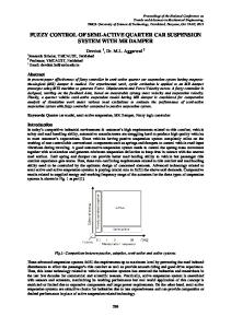
lA = 0.66 m, lB = 0.34 m, lC = 0.37 m, α = 74˚, θ0 = -2˚ Input road condition is modeled as class E road. Refer to Figure 2.
Figure 2. Road profile (Class E, Velocity 80 kmph)
The degree of road roughness is 4096 × 10-6 m2/(cycle/m) (Zhang et al., 2007). The Vehicle is travelling with a speed of 80 km/h.
Single Objective Optimization The primary objective of controller design is to minimize the controller force by searching optimum weighting parameters of a LQR controller using GA. This is attained by minimizing the RMS value of controller force, which leads to a lower amount of controller force supplied to the active suspension system in order to minimize acceleration values experienced by the passengers. The RMS value of controller force is 76.4657 N. The convergence of objective function is shown in Figure 3. RMS controller force is observed to be constant after the 40th generation. From Figure 4 and Table 1, for single objective optimization, RMS controller force is reduced by 20.42 %, whereas a slight increase in RMS sprung mass acceleration is observed (3.65 %) when compared to an un-optimized LQR controller.
Figure 4. Quarter car response for single objective optimization
Multi Objective Optimization The vehicle active suspension system has to fulfill some conflicting criterion such as minimum controller force, ride comfort and suspension space requirement. Ride comfort is attained by minimizing the RMS sprung mass acceleration. The following cases of multi-objective optimization are studied: RMS controller force and RMS sprung mass acceleration. RMS controller force and RMS sprung mass acceleration and maximum suspension working space. Figure 5 shows the pareto front of multi-objective optimization of RMS controller force and RMS sprung mass acceleration. The pareto front has the concave portion. The trade-off between controller force and sprung mass acceleration can be clearly observed in Figure 5. In this situation the designer has to make the decision of selecting final values of weighting matrices. For multi-objective optimization, there are three cases of example. Cases I, II and III, as shown in Figure 5, are selected to be studied. Figure 6 shows sprung mass acceleration, suspension space and controller force for Cases I, II and III.
Figure 3. RMS controller force at each generation (Population: 100).
From Figure 6 and Table 1, regarding Case I, the RMS controller force is decreased by 19.6 % and the maximum controller force is also reduced by 17.8 %, while a slight
Ingeniería e Investigación vol. 36 n.° 1, april - 2016 (23-30)
27
Optimization of the linear quadratic regulator (LQR) control quarter car suspension system using genetic algorithm
increase in RMS sprung mass acceleration (3.5 %) is observed when compared to an un-optimized LQR controller. For Case II, the RMS controller force is increased by 158.95 %, while the RMS sprung mass acceleration is reduced by 33 %. In Case III, the RMS sprung mass acceleration is reduced by 55.38 % whereas the RMS controller force is increased by 395.21 %.Due to trade-off, it is the designer’s decision to choose parameters as per requirement.
A multi-objective optimization problem was converted into an uni-objective optimization problem using normalization. During simulation the vehicle was travelling over a class B road at 20 kmph speed. A sprung mass acceleration of 0.3326 m/ s2 and suspension space travel of 0.354843m was observed using SA optimized LQR control (Meng et al., 2014).
Figure 5. Pareto front – Two objectives.
Figure 7 shows the pareto front of multi-objective optimization of RMS controller force, RMS sprung mass acceleration and maximum suspension space requirement. In this type of multi-objective optimization, there are three cases of example. Cases IV, V and VI, as shown in Figure 7, are selected to be studied. Figure 8 shows controller force, sprung mass acceleration and suspension space for Cases IV, V and VI.
Figure 6. Response of quarter car model to Case I, II and III.
From Figure 8 and Table 1, for Case IV,the RMS controller force is decreased by 18.77 %, while a slight increase in RMS sprung mass acceleration (3.29 %) and a slight decrease in maximum suspension space deflection (3.53 %) is observed when compared to an un-optimized LQR controller. For Case V, the RMS controller force is increased by 145.16 % while the RMS sprung mass acceleration is reduced by 31.22 % and the maximum suspension space deflection is increased by 51.41 %. In Case VI, the RMS sprung mass acceleration is reduced by 56.11 %, whereas the RMS controller force is increased by 405.66 % and the maximum suspension space deflection is increased by 98.23 %. A trade-off is observed between controller force and sprung mass acceleration and suspension space deflection. It is the designer’s decision to choose parameters as per requirement. An optimal control of a linear 2 DoF vehicle suspension based on a simulated annealing (SA) optimization algorithm was presented by Meng et al. The LQR control weight matrices were searched using vertical acceleration of sprung mass, suspension space displacement and tyre displacement as objective functions. 28
Figure 7. Pareto front -Three objectives.
A current GA based optimization technique incorporates multi-objective optimization. Current paper discusses optimization using Macpherson strut quarter car model travelling over class E road at 80 kmph speed. For validation,
Ingeniería e Investigación vol. 36 n.° 1, april - 2016 (23-30)
NAGARKAR, AND VIKHE
the GA optimized LQR control is compared with unoptimized LQR control. In multi-objective optimization, for Cases III and VI, an RMS sprung mass acceleration of 0.1355 and 0.1333 m/s2 is observed, respectively, which is less than 0.3326 m/s2 obtained by SA. In GA, a population of 100 genes is used; hence, a pareto front of 100 different solutions is obtained, which gives designers more flexibility. Additionally, GA is successfully implemented for a single objective, two objective and three objective optimization, thus showing robustness.
Conclusion The work presents optimization of weighting matrices of the LQR controller. A Macpherson strut quarter car suspension model is used for control application. 1. Instead of trial and error or adjusting the weighting matrix parameters of the LQR controller, a GA based method is proposed to determine the parameters to set an objective or objectives. 2. Single objective optimization is successfully achieved using GA optimization to minimize the controller force. In single objective optimization, the controller force is reduced by 20.42 % with slight increase of 3.65 % in sprung mass acceleration. 3. Multi-objective optimization with two objectives and three objectives has been successfully implemented to search for optimum weighting parameters of the LQR controller. 4. Multi-objective optimization with two objectives, RMS controller force and RMS sprung mass acceleration, is successfully implemented using GA. Cases I, II and III are studied from pareto front. A trade-off is observed between controller force and sprung mass acceleration. In this case the designer generally chooses Case-II, which lies in the central region of the pareto front. 5. GA optimization with three objectives i.e. RMS controller force, RMS sprung mass acceleration and maximum deflection of suspension space is implemented using GA. Three cases, viz. IV, V and VI, are studied from pareto front. A trade-off is observed between controller force and sprung mass acceleration and suspension space requirements.
Figure 8. Response of quarter car model to Case IV, V and VI.
6. In multi-objective optimization, as per the requirement, the designer has greater flexibility to choose the solution from the sets of solution from the pareto front.
References
Table 1. Response of LQR and GA based LQR controller
Optimization Type
RMS FLQR (N)
Fmax (N)
aRMS (N/m2)
amax (N/m2)
Suspension Space Deflection (m)
Un-optimized
96.0892
323.5891
0.3037
0.9146
0.0085
Single objective
76.4657
263.4127
0.3148
0.9974
0.0083
Case I
77.2579
265.9790
0.3144
0.9941
0.0083
Case II
248.8203
716.5896
0.2033
0.5678
0.0131
Case III
475.8472
1289.662
0.1355
0.3685
0.0166
Case IV
78.0496
268.3454
0.3137
0.9905
0.00828
Case V
235.5755
684.2633
0.2089
0.5841
0.01287
Case VI
485.8867
1313.626
0.1333
0.3632
0.01685
Anderson,B. and Moore,J. (1990). Optimal control: linear quadratic methods. NJ: Prentice Hall. Assadian,F. (2002)A comparative study of optimal linear controllers for vibration suppression. Journal of the Franklin Institute, 339,347–360. DOI: 10.1016/S0016-0032(01)00050-3. Baumal,A.E., McPhee,J.J. and Calamai,P.H. (1998). Application of genetic algorithms to the design optimization of an active vehicle suspension system. Computer Methods in Applied Mechanics and Engineering, 163, 87-94. DOI: 10.1016/S0045-7825(98)00004-8. Darus, R. and Enzai, N.I. (2010) Modeling and Control Active Suspension System for a Quarter Car Model. Proceedings of CSSR 2010, 1203-1206. DOI: 10.1109/CSSR.2010.5773718. Deb,K., Pratap,A., Agarwal,S. and Meyarivan,T. (2002). A Fast and Elitist Multiobjective Genetic Algorithm: NSGA-II. IEEE
Ingeniería e Investigación vol. 36 n.° 1, april - 2016 (23-30)
29
Optimization of the linear quadratic regulator (LQR) control quarter car suspension system using genetic algorithm
Transactions on Evolutionary Computation, 6(2), 182-197, 2002. DOI:10.1109/4235.996017.
Ogata, K. (2002). Modern Control Engineering. New Delhi: Prentice Hall.
Elmadany,M. and Al-Majed,M. (2001).Quadratic Synthesis of Active Controls for a Quarter-Car Model. Journal of Vibration and Control, 7, 1237-1252. DOI: 10.1177/107754630100700806
Oral, Ö. Çetin,L., Uyar,E. (2010). A novel method on selection of Q & R matrices in the theory of optimal control. International Journal of Systems Control,, 1(2), 84-92.
Fuller, C. R., Elliott, S.J.and Nelson, P.A. (1996). Journal of Vibration and Control. London: Academic Press London. Hasbullah,F. and Faris,W. (2010). A comparative Analysis of LQR and Fuzzy Logic Controller for Active Suspension Using Half Car Model, Proceedings of 11th Int. Conf. Control, Automation, Ro-botics and Vision, 2416-2420. DOI:10.1109/ICARCV.2010.5707260. Holland,J.H. (1975). Adaptation in Natural and Artificial Systems. University of Michigan Press. Holland,J.H. (1992). Genetic Algorithms.Scientific American, Genetic Algorithms. Hong,K.S., Jeon,D.S., Yoo,W.S., Sunwoo,H., Shin,S.Y., Kim,C.M. and Park,B.S. (1999). A New Model and an Optimal Pole-Placement Control of the Macpherson Suspension System. SAE Technical Pa-per 1999-01-1331, 1-10. DOI:10.4271/1999-01-1331. Ismail,M., Peng,K., Hamzah,N., Sam,Y., Aripin, M., and Hasan,M. (2012). A Linear Model of Quarter Car Active Suspension System Using Composite Nonlinear Feedback Control. Proceedings of IEEE Student Conference on Research and Development, 98-103. DOI:10.1109/SCOReD.2012.6518619. ISO: 2631-1. (1997). Mechanical vibration and shock - Evaluation of human exposure to whole-body vibration. Levine, W. (2010). The control handbook. CRC Press. Meng, J., Chen, Q., and He, R. (2014). Research on optimal control for the vehicle suspension based on simulated annealing algorithm. Journal of Applied Mathematics, 2014, 1-5. Nekoui,M. and Hadavi, P. (2010). Optimal Control of an Active Suspension System. Proceedings of 14th EPE-PEMC, T560-T5-63. DOI:10.1109/EPEPEMC.2010.5606776.
30
Song,L. NGPM-A NSGA-II. (2011). Program in Matlab. User Manual. Version 4.1, pp. 1-20. Song,L. NGPM-A NSGA-II. (2014). Program in Matlab v14. Matlab Code. http://www.mathworks.com/matlabcentral/ fileexchange. Accessed 14 January 2014. Tusset, A., Rafikov,M., Balthazar,J. (2009). An Intelligent Controller Design for Magnetorheological Damper Based on a Quarter-car Model. Journal of Vibration and Control, 15(12), 1970-1920. DOI:10.1177/1077546309102677. Yahaya,M.S., Ruddin,M., Ghani,A. and Ahmad, N. (2000). LQR Controller for Active Car Suspension. Proceedings of TENCON, 441-444. DOI:10.1109/TENCON.2000.893707. Yang, J., Gao, H. and Lui, W. (2015). Hybrid Method of Chaotic Genetic Algorithm and Boundary Simulation for Constrained Optimization. International Journal of Innovative Computing, Information and Control, 11(3), 1059-1073. Yoon, S., Lee, S., Lee, B., Kim, C., Lee, Y., and Sung, S. (2013). Design and Flight Test of a Small Tri-Rotor Unmanned Vehicle with a LQR Based Onboard Attitude Control System. International Journal of Innovative Computing, Information and Control, 9(6), 2347-2360. Zhang,Y., Chen,W., Chen,L. and Shangguan,W. (2007). Non-stationary Random Vibration Analysis of Vehicle with Fractional Damping. Proceedings of 13th National Conference on Mecha-nisms and Machines (NaCoMM07), 171-178. Zhen,L., Luo, C. and Hu,D. (2006). Active Suspension Control Design Using a Combination of LQR and Backstepping. Proceedings of the 25th Chinese Control Conference, 123125. DOI:10.1109/CHICC.2006280612.
Ingeniería e Investigación vol. 36 n.° 1, april - 2016 (23-30)