Chapter 14
Ocean thermal energy conversion (OTEC)
14.1 Introduction The ocean is the world’s largest solar collector. In tropical seas, temperature differences of about 20−25 �C may occur between the warm, solar-absorbing near-surface water and the cooler 500–1000 m depth ‘deep’ water at and below the thermocline. Subject to the laws and practicalities of thermodynamics, heat engines can operate from this temperature difference across this huge heat store. The term ocean thermal energy conversion (OTEC) refers to the conversion of some of this thermal energy into useful work for electricity generation. Given sufficient scale of efficient equipment, electricity power generation could be sustained day and night at 200 kWe from 2 access to about 1 km of tropical sea, equivalent to 0.07% of the solar input. Pumping rates are about 6 m3 s−1 of water per MWe electricity production. The technology for energy extraction is similar to that used for energy efficiency improvement in industry with large flows of heated discharge, but on a much larger scale. The attractiveness of OTEC is the seemingly limitless energy of the hotter surface water in relation to the colder deep water and its potential for constant, base load, extraction. However, the temperature difference is very small and so the efficiency of any device for transforming this thermal energy to mechanical power will also be very small. Even for heating, warm seawater cannot be spilt on land due to its high salt content. Moreover, large volumes of seawater need to be pumped, so reducing the net energy generated and requiring large pipes and heat exchangers. There have been hundreds of paper studies, and a few experimental demonstration plants, with the first as far back as 1930. These were mostly resourced from France (pre-1970s) and then the USA, Japan and Taiwan in the 1980s, but less activity since then; see Avery and Wu (1994) for a detailed history. This experience confirmed that the cost per unit of power output would be large, except perhaps on a very large scale, and led to other justifications for pumping up the cold, deeper waters, which contain nutrients and therefore increase surface photosynthesis of phytoplankton and hence fish population. It now appears that OTEC could be at best a
454
Ocean thermal energy conversion (OTEC)
secondary aspect of systems for deep-water nutrient enrichment for marine fisheries, for cooling buildings or for desalination (see Section 14.5). Such integrated technology is called Deep Ocean Water Application (DOWA).
14.2 Principles Figure 14.1 outlines a system for OTEC. In essence it is a heat engine with a low boiling point ‘working fluid’, e.g. ammonia, operating between the ‘cold’ temperature Tc of the water pumped up from substantial depth and the ‘hot’ temperature, Th = Tc + �T , of the surface water. The working fluid circulates in a closed cycle, accepting heat from the warm water and discharging it to the cold water through heat exchangers. As the fluid expands, it drives a turbine, which in turn drives an electricity generator. The working fluid is cooled by the cold water, and the cycle continues. Alternative ‘open cycle’ systems have seawater as the working fluid, but this is not recycled but condensed, perhaps for distilled ‘fresh’ water; the thermodynamic principles of the open cycle are similar to the closed cycle. In an idealised system with perfect heat exchangers, volume flow Q of warm water passes into the system at temperature Th and leaves at Tc (the cold water temperature of lower depths). The power given up from the warm water in such an ideal system is P0 = �cQ�T
(14.1)
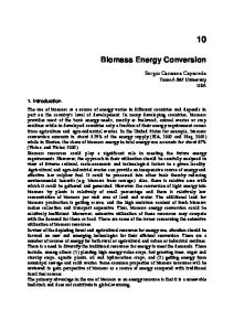
Figure 14.1 Schematic diagram of an OTEC system. A heat engine operates between the warm water from the ocean surface and the cold water from the ocean depths.
14.2 Principles
455
where �T = Th − Tc The second law of thermodynamics dictates that the maximum output of work energy E1 obtainable from the heat input E0 is E1 = �Carnot E0
(14.2)
Naively forgetting time dependence and the practicalities of heat exchangers, this is usually also given as P1 = �Carnot P0
(14.3)
where �Carnot = �T/Th
(14.4)
is the efficiency of an ideal Carnot engine operating at an infinitely slow rate between Th and Tc = Th − �T . With �T only ∼20 �C �=20 K�, even this ideal Carnot efficiency is very small, ∼7%. In practice, we cannot wait an infinite time for ideal thermal processes, so no practical system ever reaches Carnot efficiencies or a perfect heat exchange. So allowing for temperature drops of ∼5 �C across each heat exchanger and for the internal power for pumping, the efficiency of a real system will be substantially less at about 2–3%. Nevertheless these equations suffice to illustrate the promise and limitations of OTEC. From (14.1)–(14.4) the ideal mechanical output power is P1 = ��cQ/Th ���T�2
(14.5)
Example 14.1 Required flow rate For �T = 20�C the flow rate required to yield 1.0 MW from an ideal heat engine is (from (14.5)) Q1 =
�106 J s−1 ��300 K� −3
�103 kg m ��4�2 × 10³ J kg
−1
K−1 ��20 K�2
= 0�18 m3 s−1 = 650 t h
−1
Example 14.1 shows that a substantial flow is required to give a reasonable output, even at the largest �T available in any of the world’s oceans. Such a system requires large, and therefore expensive, machinery.
456
Ocean thermal energy conversion (OTEC)
Figure 14.2 Seasonal average of temperature difference �T between sea surface and a depth of 1000 m. Zones with �T ≥ 20�C are most suitable for OTEC. These zones all lie in the tropics. Source: US Department of Energy.
Since P1 depends quadratically on �T , experience shows that only sites with �T ≥ 20�C may possibly be economic. Figure 14.2 indicates that such sites are confined to the tropics, and Figure 14.3 suggests that the cold water has to come from a depth >∼400 m. Sites investigated include Hawaii (20�N, 160�W), Nauru (0�S, 166�E) and the Gulf Stream off Florida (30�N, 80�E). Tropical sites have the added advantage that both Th and Tc have little seasonal variation, so the potential output of the system is constant through the year.
14.2 Principles
457
Figure 14.3 Ocean conditions offshore from the island of Nauru, in the Central Pacific Ocean (0�S, 166 � E). (a) Water temperature. (b) Cross-section of sea bottom. The water temperatures are typical of those at good OTEC sites, and the steeply sloping sea floor allows a land-based system. Data from Tokyo Electric Power Services Co. Ltd.
Indeed steadiness and independence of the vagaries of weather are major advantages of OTEC as a renewable source of energy. Its other major advantages as a possible technology are: 1 2
At a suitable site, the resource is essentially limited only by the size of the machinery. The machinery to exploit it economically requires only marginal improvements in such well-tried engineering devices as heat exchangers and turbines. No dramatically new or physically impossible devices are required.
The major disadvantages are cost and scale. Even if the ideal power P1 of (14.5) was obtainable, the costs per unit output would be large, but resistances to the flow of heat and to fluid motion reduce the useful output considerably and therefore increase unit costs. Sections 14.3 and 14.4 estimate the energy losses due to imperfect heat exchangers and pipe friction. The installed costs of the best experimental OTEC plants (1980s to 1990s) were as large as $40 000 per kWe of electricity capacity, in comparison with about $1000 per kWe for conventional generating capacity in remote areas. However, the theory of Sections 14.2 to 14.4 suggests that even larger systems would be more economical, which maintains interest in OTEC. However, a large scale-up in a single step from small demonstration plants is imprudent engineering and therefore difficult to finance. Factors increasing the cost of offshore OTEC are maintenance at sea and submarine cabling, as discussed further in Section 14.5. However, there are a few especially favourable coastal sites where the sea bed slopes down so steeply that all the machinery can be placed on dry land. The island of
458
Ocean thermal energy conversion (OTEC)
Figure 14.4 Experimental land–based OTEC plant on Nauru, built by Tokyo Electric Power Services Company in 1981 for research. It was a ‘closed cycle’ system, rated at 100 kWe output. On the photograph the vertical framework to the rear contains the condenser, the nearer large horizontal cylinder is the evaporator, the turbine house is at the left, the cold water pipe runs out to sea (in the background), and cylinders in the foreground contain spare working fluid.
Nauru in the South Pacific has such topography. Figure 14.3 shows a section of the sea bottom there, and Figure 14.4 is a photograph of an experimental OTEC installation on the shore. Experience showed (i) the beach and submarine pipes must be buried or fixed extremely well to survive wave current forces, (ii) biofouling could be mitigated by 24-hourly pulses of chlorination, and (iii) in the pipes, both thermal losses and friction decreased efficiency significantly.
14.3 Heat exchangers These need to be relatively large to provide sufficient area for heat transfer at low temperature difference, and are therefore expensive (perhaps 50% of total costs). In calculating the ideal output power P1 as calculated in (14.5), we have assumed perfect heat transfer between the ocean waters and the working fluid. In practice, there is significant thermal resistance, even with the best available heat exchangers and with chemical ‘cleaning’ to lessen internal biofouling.
14.3 Heat exchangers 459
14.3.1 General analysis A heat exchanger transfers heat from one fluid to another, while keeping the fluids apart. Many different designs are described in engineering handbooks, but a typical and common type is the shell-and-tube design (Figure 14.5). Water flows one way through the tubes while the working fluid flows through the shell around the tubes. Figure 14.6 shows some of the resistances to heat transfer. The most fundamental of these arises from the relatively small thermal conductivity of water. As in Section 3.4, one can think of heat being carried by blobs of water to within a fraction of a millimetre of the metal surface, but, even with clean surfaces, the last transfer from liquid to solid has to be by pure conduction through effectively still water. Similarly the heat flow through both the metal and the adhering scum and biological growth is by pure conduction. A temperature difference �T is required to drive the heat flow across these conductive resistances. Let Pwf be the heat flow from water (w) to working fluid (f). Then Pwf = �T/Rwf
(14.6)
where Rwf is the thermal resistance between water and fluid. If it is assumed that there will be a similar temperature drop �T in the other heat exchanger,
Figure 14.5 Shell-and-tube heat exchanger (cut-away view).
Figure 14.6 Resistances to heat flow across a heat exchanger wall.
460
Ocean thermal energy conversion (OTEC)
the temperature difference actually available to drive the heat engine is not �T but �2 T = �T − 2�T
(14.7)
With an idealised Carnot engine the mechanical power output would be � � �T − 2�T �T P2 = (14.8) Th Rwf Equation (14.8) implies that �T/Rwf should be large to increase output power. Yet �T must be small to obtain maximum engine efficiency, so it is crucial to minimise the transfer resistance Rwf by making the heat exchanger as efficient as possible. Therefore the tubes must be made of metal (good conductor) and there must be many of them, perhaps hundreds, to provide a large total surface area. Other refinements may include fins or porous surfaces on the tubes, and baffles within the flow. With such an elaborate construction, it is not surprising that the heat exchangers constitute one of the major expenses of an OTEC system. This is the more so since the tube material has to be resistant to corrosion by seawater and the working fluid, all joints must be leakproof and all pipes capable of internal cleaning. The overall thermal resistance can be analysed in terms of the thermal resistivity of unit area rwf and the total wall area Awf , as in Section 3.6: Rwf = rwf /Awf
(14.9)
Much of the development work in OTEC concerns improvements in the design of existing heat exchangers. The aim is to decrease rwf , and thereby decrease the area Awf . Having smaller heat exchangers with less metal can lead to substantial cost reductions. Values for rwf of 3 × 10⁻⁴ m2 KW−1 (i.e. h = 1/r = 3000 W m−2 K−1 ) can be obtained by the best of existing technology. The flow rate required through the heat exchanger is determined by the power Pwf removed from the water, and by the heat transfers and temperatures involved. These are indicated in Figure 14.7, which shows a counterflow heat exchanger on each side of the working fluid circuit. At each point along the heat exchanger, the temperature difference between the working fluid and the water is �T . Thus the hottest point in the working fluid is at �in�
Thf = Thw − T and the coldest is at �in� Tcf = Tcw + T
Therefore the power given up by the hot water is � � �in� �out� Pwf = �cQ Thw − Thw
(14.10)
14.3 Heat exchangers 461
Figure 14.7 Temperatures and heat flows in the OTEC system of Example 14.2. The �in� �in� other quantities are calculated from Tcw , Thw , �T, P2 .
with the temperature drop �in�
�out�
Thw − Thw = �T − 2 T
(14.11)
14.3.2 Size Example 14.2 Heat exchanger dimensions Find a set of working dimensions for a shell-and-tube heat exchanger suitable for an OTEC system set to produce 1 MW. Assume a Carnot cycle for the working fluid, but allow for temperature reductions in non-perfect heat exchangers. Assume rwf = 3 × 10⁻⁴ m2 K W−1 , �T = 20 �C, �T = 4 �C, etc. as in Figure 14.7. Solution 1
Surface area From (14.9), Awf = rwf /Rwf From (14.8), 1/Rwf =
P 2 Th ��T − 2 T � T
462
Ocean thermal energy conversion (OTEC)
so Awf =
�1 × 10⁶ W��300 K��3 × 10⁻⁴ m2 K W−1 � �20 − 8� K�4 K�
= 1�9 × 10³ m2 2
This is a very large area of transfer surface. Flow rate For the parameters of Figure 14.7, �carnot =
�21 − 9��C 12 = �273 + 21� K 294
Pwf = P2 /�carnot = �1 MW��294/12� = 25 MW Therefore, from (14.10), and (14.11), the flow rate is Q=
�25 × 106 W� −3
−1
�103 kg m ��4�2 × 10³ J K−1 kg ��12 K�
= 0�50 m3 s−1 3
Thermal resistance of the boundary layers We suppose that each fluid boundary layer of Figure 14.6 contributes about half of rwf . In particular, assume that the thermal resistivity of the boundary layer (of water) on the inside of the pipe is given by rv = 1�5 × 10⁻⁴ m2 K W−1 Let d be the diameter of each tube in the heat exchanger. The convective heat transfer to the inside wall of a smooth tube is given by (C.14), see Section 3.4: � = 0�027�0�8 � 0�33 By definition of the Nusselt number, � = d/�rv k�. Thus the Reynolds number in each tube is � = d/�0�027rv k� 0�33 ��1�25 = �0�027��0�6 W m−1 K−1 ��7�0�0�33 �−1�25 �d/rv �1�25 = ad1�25 where a = 4�67 × 106 m−1�25 and the properties of water are from Appendix B.
14.3 Heat exchangers 463
4
Diameter of tube As an initial estimate, suppose d = 0�02 m. Then � = 3�5 × 10⁴ . Hence, flow speed in each tube is d �3�5 × 10⁴ ��1�0 × 10−6 m2 s−1 � = = 1�7 m s−1 �0�02 m�
u=�
Since the total flow through n tubes is Q = nu d2 /4 the number of tubes required is n=
�0�50 m3 s−1 ��4� �1�7 m s−1 ��3�14��0�01 m�2
= 3600 5
Length of tubes To make up the required transfer area A = n dl, each tube must have length l=
�1�9 × 10³ m2 � = 32 m �3600� �0�02 m�
This example makes it clear that large heat exchangers, with substantial construction costs, are required for OTEC systems. Indeed the example underestimates the size involved because it does not allow for imperfections in the heat engines etc., which increase the required Q to achieve the same power output. Also the example assumes that the pipe is clean and smooth. 14.3.3 Biofouling The inside of the pipe is vulnerable to encrustation by marine organisms, which will increase the resistance to heat flow (Figure 14.6), and thereby reduce the performance. Such biofouling is one of the major problems in OTEC design, since increasing the surface area available for heat transfer also increases the opportunity for organisms to attach themselves. Among the methods tried to keep this fouling under control are mechanical cleaning by continual circulation of close fitting balls and chemical cleaning by additives to the water. The effect of all these complications is that the need for cost saving encourages the use of components working at less than optimal performance, e.g. undersized heat exchangers.
464
Ocean thermal energy conversion (OTEC)
14.4 Pumping requirements Work is required to move large quantities of hot water, cold water and working fluid around the system against friction. This will have to be supplied from the gross power output of the OTEC system, i.e. it constitutes yet another loss of energy from the ambient flow P0 . Example 14.3 shows how the work may be estimated numerically using the methods of Section 2.6, although analytic calculations are difficult. The effect of cooling the water in the hydrostatic ‘circuit’ is small, but does encourage circulation.
Example 14.3 Friction in the cold water pipe The OTEC system of Example 14.2 (Figure 14.7) with P2 = 1 MW� �T = 20 �C has a cold water pipe with L = 1000 m, diameter D = 1 m. Calculate the power required to pump water up the pipe. Solution The mean speed is u = Q/A =
�0�50 m3 s−1 � = 6�3 m s−1
�0�5 m�2
Therefore the Reynolds number is uD v �0�63 m s−1 ��1 m� = = 6�3 × 10⁵ �1�0 × 10−6 m2 s−1 �
R=
In practice, many varieties of marine organisms brought up from the depths will adhere to the pipe, giving an equivalent roughness height � ∼ 20 mm, i.e. �/D = 0�02. Thus, from Figure 2.6, the pipe friction coefficient is f = 0�012 From (2.14), the head loss is Hf = 2fLu2 /Dg = 1�0 m To overcome this requires the same power as to lift a mass �Q per second through a height Hf , i.e. Pf = �QgHf = 4�7 kW
14.5 Other practical considerations 465
From Example 14.3, we see that the cold water pipe can be built large enough to avoid major friction problems. However, because the head loss varies as �diameter�−5 (See problem 2.6), friction loss can become appreciable in the smaller piping between the cold water pipe and the heat exchanger, and in the heat exchanger itself. Indeed, because the same turbulence carries both heat and momentum from the heat exchanger surfaces, all attempts to increase heat transfer by increasing the surface area necessarily increase fluid friction in the heat exchangers. In addition, the flow rate required in practice to yield a given output power is greater than that calculated in Example 14.2, because a real heat engine is less efficient than a Carnot engine in converting the input heat into work. This increases the power lost to fluid friction. Fouling of the heat exchanger tubes makes the situation worse, both by further raising the Q required to yield a certain power output, and by decreasing the tube diameter. As a result, in some systems over 50% of the input power may be lost to fluid friction. Power used by the pumps themselves is another ‘loss’ from the output power.
14.5 Other practical considerations The calculations of the previous sections confirm that there are no fundamental thermodynamic difficulties that prevent an OTEC system from working successfully. Although there remain a number of practical, engineering and environmental difficulties, we shall see that none of these appears insuperable from a technical point of view. 14.5.1 The platform American designers drew up conceptual plans for large systems, generating electricity at about 400 MWe , based on a large floating offshore platform, similar to those used in oil drilling. Since such a platform would be heavy and unwieldy, there would be a major problem in connecting it to the cold water pipe (CWP), because of the stresses from surface waves and currents. One response to this problem is to make the platform neutrally buoyant and moor it underwater (Figure 14.8) thereby avoiding the major stresses at the surface. 14.5.2 Construction of the cold water pipe The pipe is subject to many forces in addition to the stresses at the connection. These include drag by currents, oscillating forces due to vortex shedding, forces due to harmonic motion of the platform, forces due to drift of the platform and the dead weight of the pipe itself. It is debatable whether a rigid, e.g. steel, or flexible material, e.g. polythene, would
466
Ocean thermal energy conversion (OTEC)
Figure 14.8 Underwater platform for 400 MWe systems; proposed by Lockheed for the US Department of Energy. The platform can be moored in position in any depth of water.
withstand these forces better. In addition, there are substantial difficulties involved in assembling and positioning the pipe. Some engineers favour bringing out a prefabricated pipe and slowly sinking it into place; however, transporting an object several meters in diameter and perhaps a kilometre long is difficult. Premature failure of the CWP, e.g. from storm damage, caused the failure of several demonstration projects. 14.5.3 Link to the shore High voltage, large power, submarine cables are standard components of electrical power transmission systems. They are expensive, as with all marine engineering, but a cable about 50 km long is quite practicable, with power loss about 0.05% per km for AC and 0.01% per km for DC. There is now considerable experience with such cables for offshore wind power and for underwater connections in power-grid networks. Alternatively it has been suggested that large OTEC plants, which might be hundreds of kilometres away from energy demand, could use the electricity on board to produce a chemical store of energy, e.g. H2 , Section 16.3. Land-based systems, like that of Figure 14.4, are possible at certain favourable locations, where the sea bed slopes sharply downward. Their main advantage is reduced cost, since the link to shore, assembly and maintenance are much simplified. The CWP is also not so subject to stress, since it rests on the sea bottom; however, it is still vulnerable to storm damage from wave motion to a depth of about 20 m.
14.5 Other practical considerations 467
14.5.4 The turbine Even though the turbine has to be large, standard designs can be used. For example, engines for working across relatively small temperature differences have been developed and used in Israel in connection with solar ponds, Section 6.7. As with all practical heat engines, the efficiency will not be greater than 50% of an ideal Carnot engine with the same heat input to the working fluid. 14.5.5 Choice of working fluid There are many common fluids having an appropriate boiling point, e.g. ammonia, freon or water, but many of these are environmentally unacceptable, since leaks increase greenhouse or ozone-depleting gases. By applying a partial vacuum, i.e. reducing the pressure, the boiling point of water can be reduced to the temperature of the warm water intake. This is the basis of the open cycle system, in which the warm seawater itself is used as the working fluid. Such a system provides not only power but also substantial quantities of distilled water. 14.5.6 Related technologies OTEC is one of several possible deep ocean water applications (DOWA) associated with pumping seawater from depths of at least 100 m. Others are listed below. All have dimensional scaling factors encouraging large equipment, unlike the modular operation and smaller scale of most renewable energy options. a
b
c
d
Marine farming. Seawater from the depths below about 500 m is rich in nutrients, and these may be pumped to the surface, as from an OTEC plant. This encourages the growth of algae (phytoplankton), which feed other marine creatures higher up the food chain and so provides a basis for commercial fish farming. Cooling. Deep, cool water pumped to the surface may be used to cool buildings, tropical horticultural ‘greenhouses’ or engineering plants as in chemical refineries. Fresh water. Flash evaporation of upper surface sea water onto condensers cooled by deep water produces ‘distilled’ ‘fresh’ water for drinking, horticulture, etc. This process may be integrated with solar distillation. CO2 injection. The aim is to absorb CO2 emitted from large-scale fossil fuel combustion by absorption into surface sea water and pumping to depth. This is almost the reverse of the technology for the OTEC CWP, and would be on a very large scale. Environmental impact on the biota at depth is an issue, as are cost and sustainability.
468
e
Ocean thermal energy conversion (OTEC)
Floating industrial complexes. Concepts exist to match the large scale of OTEC and DOWA with industry on very large, km scale, floating rafts, e.g. for ammonia and hydrogen production for shipping to land-based markets. Talk is cheap!
If OTEC, or similar technologies, are ever to become accepted commercially, it seems inevitable that an integrated set of operations will be used for a combination of several benefits.
14.6 Environmental impact The main environmental impacts of OTEC-like technologies relate to: • • • • •
small thermodynamic efficiencies of engineering plant which in turn relate to the relatively small temperature differences of about 25�C between surface and deep water; leakage, and likely pollution, from engineering plant, especially of the working fluids and antifouling chemicals; consequent large volumes of pumped marine water; forced mixing of deep nutrient-rich (nitrate, phosphate and silicate) water with upper, solar irradiated, water; location of engineering plant.
Local pollution must always be avoided. Otherwise none of these impacts appear to be particularly grave on a global scale unless very large numbers of OTEC systems are deployed. The hypothetical location of very many OTEC plants, say 1000 stations of 200 MWe each in the Gulf of Mexico, has been calculated to reduce surface sea temperature by 0�3�C. Such a reduction, even at such an unlikely scale, is not considered physically significant. Of more significance locally would be impacts from onshore OTEC or DOWA engineering plant with local waters, including local circulation and currents. The total biological effects of releasing large quantities of cool, nutrientrich water into the warmer surface environment are not fully known. The effects may or may not be desirable, and have to be estimated from smallscale trials and computer modelling. Large deployment of OTEC plant, say 100 stations at 10 km separation, would cause the upwelling of nitrate to a concentration found naturally off Peru, where fish populations are much increased. Consequently immediate impacts need not all be negative to mankind, and certainly the prospect of enriching fisheries with deep water nutrients is considered as potentially positive. As cold, deep water reaches the ocean surface, a proportion of dissolved CO2 passes into the atmosphere. −1 If 50% of the excess CO2 is emitted, the rate would be about 0�1 kg kWe ,
Bibliography
469
−1
as compared with about 0�8 kg kWe from electricity generation by fossil fuel. Only if the OTEC energy produced is used to abate the use of fossil fuels are global emissions of CO2 reduced. The social impacts of OTEC would be similar to those of running an offshore oil rig or an onshore power station, i.e. minimal.
Problems 14.1 Calculate the dimensions of a shell-and-tube heat exchanger to produce an output power P2 = 10 MW. Assume rv = 3 × 10⁻⁴ m2 K W−1 , �T = 4 �C. and tube diameter D = 5 cm. Hint: Follow Example 14.2. 14.2 Calculate the power lost to fluid friction in the heat exchanger of Example 14.2. 14.3 Heat engine for maximum power. As shown in textbooks of thermodynamics, no heat engine could be more efficient than the ideal concept of the Carnot engine. Working between temperatures Th and Tc , its efficiency is �Carnot ��T� = �Th − Tc �/Th However, the power output from a Carnot engine is zero. Why? Use (14.8) to show that the engine which produces the greatest power, for constant thermal resistance of pipe, has �T = 1/4�T , i.e. it ‘throws away’ half the input temperature difference. What is the efficiency of this engine as an energy converter compared with an ideal Carnot engine? 14.4 If P ∝� �T 2 /Th (14.4), calculate the rate of change of efficiency with respect to temperature difference �T . What is the percentage improvement in power production if �T increases from 20 to 21�C?
Bibliography Monographs Avery, W.H. and Wu, C. (1994) Renewable Energy from the Ocean – A Guide to OTEC, Oxford University Press (John Hopkins University series). �A substantial and authoritative study of the science, engineering and history of OTEC.� Ramesh, R., Udayakumar, K. and Anandakrishnan, M. (1997) Renewable Energy Technologies: Ocean Thermal Energy and Other Sustainable Energy Options, Narosa Publishing, London and Delhi. �Collection of optimistic papers from a conference on OTEC in Tamil Naidu, India.�
470
Ocean thermal energy conversion (OTEC)
Articles d’Arsonval, Jacques (1881) Revue Scientifique, 17, pp. 370–372. �Perhaps the earliest published reference to the potential of OTEC.� Gauthier, M., Golman, L. and Lennard, D. (2000) Ocean Thermal Energy Conversion (OTEC) and Deep Water Applications (DOWA) – market opportunities for European Industry, in Proc. Euro. Conf. New and Renewable Technologies for Sustainable Development, Madeira, June 2000. �Excellent review of working plant since the 1930’s to 2000, with future industrial market potential.� Johnson, F.A. (1992) Closed cycle thermal energy conversion, in Seymour, R.J. (ed.), Ocean Energy Recovery: The State of the Art, American Society of Civil Engineers (1992). �Useful summary of thermodynamics, economics and history.� Masutani, S.M. and Takahashi, P.K. (1999) Ocean Thermal Energy Conversion, in J.G. Webster (ed.) Encyclopaedia of Electrical and Electronics Engineering, 18, pp. 93–103, Wiley. �Authoritative summary.� McGowan, J.G. (1976) Ocean thermal energy conversion – a significant solar resources, Solar Energy, 18, pp. 81–92. �Reviewed US design philosophy at a historically important time.� Ravidran, M. (1999) Indian 1 MW Floating Plant: An overview, in Proc. IOA ‘99 Conf., IMARI, Japan. UN (1984) A guide to Ocean Thermal Energy Conversion for Developing Countries, United Nations Publications, New York. Wick, G.I. and Schmidt, W.R. (1981) (eds) Harvesting Ocean Energy, United Nations, Paris. Zener, C. (1974) Solar sea power, in Physics and the Energy Problem – 1974, American Institute of Physics Conference Proceedings no. 19, pp. 412–419. �Useful for heat exchanger thermodynamics. Whole volume makes interesting reading.�
Thermodynamics of real engines Curzon, F.L. and Ahlborn, B. (1975) Efficiency of a Carnot engine at maximum power output, Amer. J. Phys., 43, pp. 22–24.