NFPA 170 Standard for Fire Safety and Emergency Symbols 2006 Edition
Copyright © 2005, National Fire Protection Association, All Rights Reserved This edition of NFPA 170, Standard for Fire Safety and Emergency Symbols, was prepared by the Technical Committee on Fire Safety and Emergency Symbols and acted on by NFPA at its June Association Technical Meeting held June 6–10, 2005, in Las Vegas, NV. It was issued by the Standards Council on July 29, 2005, with an effective date of August 18, 2005, and supersedes all previous editions. This edition of NFPA 170 was approved as an American National Standard on August 18, 2005. Origin and Development of NFPA 170 The 1994 edition of NFPA 170 represented the completion of an effort to combine four previously separate documents that covered fire safety symbols for different purposes. These documents included the following: NFPA 171, Public Firesafety Symbols NFPA 172, Fire Protection Symbols for Architectural and Engineering Drawings NFPA 174, Fire Protection Symbols for Risk Analysis Diagrams NFPA 178, Symbols for Fire Fighting Operations The Technical Committee on Fire Safety Symbols believed that placing all fire safety symbols in one document made it easier for users of symbols to find the one(s) most appropriate for their application. It also eliminated duplication between these and eventually other NFPA documents. The first edition of NFPA 170 placed these four documents in one document but did not combine them, except for definitions that were in each document. For the second edition of NFPA 170, the Technical Committee on Fire Safety Symbols completely restructured the text into a logical and cohesive arrangement. The duplication of symbols that occurred during the aforementioned consolidation of documents was Copyright NFPA
eliminated. New symbols added included those for campfire prohibitions, smoke barriers, illuminated exit signs, and belowground tanks. For the third edition of NFPA 170, changes included the following: (1)
Upgrading recommendations on preincident planning to requirements
(2)
Adding new symbols for pull station, area of refuge, and cooking prohibition
(3)
Clarifying the symbols for smoke detectors, batterypowered emergency lights, and fire service/emergency telephone station
(4)
Recognizing the phaseout of Halon now taking place and the introduction of clean agents
The fourth edition further recognized the introduction of clean agents by adding new symbols for clean agent and water mist systems. A new appendix (Appendix C) was added to include symbols that can be used for life safety planning. The fifth edition was reformatted to conform to the Manual of Style for NFPA Technical Committee Documents. Symbols for fire alarm system components were added for consistency with NFPA 72 ® , National Fire Alarm Code ® . In 2004, the scope of the committee was expanded to include emergency symbols to allow emergency mapping symbols in a new Chapter 8. The 2006 edition of NFPA 170 includes the refinement of exit symbology for better recognition of exit, arrow, and flame symbols that are consistent with international standards. A new Chapter 8, Symbology for Emergency Management Mapping, has been added to assist the user in the preparation for, prevention of, protection against, response to, and recovery from threats to the nation's population centers and critical infrastructure from terrorist, criminal, accidental, or natural origin. The symbols in Chapter 8 are the result of efforts by the Federal Geographic Data Committee — Homeland Security Working Group (http://www.fgdc.gov/fgdc/homeland/index.html). The symbols have been included in this standard so that they can be processed through an accredited standardswriting organization and made available to the public. Technical Committee on Fire Safety and Emergency Symbols Thomas R. Wood, Chair Boca Raton Fire Rescue Services, FL [E] Phillip A. Brown, American Fire Sprinkler Association, Inc., TX [IM] Randal G. Brown, Randal Brown & Associates, Ltd., Canada [SE] Randall S. Chaney, Liberty Mutual Property, CA [I] Rep. Property Casualty Insurers Association of America Copyright NFPA
David C. Cox, Fire Safety Displays Company, MI [M] Brad Schiffer, Brad Schiffer/Taxis, Inc., FL [SE] John M. Stofa, S.A. Comunale Fire Protection, NJ [IM] Don N. Whittaker, U.S. Department of Energy, ID [U] Alternates David Johnson, Randal Brown & Associates, Ltd., Canada [SE] (Alt. to R. G. Brown) J. Scott Mitchell, American Fire Sprinkler Association, Inc., TX [IM] (Alt. to P. A. Brown) David R. Hague, NFPA Staff Liaison This list represents the membership at the time the Committee was balloted on the final text of this edition. Since that time, changes in the membership may have occurred. A key to classifications is found at the back of the document. NOTE: Membership on a committee shall not in and of itself constitute an endorsement of the Association or any document developed by the committee on which the member serves. Committee Scope: This Committee shall have primary responsibility for documents on fire safety and emergency symbols, including those for building design plans, investigation diagrams, maps, and for public fire safety and emergency. It shall coordinate its work with NFPA technical committees and other groups dealing with subjects to which fire safety symbols apply.
NFPA 170 Standard for Fire Safety and Emergency Symbols 2006 Edition IMPORTANT NOTE: This NFPA document is made available for use subject to important notices and legal disclaimers. These notices and disclaimers appear in all publications containing this document and may be found under the heading “Important Notices and Disclaimers Concerning NFPA Documents.” They can also be obtained on request from NFPA or viewed at www.nfpa.org/disclaimers. NOTICE: An asterisk (*) following the number or letter designating a paragraph indicates that explanatory material on the paragraph can be found in Annex A. Changes other than editorial are indicated by a vertical rule beside the paragraph, table, or figure in which the change occurred. These rules are included as an aid to the user in identifying changes from the previous edition. Where one or more complete paragraphs have been deleted, the deletion is indicated by a bullet (•) between the paragraphs that remain. Copyright NFPA
A reference in brackets [ ] following a section or paragraph indicates material that has been extracted from another NFPA document. As an aid to the user, the complete title and edition of the source documents for extracts in mandatory sections of the document are given in Chapter 2 and those for extracts in informational sections are given in Annex D. Editorial changes to extracted material consist of revising references to an appropriate division in this document or the inclusion of the document number with the division number when the reference is to the original document. Requests for interpretations or revisions of extracted text shall be sent to the technical committee responsible for the source document. Information on referenced publications can be found in Chapter 2 and Annex D.
Chapter 1 Administration 1.1 Scope. This standard presents symbols used for fire safety, emergency, and associated hazards. 1.2 Purpose. The purpose of this standard is to standardize the symbols used in representing fire safety, emergency, and associated hazards. 1.3 Retroactivity. The provisions of this standard reflect a consensus of what is necessary to provide an acceptable degree of protection from the hazards addressed in this standard at the time the standard was issued. 1.3.1 Unless otherwise specified, the provisions of this standard shall not apply to facilities, equipment, structures, or installations that existed or were approved for construction or installation prior to the effective date of the standard. Where specified, the provisions of this standard shall be retroactive. 1.3.2 In those cases where the authority having jurisdiction determines that the existing situation presents an unacceptable degree of risk, the authority having jurisdiction shall be permitted to apply retroactively any portions of this standard deemed appropriate. 1.3.3 The retroactive requirements of this standard shall be permitted to be modified if their application clearly would be impractical in the judgment of the authority having jurisdiction, and only where it is clearly evident that a reasonable degree of safety is provided. 1.4 Equivalency. Nothing in this standard is intended to prevent the use of systems, methods, or devices of equivalent or superior quality, strength, fire resistance, effectiveness, durability, and safety over those prescribed by this standard. 1.4.1 Technical documentation shall be submitted to the authority having jurisdiction to demonstrate equivalency. Copyright NFPA
1.4.2 The system, method, or device shall be approved for the intended purpose by the authority having jurisdiction. 1.5 Units. Metric units of measurement used in this standard shall be in accordance with the International System of Units (SI). One unit (liter), outside of but recognized by SI, is commonly used in international fire protection. For conversion factors, see Table 1.5. Table 1.5 Metric Conversion Factors Name of Unit Liter Cubic decimeter Pascal Meter Millimeter
Unit Symbol L dm 3 Pa m mm
Conversion Factor 1 gal = 3.785 L 1 gal = 3.785 dm 3 1 psi = 6894.757 Pa 1 ft = 0.3048 m 1 in. = 25.4 mm
Chapter 2 Referenced Publications 2.1 General. The documents or portions thereof listed in this chapter are referenced within this standard and shall be considered part of the requirements of this document. 2.2 NFPA Publication. National Fire Protection Association, 1 Batterymarch Park, Quincy, MA 021697471. NFPA 704, Standard System for the Identification of the Hazards of Materials for Emergency Response, 2001 edition. 2.3 Other Publications. 2.3.1 ANSI Publications. American National Standards Institute, Inc., 25 West 43rd Street, 4th Floor, New York, NY 10036. ANSI A117.1, Specifications for Making Buildings and Facilities Accessible to and Usable by Physically Handicapped People, 1992. ANSI Z535.1, Safety Color Code, 2002. 2.3.2 NECA Publication. National Electrical Contractors Association, 3 Bethesda Metro Center, Suite 1100, Bethesda, MD 20814. Copyright NFPA
NECA 100, Symbols for Electrical Construction Drawings, 1999. 2.3.3 Other Publication. MerriamWebster's Collegiate Dictionary, 11th edition, MerriamWebster, Inc., Springfield, MA, 2003. 2.4 Reference for Extracts in Mandatory Sections. NFPA 10, Standard for Portable Fire Extinguishers, 2002 edition.
Chapter 3 Definitions 3.1 General. The definitions contained in this chapter shall apply to the terms used in this standard. Where terms are not defined in this chapter or within another chapter, they shall be defined using their ordinarily accepted meanings within the context in which they are used. MerriamWebster’s Collegiate Dictionary, 11th edition, shall be the source for the ordinarily accepted meaning. 3.2 NFPA Official Definitions. 3.2.1* Approved. Acceptable to the authority having jurisdiction. 3.2.2* Authority Having Jurisdiction (AHJ). An organization, office, or individual responsible for enforcing the requirements of a code or standard, or for approving equipment, materials, an installation, or a procedure. 3.2.3 Labeled. Equipment or materials to which has been attached a label, symbol, or other identifying mark of an organization that is acceptable to the authority having jurisdiction and concerned with product evaluation, that maintains periodic inspection of production of labeled equipment or materials, and by whose labeling the manufacturer indicates compliance with appropriate standards or performance in a specified manner. 3.2.4* Listed. Equipment, materials, or services included in a list published by an organization that is acceptable to the authority having jurisdiction and concerned with evaluation of products or services, that maintains periodic inspection of production of listed equipment or materials or periodic evaluation of services, and whose listing states that either the equipment, material, or service meets appropriate designated standards or has been tested and found suitable for a specified purpose. 3.2.5 Shall. Indicates a mandatory requirement. 3.2.6 Should. Indicates a recommendation or that which is advised but not required. 3.3 General Definitions. 3.3.1 PreIncident Planning. A written document resulting from the gathering of general and detailed information/data to be used by public emergency response agencies and private Copyright NFPA
industry for determining the response to reasonable anticipated emergency incidents at a specific facility. 3.3.2* Referent. An object or concept (message) represented by a symbol. 3.3.3 SelfLuminous. A type of sign that is selfenergized with respect to luminosity and requires no external power source. 3.3.4* Supplementary Indicators. Figures, numbers, subscripts, or letter abbreviations used to enhance the effectiveness of symbols. 3.3.5* Symbol. A graphic representation of a referent.
Chapter 4 Symbols for General Use 4.1 Introduction. 4.1.1 This chapter presents general referents and symbols for fire prevention and visual alerting that shall be used for fire and related life safety emergencies. 4.1.2 Purpose. 4.1.2.1 This chapter shall provide uniform fire safety symbols to improve communication wherever signs and symbols are employed to provide fire safety information. 4.1.2.2 This chapter provides uniformity in the selection of symbols that shall be designed to assist in locating exits, fire safety alerting equipment, and safe areas. 4.1.2.3* The fundamental imagery for symbols, as well as their background color and shape, is designated in this chapter. 4.1.2.4* This chapter does not specify viewing distance, size, or optimal combinations of symbols, words, or other presentations. 4.1.3* Symbol Presentation. 4.1.3.1 The orientation for prohibition symbols shall not be altered from that shown in this chapter. 4.1.3.2 The symbol background shape shall be square. 4.1.3.2.1* For prohibition symbols, a circle and diagonal slash (at 45 degrees from upper left to lower right) shall be used. 4.1.3.3 Symbol Color. The symbol color shall meet the requirements of ANSI Z535.1, Safety Color Code. 4.1.3.4* Symbols shall be permitted to be used in combination with other symbols either vertically or horizontally on the same sign or on separate signs adjacent to each other. 4.2* Symbols for General Use.
Copyright NFPA
4.1.3.4* Symbols shall be permitted to be used in combination with other symbols either vertically or horizontally on the same sign or on separate signs adjacent to each other. 4.2* Symbols for General Use. See Table 4.2. Table 4.2 Symbols for General Use Symbol Emergency Exit
Emergency Exit Use of Arrows
Copyright NFPA
Characteristics Square field Background green Door opening white Image in green
Application The identification and loca emergency exit
Painted version: Background color white Arrows red or black Backlit version: Doorway, arrows, and lettering in green or red Painted version: Background color white Arrows red or black Backlit version: Doorway, arrows, and lettering in green or red Painted version: Background color white Arrows red or black Backlit version: Doorway, arrows, and lettering in green or red Painted version: Background color white Arrows red or black Backlit version: Doorway, arrows, and lettering in green or red Painted version: Background color white Arrows red or black Backlit version: Doorway, arrows, and lettering in green or red Painted version: Background color white Arrows red or black Backlit version: Doorway, arrows, and lettering in green or red
The identification and loca route to an emergency exit
The identification and loca route to an emergency exit
The identification and loca route to an emergency exit
The identification and loca route to an emergency exit
The identification and loca route to an emergency exit
The identification and loca route to an emergency exit
Table 4.2 Symbols for General Use Symbol
Emergency Exit Route (Combination of Two Symbols)
Accessible Emergency Exit (Combination of Two Symbols)
Characteristics Backlit version: Doorway, arrows, and lettering in green or red Painted version: Background color white Arrows red or black Backlit version: Doorway, arrows, and lettering in green or red Square field Background green Door opening white Image in green For arrows: Square field Green arrow on white background or white arrow on green background
Square field Background green Door opening white Image in green International symbol of accessibility per ANSI A117.1, Specifications for Making Buildings and Facilities Accessible to and Usable by Physically Handicapped People
Accessible Emergency Exit Route (Combination of Three Square field Background green Symbols) Door opening white Image in green
Copyright NFPA
Application
The identification and loca route to an emergency e
The identification and loca route to be used in an eme
The identification of a rou leads to an emergency exit accessible to disabled user specified by ANSI A117.1 Specifications for Making and Facilities Accessible t Usable by Physically Han People
The identification of a rou leads to an emergency exit accessible to disabled user
Table 4.2 Symbols for General Use Symbol
Characteristics International symbol of accessibility per ANSI A117.1, Specifications for Making Buildings and Facilities Accessible to and Usable by Physically Handicapped People
Application
For arrows: Square field Green arrow on white background or white arrow on green background Square field Background white Door frame green Door opening white Image in black Red circle and diagonal slash Square field Red flame Black figure White background
The identification of doors NOT lead to an exit
Use Stairs in Case of Fire
Square field Red flame Black figure White background
An instruction to the user stairs (upward egress) in c
Do Not Use Elevator in Case of Fire
Rectangular field Red flame Black figures White background Red circle and slash
An instruction not to use e case of fire
No Smoking
Circular field Red circle and slash Black image White background
The identification of areas smoking is prohibited
Not an Exit
Use Stairs in Case of Fire
Copyright NFPA
An instruction to the user stairs (downward egress) i fire
Table 4.2 Symbols for General Use Symbol
Characteristics Circular field Red circle and slash Black image White background
Application The identification of areas municipal parks, where ca not permitted
Manual Station — Pull Station/Fire Alarm Box
Rectangular field Red background White flame White hand White box White horn White wave
An instruction to actuate a alarminitiating device in emergency
No Cooking
Square field White background Red flame Black pot and steam Red circle and slash
An instruction not to cook area
Area of Refuge
Square field White background Red flame
The identification of an ar refuge
No Hanger
Red circle and slash Black image
To prohibit hanging clothe items from sprinklers
Automated External Defibrillator (AED)
Square field White background Red heart White bolt through the heart Black lettering
To identify the location of
No Campfires
Copyright NFPA
Table 4.2 Symbols for General Use Symbol Fire Extinguisher
Fire Hose or Standpipe
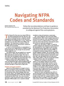
4.3 Class of Fire Symbols. See Figure 4.3(a) and Figure 4.3(b).
Copyright NFPA
Characteristics Square field Red background White symbol
Application For everyday use in workp public areas; supplementa can be used to increase comprehension
Square field Red background White symbol
For everyday use in workp public areas; supplementa can be used to increase comprehension
FIGURE 4.3(a) Recommended Marking System. [10: Figure B.2.1]
Copyright NFPA
FIGURE 4.3(b) LetterShaped Symbol Markings. [10: Figure B.2.2]
Chapter 5 Symbols for Use by the Fire Service 5.1 Introduction. 5.1.1* This chapter presents standard referents and symbols that shall be used for visually alerting fire fighters and other emergency responders during fire and related emergencies. 5.1.2* Fundamental shapes of symbols, as well as the background color and shape, are designated in this chapter. 5.1.3* Symbol Presentation. 5.1.3.1* Symbol Shapes. The shape of symbols shall be as illustrated in Section 5.2. 5.1.3.2 Symbol Background. 5.1.3.2.1 The symbol background shall be square. 5.1.3.2.2 The symbol background color shall be red, white, or blue as designated and shall Copyright NFPA
meet the requirements of ANSI Z535.1, Safety Color Code, for safety red, white, or blue. 5.1.3.3 Symbol Color. The symbol color shall be safety white or blue and shall meet the requirements of ANSI Z535.1, Safety Color Code, for safety white or blue. 5.1.3.4 Symbol Orientation. Symbol orientation shall not be altered from that shown in this chapter. 5.2* Symbols for Use by the Fire Service. See Table 5.2. Table 5.2 Symbols for Use by the Fire Service Symbol Fire Department Automatic Sprinkler Connection — Siamese
Characteristics Square field Red background White symbol
Application The identification and location of a f department automatic sprinkler conn
Fire Department Automatic Sprinkler Connection — Single
Square field Red background White symbol
The identification and location of a f department automatic sprinkler conn
Fire Department Standpipe Connection
Square field Red background White symbol
The identification and location of a f department standpipe connection
Fire Department Combined Automatic Sprinkler/ Standpipe Connection
Square field Red background White symbol
The identification and location of a f department combined automatic sprinkler/standpipe connection
Copyright NFPA
Table 5.2 Symbols for Use by the Fire Service Symbol Fire Hydrant (All Types)
Characteristics Square field Red background White symbol
Application The identification and location of a f hydrant
Automatic Sprinkler Control Valve
Square field Red background White symbol
The identification and location of an automatic sprinkler control valve
Electric Panel or Electric Shutoff
Square field Blue background White symbol
The identification and location of an electrical panel or other electric shu device
Gas Shutoff Valve
Square field Red background White symbol Red letter G
The location of a gas shutoff valve
FireFighting Hose or Standpipe Outlet
Square field Red background White symbol
The location of a firefighting hose o standpipe outlet
Fire Extinguisher
Square field Red background White symbol
The location of a fire extinguisher
Copyright NFPA
Table 5.2 Symbols for Use by the Fire Service Symbol Directional Arrow
Characteristics Square field Background green to correspond to accompanying sign White symbol
Application Direction to the location of firefight equipment or utility; always used in conjunction with, and adjacent to, symbol indicating the particular equi or utility Direction to the location of firefight equipment or utility; always used in conjunction with, and adjacent to, an symbol indicating the particular equi or utility The identification and location of chi care centers
Diagonal Directional Arrow
Square field Background green to correspond to accompanying sign White symbol
Child Care Center
Square field Blue infant and hands White background
Emergency Telephone
Red background White phone
The identification and location of fire service or emergency telephone syste
No Fire Fighting
Octagonal field White background Black truck Red prohibition symbol
To be posted on, near, or on the appr to buildings where fire fighting is no occur
SelfContained Breathing Apparatus (SCBA)
Square field White symbol Green background
To indicate the location of SCBA, breathing air connections, or refill lo
Chapter 6 Symbols for Use in Architectural and Engineering Drawings and Insurance Diagrams 6.1* Introduction. Copyright NFPA
6.1.1 This chapter presents symbols that shall be used in drawings and diagrams. 6.1.2* Symbol Presentation. 6.1.2.1* Symbol Shapes. The shape of symbols shall be as illustrated in Sections 6.2 through 6.12. 6.1.2.2 Screened Lines. Screened lines in the chapter shall not be considered part of the symbol, but shall be used to represent the piping, wiring, or mounting surface associated with the symbol. 6.1.2.3 Symbol Scale. All scales for symbols on any one drawing shall be the same relative size. 6.1.2.4* Symbol Orientation. Symbols shall be oriented to the walls, piping, electrical lines, and so forth to which they are attached. 6.2 Symbols for Site Features. 6.2.1 Buildings. 6.2.1.1 The exterior walls of buildings shall be outlined in single thickness lines if other than fire rated and double thickness lines if fire rated. 6.2.1.2* The perimeter of canopies, loading docks, and other openwalled structures shall be shown by broken lines. 6.2.2 Railroad Tracks. Railroad tracks shall be shown by a single line with cross dashes, as shown in Figure 6.2.2.
FIGURE 6.2.2 Symbol for Railroad Tracks. 6.2.3* Streets. Streets shall be shown. 6.2.4* Bodies of Water. Rivers, lakes, and so forth shall be outlined. 6.2.5 Fences. 6.2.5.1 Fences shall be shown by lines with x’s evenly spaced. 6.2.5.2* Gates shall be shown. 6.2.6 Property Lines. The notation given in Figure 6.2.6 shall indicate property lines.
FIGURE 6.2.6 Notation Indicating Property Lines. 6.2.7 Fire Department Access. The symbol for fire department access shall be as shown in Figure 6.2.7.
Copyright NFPA
FIGURE 6.2.7 Symbol for Fire Department Access. 6.2.8 Other Site Features. For other fire protection site features, see Section 6.4. 6.3 Symbols for Building Construction. 6.3.1* Types of Building Construction. Types of construction shall be shown narratively. 6.3.2* Height. Height shall be shown to indicate number of stories above ground, number of stories below ground, and height from grade to eaves. 6.3.3* Symbols for Walls and Parapets. See Table 6.3.3. Table 6.3.3 Symbols for Walls and Parapets Symbol
Description Wall — basic shape Smoke barrier wall ½hour firerated wall ½hour firerated/smoke barrier wall ¾hour firerated wall ¾hour firerated/smoke barrier wall 1hour firerated wall 1hour firerated/smoke barrier wall 2hour firerated wall 2hour firerated/smoke barrier wall 3hour firerated wall 3hour firerated/smoke barrier wall 4hour firerated wall 4hour firerated/smoke barrier wall Parapet — One cross for each 150 mm (6 in.) parapet that extends above roof (Shown is plan view of symbol.)
6.3.4 Symbols for Floor Openings, Wall Openings, Roof Openings, and Their Protection. See Table 6.3.4. Table 6.3.4 Symbols for Floor Openings, Wall Openings, Roof Openings, and Their Protection Symbol
Description Opening in wall Rated fire door in wall (less than 3 hours) Fire door in wall (3hour rated)
Copyright NFPA
Table 6.3.4 Symbols for Floor Openings, Wall Openings, Roof Openings, and Their Protection Symbol
Description Elevator in combustible shaft Elevator in noncombustible shaft Open hoistway Escalator Stairs in combustible shaft Stairs in firerated shaft Stairs in open shaft Skylight
6.3.5* Special Symbols for Cross Sections. The symbols shown in Table 6.3.5 shall be used to indicate features of cross sections. It is recognized that descriptive notes often are required. Table 6.3.5 Special Symbols for Cross Sections Symbol
Description Fireresistive floor or roof Wood joisted floor or roof Other floors or roofs Floor/ceiling or roof/ceiling assembly Floor on ground Truss roof
Comment
Note construction Details indicated, as necessary
Note construction
6.3.6 Miscellaneous Features. A number of features related to fire protection that do not fall under 6.3.1 through 6.3.5 are given in Table 6.3.6. Table 6.3.6 Miscellaneous Features Symbol
Description
Comment
Boiler Chimney Fire escape
Copyright NFPA
Describe height and construction
Table 6.3.6 Miscellaneous Features Symbol
Description Horizontal aboveground tank
Vertical aboveground tank
Belowground tank
Class I, Division 1 or 0
Comment Indicate type, dimensions, construction, capacity, pressurization, and content Indicate type, dimensions, construction, capacity, pressurization, and content Indicate type, dimensions, construction, capacity, pressurization, and content Hatch patterns for electrically classified locations
Class I, Division 1 or Zone 1
Hatch patterns for electrically classified locations
Class I, Division 2 or Zone 2
Hatch patterns for electrically classified locations
Designates the location of automated external defibrillators (AEDs) on plans
6.4* Water Supply and Distribution Symbols. See Table 6.4. Table 6.4 Water Supply and Distribution Symbols Symbol
Description Public water main Private water main Water main under building Suction pipe Thrust block
Riser Valves (general) Valve in pit Postindicator valve Keyoperated valve
Copyright NFPA
Table 6.4 Water Supply and Distribution Symbols Symbol
Description OS&Y valve (outside screw and yoke, rising stem) Indicating butterfly valve Nonindicating valve (nonrisingstem valve) Check valve Backflow preventer — double check type Backflow preventer — reduced pressure zone (RPZ) type Pressure regulating valve Pressure relief valve
Float valve Meter Private hydrant, one hose outlet
Public hydrant, two hose outlets
Public hydrant, two hose outlets, and pumper connection
Wall hydrant, two hose outlets
Private housed hydrant, two hose outlets
Siamese fire department connection Freestanding siamese fire department connection Single fire department connection Fire pump with drives Freestanding test header Wallmounted test header
Copyright NFPA
Table 6.4 Water Supply and Distribution Symbols Symbol
Description Screen/strainer
6.5 Symbols for Control Panels. See Table 6.5. Table 6.5 Symbols for Control Panels Symbol
Description Control panel — basic shape Fire alarm control panel Fire system annunciator alarm Annunciator panel — from NECA 100, symbol 7.006 Fire alarm transponder or transmitter Elevator status/recall Fire alarm communicator Fire system control panel Halon Carbon dioxide Dry chemical Foam Wet chemical Clean agent Water mist Deluge sprinkler Control panel for heating, ventilation, airconditioning, exhaust stairwell pressurization, or similar equipment Remote MIC for voice evacuation system Voice evacuation panel — from NECA 100, symbol 7.008 Fire alarm terminal cabinet — from NECA 100, symbol 7.009 Fire command system Fire alarm control unit Sprinkler alarm panel Relay alarm panel
Copyright NFPA
Table 6.5 Symbols for Control Panels Symbol
Description Data gathering panel Amplifier rack Purge panel Battery pack and charger — from NECA 100, symbol 7.010 Air sampling control detector panel with associated air sampling piping network — from NECA 100, symbol 7.011
6.6 Symbols Related to Means of Egress. See Table 6.6. Table 6.6 Symbols Related to Means of Egress Symbol
Description Comments Emergency light, batterypowered Number of lamps on unit to be indicated. Indicate whether light head(s) [lamp(s)] is remote from battery Illuminated exit sign, single face Indicate direction of flow for the face Illuminated exit sign, double face
Indicate direction of flow for each face
Combined batterypowered emergency light and illuminated exit sign
Number of lamps on unit to be indicated; indicate whether light head(s) [lamp(s)] is remote from battery; indicate direction of flow for the face Exit lighting fixture, arrows, and exit face as indicated on drawings (mounting heights to be determined by job specifications) — from NECA 100, symbol 2.005 From NECA 100, symbol 2.300
Exit lighting
Luminaire providing emergency illumination (filled in)
6.7* Symbols for Fire Alarms, Detection, and Related Equipment.
Copyright NFPA
Symbol
Description
Comments
6.7* Symbols for Fire Alarms, Detection, and Related Equipment. 6.7.1* Signal Initiating Devices and Activation Switches. See Table 6.7.1.
Table 6.7.1 Symbols for Signal Intiating Devices and Activation Sw Symbol
Description Manual station Manual station — Halon Manual station — carbon dioxide Manual station — dry chemical Manual station — foam Manual station — wet chemical Manual station — pull station/fire alarm box Manual station — clean agent Manual station — water mist Manual station — deluge sprinkler Fire alarm master box Drill key Preaction system Fire service or emergency telephone station Fire service or emergency telephone station — accessible Fire service or emergency telephone station — jack Fire service or emergency telephone station — handset Abort switch Abort switch — Halon Abort switch — carbon dioxide Abort switch — dry chemical
Copyright NFPA
Table 6.7.1 Symbols for Signal Intiating Devices and Activation Sw Symbol
Description Abort switch — clean agent Abort switch — water mist Abort switch — deluge sprinkler Abort switch — preaction system Abort switch — emergency power off Automatic detection and supervisory devices Heat detector (thermal detector) Heat detector — combination: rate of rise and fixed temperature Heat detector — rate compensation Heat detector — fixed temperature Heat detector — rate of rise only Heat detector — linetype detector (heatsensitive cable) Smoke/heat detector Smoke detector Smoke detector — photoelectric products of combustion detector Smoke detector — ionization products of combustion detector Smoke detector — beam transmitter Smoke detector — beam receiver Smoke detector — air sampling Smoke detector for duct Gas detector Flame detector
Copyright NFPA
Table 6.7.1 Symbols for Signal Intiating Devices and Activation Sw Symbol
Description Flame Ultraviolet Infrared Combination ultraviolet/infrared Visible radiation Flow detector/switch Pressure detector/switch Level detector/switch Tamper detector Valve with tamper detector/switch Output relay Temperature switch — high temperature Temperature switch — low temperature
6.7.2 Indicating Appliances. See Table 6.7.2. Table 6.7.2 Symbols for Indicating Appliances Symbol
Description Speaker/horn (electric horn) Minihorn Gong
Comments
Water motor alarm (water motor Shield optional gong) Bell — vibrating Bell — vibrating/strobe Bell — single stroke gong Bell — single stroke gong/ strobe
Copyright NFPA
Table 6.7.2 Symbols for Indicating Appliances Symbol
Description Bell — trouble
Comments
Bell — chime Horn with light as separate assembly Horn with light as one assembly Light (lamp, signal light, indicator lamp, strobe) Rotating beacon to indicate emergency response points Remote alarm indicating and test switch
6.7.3 Related Equipment. See Table 6.7.3. Table 6.7.3 Symbols for Related Equipment Symbol
Description Door holder Addressable input module Addressable output module
6.8* Symbols for Fire Extinguishing Systems. 6.8.1 Various Types of Fire Extinguishing Systems. 6.8.1.1 WaterBased Systems. See Table 6.8.1.1. Table 6.8.1.1 Symbols for WaterBased Systems Symbol
Description Wet charged system — automatically actuated Wet charged system — manually actuated Dry system — automatically actuated Dry system — manually actuated Foam system — automatically actuated Foam system — manually actuated Water mist extinguishing system — automatically actuated
Copyright NFPA
Table 6.8.1.1 Symbols for WaterBased Systems Symbol
Description Water mist extinguishing system — manually actuated
6.8.1.2 Dry Chemical Systems. See Table 6.8.1.2. Table 6.8.1.2 Symbols for Dry Chemical Systems Symbol
Description For liquid, gas, and electrical fires — automatically actuated For liquid, gas, and electrical fires — manually actuated For fires of all types (except metals) — automatically actuated For fires of all types (except metals) — manually actuated
6.8.1.3 Systems Utilizing a Gaseous Medium. See Table 6.8.1.3. Table 6.8.1.3 Symbols for Systems Utilizing a Gaseous Medium Symbol
Description Carbon dioxide system — automatically actuated Carbon dioxide system — manually actuated Halon system or clean agent extinguishing system — automatically actuated Halon system or clean agent extinguishing system — manually actuated
6.8.1.4 Supplementary Symbols. See Table 6.8.1.4. Table 6.8.1.4 Supplementary Symbols Symbol
Description Fully sprinklered space Partially sprinklered space Nonsprinklered space Water spray system
Copyright NFPA
6.8.2* Symbols for Fire Sprinklers. See Table 6.8.2. Table 6.8.2 Symbols for Fire Sprinklers Symbol
Description Upright sprinkler Pendent sprinkler Upright sprinkler; on sprig Upright sprinkler on top of riser nipple
Upright sprinkler on top of riser nipple with sprig
Pendent sprinkler; on drop nipple Sprinkler, with guard Sidewall sprinkler Outside sprinkler Open sprinkler on branch line Open sprinkler on branch line with sprig Water spray nozzle Window sprinklers
6.8.3* Symbols for Piping, Valves, Control Devices, and Hangers. See Table 6.8.3. Table 6.8.3 Symbols for Piping, Valves, Control Devices, and Hangers Symbol
Description Sprinkler piping and branch line Pipe trace heater Mechanical coupling Pipe hanger
Comments Indicate pipe size See NECA 100, symbol 5.106 This symbol is a diagonal stroke imposed on the pipe that it supports
Lateral brace Longitudinal brace
Copyright NFPA
Fourway brace
Only used to brace risers
Angle valve (angle hose valve)
Indicate size, type, and other required data
Table 6.8.3 Symbols for Piping, Valves, Control Devices, and Hangers Symbol
Description Check valve (general)
Comments
Alarm check valve
Specify size, direction of flow
Dry pipe valve
Specify size
Dry pipe valve with quick opening Specify size and type device (accelerator or exhauster) Deluge valve
Specify size and type
Preaction valve
Specify size and type
6.9 Symbols for Portable Fire Extinguishers. See Table 6.9. Table 6.9 Symbols for Portable Fire Extinguishers Symbol
Description Portable fire extinguisher
Comments Basic shape
Water extinguisher Foam extinguisher Dry chemical extinguisher — for liquid, gas, or electrical fires Dry chemical extinguisher — for fires of all types (except metals) CO 2 extinguisher
BC type ABC type
Halon or clean agent extinguisher Extinguisher for metal fires
6.10 Symbols for FireFighting Equipment. See Table 6.10. Table 6.10 Symbols for FireFighting Equipment Symbol
Copyright NFPA
Description Firefighting equipment CO 2 reel station
Comments Basic shape
Table 6.10 Symbols for FireFighting Equipment Symbol
Description Dry chemical reel station
Comments
Foam reel station Hose station, dry standpipe Hose station, wet standpipe Monitor nozzle, dry
Specify orifice size
Monitor nozzle, charged
Specify orifice size
6.11 Symbols for Smoke/Pressurization Control. See Table 6.11. Table 6.11 Symbols for Smoke/Pressurization Control Symbol
Description Purge controls — manual control
Comments
Hand (manual)/ offautomatic Fans — general
Arrow indicates direction of flow
Fans — duct
Arrow indicates direction of flow
Fans — roof Fans — wall
Arrow indicates direction of flow Arrow indicates direction of flow
Dampers — fire
Dampers — smoke
Dampers — fire/smoke
Dampers — motorized fire/smoke
Dampers — barometric Pressurized stairwell
Copyright NFPA
Orient as required for base or head injection
Table 6.11 Symbols for Smoke/Pressurization Control Symbol
Description Ventilation openings
Comments Orient as required for intake or exhaust
6.12* Miscellaneous Symbols. See Table 6.12. Table 6.12 Miscellaneous Symbols Symbol
Description Agent storage container Agent storage container — foam Agent storage container — Halon Agent storage container — carbon dioxide Agent storage container — clean agent Agent storage container — dry chemical Agent storage container — water mist Agent storage container — wet chemical Special spray nozzle Fusible link Fusible link with electrothermal feature Solenoid valve End of line device — resistor End of line device — relay End of line device — capacitor End of line device — diode Transfer switch — automatic with handle Transfer switch — manual with handle
Copyright NFPA
Chapter 7 Symbols for Use in PreIncident Planning Sketches 7.1 Introduction. 7.1.1* This chapter presents symbols that shall be used in preincident planning sketches. 7.1.2* Symbol Shapes. The symbol shapes were chosen for their ease of reproduction through either freehand drawing or with the use of templates. 7.2* Access Features, Assessment Features, Ventilation Features, and Utility Shutoffs. See Table 7.2. Table 7.2 Symbols for Access Features, Assessment Features, Ventilation Features, and Utility Shutoffs Symbol
Description Access features, assessment features, ventilation features, and utility shutoffs Access feature — fire department access point Access feature — fire department key box Access feature — roof access Assessment feature — fire alarm annunciator panel Assessment feature — fire alarm reset panel Assessment feature — fire alarm voice communication panel Assessment feature — smoke control and pressurization panel Assessment feature — sprinkler system water flow bell Ventilation feature — skylight Ventilation feature — smoke vent Utility shutoff — electric Utility shutoff — domestic water Utility shutoff — gas Specific variations — LPgas shutoff Specific variations — natural gas shutoff
Copyright NFPA
Comments Basic shape
Table 7.2 Symbols for Access Features, Assessment Features, Ventilation Features, and Utility Shutoffs Symbol
Description Specific variations — compressed natural gas shutoff
Comments
7.3 Detection/Extinguishing Equipment. See Table 7.3. Table 7.3 Symbols for Detection/Extinguishing Equipment Symbol
Description Detection/ extinguishing equipment Duct detector
Comments Basic shape
Heat detector Smoke detector Flow switch (water) Manual station — pull station/fire alarm box Tamper switch Halon system Dry chemical system Carbon dioxide system Wet chemical system Foam system Clean agent system Beam smoke detector
7.4 Water Flow Control Valves and Water Sources. See Table 7.4. Table 7.4 Symbols for Water Flow Control Valves and Water Sources Copyright NFPA
See Table 7.4. Table 7.4 Symbols for Water Flow Control Valves and Water Sources Symbol
Description Water flow control valves and water sources Postindicator valve
Comments Basic shape
Riser valve Sprinkler zone valve Sectional control valve Hose cabinet or connection Wall hydrant Test header (fire pump) Inspector’s test connection Fire hydrant Fire department connection Drafting site Water tank
7.5 Equipment Rooms. See Table 7.5. Table 7.5 Symbols for Equipment Rooms Symbol
Description Equipment rooms
Comments Basic shape
Airconditioning equipment room
AHUs = air handling units
Elevator equipment room Emergency generator room Fire pump room Telephone equipment room Boiler room Electrical/ transformer room
Copyright NFPA
7.6* Identification of Hazardous Materials. NFPA 704, Standard System for the Identification of the Hazards of Materials for Emergency Response, shall be permitted to be used to identify the location of hazardous materials within a structure.
Chapter 8 Symbology for Emergency Management Mapping 8.1 Use Table 8.1 to crossreference the damage operational symbols with their definitions. Table 8.1 Damage Operational Symbology Reference Symbol Types and Terms Incident (No levels) (violet)
Symbols
Definitions Not applicable
Natural Event (No levels) (black)
Not applicable
Operation (Level 1) (green)
Fully operational/open
Operation (Level 2) (blue)
Operational, but filled to capacity or otherwise closed
Operation (Level 3) (orange)
Operational, but partially damaged or partially incapacitated
Operation (Level 4) (red)
Destroyed or totally incapacitated
Infrastructure (Level 1) (green) Infrastructure (Level 2) (blue)
Fully operational/open
Copyright NFPA
Operational, but filled to capacity or otherwise closed
Table 8.1 Damage Operational Symbology Reference Symbol Types and Terms Infrastructure (Level 3) (orange)
Symbols
Infrastructure (Level 4) (red)
Definitions Operational, but partially damaged or partially incapacitated Destroyed or totally incapacitated
8.2 Operations Symbology. 8.2.1 Organizations, services, capabilities, or resources available during or implemented due to an emergency management situation. 8.2.2 Use Table 8.2.2 to crossreference the operations symbols with their definitions. Table 8.2.2 Operations Symbology Reference Symbol Types and Terms Operations Background Symbol (Background) Operations Frame Symbol (Frame) Emergency Medical Operation (Theme)
EMT Station Locations (Emergency Medical Feature) Medical Evacuation Helicopter Station (Emergency Medical Feature) Health Department Facility (Emergency Medical Feature)
Hospital (Emergency Medical Feature) Hospital Ship (Emergency Medical Feature) Medical Facilities Outpatient (Emergency Medical Feature)
Copyright NFPA
Symbols
Keystroke
Table 8.2.2 Operations Symbology Reference Symbol Types and Terms Morgue (Emergency Medical Feature)
Pharmacies (Emergency Medical Feature) Triage (Emergency Medical Feature)
Emergency Operation (Theme)
Emergency Collection/Evacuation Point (Emergency Operation Feature) Emergency Incident Command Center (Emergency Operation Feature) Emergency Operations Center (Emergency Operation Feature)
Emergency Public Information Center (Emergency Operation Feature) Emergency Public Service Center (Emergency Operation Feature) Emergency Shelters (Emergency Operation Feature) Emergency Staging Areas (Emergency Operation Feature) Emergency Teams (Emergency Operation Feature) Emergency Water Distribution Center (Emergency Operation Feature) Emergency Food Distribution Centers (Emergency Operation Feature)
Copyright NFPA
Symbols
Keystroke
Table 8.2.2 Operations Symbology Reference Symbol Types and Terms Fire Suppression Operation (Theme)
Fire Hydrant (Fire Suppression Feature)
Other Water Supply Location (Fire Suppression Feature) Fire Station (Fire Suppression Feature) Law Enforcement Operation (Theme) ATF (Law Enforcement Feature)
Border Patrol (Law Enforcement Feature) Customs Service (Law Enforcement Feature) DEA (Law Enforcement Feature)
DOJ (Law Enforcement Feature)
FBI (Law Enforcement Feature)
Police (Law Enforcement Feature)
Prison (Law Enforcement Feature)
Secret Service (Law Enforcement Feature) TSA (Law Enforcement Feature)
U.S. Coast Guard (Law Enforcement Feature)
Copyright NFPA
Symbols
Keystroke
Table 8.2.2 Operations Symbology Reference Symbol Types and Terms U.S. Marshals Service (Law Enforcement Feature)
Symbols
Keystroke
Sensor Operation (Theme)
Biological Sensor (Sensor Operation Feature)
Chemical Sensor (Sensor Operation Feature) Intrusion Sensor (Sensor Operation Feature)
Nuclear Sensor (Sensor Operation Feature)
Radiological Sensor (Sensor Operation Feature)
Notes: 1. Source: www.dictionary.com; combined definition of emergency and medical 2. Source: Based on the APHA public health mission statement 3. Source: MerriamWebster Online Dictionary 4. Source: Adapted from San Diego State University Emergency Plan Glossary, http://bfa.sdsu.edu/emergencyplan/glossary. 5. Source: Commonwealth of Virginia ICS, www.vdfp.state.va.us/components.htm 6. Source: EMS web site 7. Source: Adapted from www.firewise.org glossary of terms 8. Source: Adapted from MerriamWebster Online Dictionary definition of hydrant 9. Source: www.dictionary.com 10. Source: Adapted from MerriamWebster Online Dictionary, definition of sensor 11. Source: Adapted from MerriamWebster Online Dictionary definition of sensor and inherent knowledge of the process, d
8.3 Incidents Symbology. 8.3.1 Table 8.3.2 lists 8 themes and 42 features that symbolize a “cause of action” or “source of disaster.” 8.3.2 Use Table 8.3.2 to crossreference the Incidents symbols with their definitions. Table 8.3.2 Incidents Symbology Reference Copyright NFPA
8.3.2 Use Table 8.3.2 to crossreference the Incidents symbols with their definitions. Table 8.3.2 Incidents Symbology Reference Symbol Types and Terms Incidents Stage 01 Background Symbol (Background)
Keystroke !
The backgrou
Incidents Stage 01 Frame Symbol (Frame)
#
The frame sha
Civil Disturbance Incident (Theme)
A
Civil Demonstrations (Civil Disturbance Feature)
B
Human activi requiring vary attention A public displ
Civil Displaced Population (Civil Disturbance Feature)
C
Civil Rioting (Civil Disturbance Feature)
D
Criminal Activity Incident (Theme)
E
Bomb Threat (Criminal Activity Feature)
F
A warning of expression of
Bomb (Criminal Activity Feature)
G
An explosive conditions
Bomb Explosion (Criminal Activity Feature)
H
Looting (Criminal Activity Feature)
I
A violent outb nuclear explo integrity Burglary com emergency
Poisoning (Criminal Activity Feature)
J
Copyright NFPA
Symbols
Persons or gro to flee or to le in particular a armed conflic humanmade A public distu by one or mor persons, whic danger of, or of any other p (2) a threat or violence by on three or more ability of imm the performan would constitu in, damage or the person of An unlawful p participates
Use of a poiso
Table 8.3.2 Incidents Symbology Reference Symbol Types and Terms Shooting (Criminal Activity Feature)
Symbols
Keystroke K
Use of a firea
Fire Incident (Theme)
L
Commercial Facility Fire (Fire Incident Feature)
M
Forest Fire (Fire Incident Feature)
N
Grassland Fire (Fire Incident Feature)
O
An uncontroll grasses, grass
Hot Spot (Fire Incident Feature)
P
An area of int particularly ac
Industrial Facility Fire (Fire Incident Feature)
Q
Origin (Fire Incident Feature)
R
A fire that ori resulting in pa and/or bod Location of w
Residential Fire (Fire Incident Feature)
S
School Fire (Fire Incident Feature)
T
Smoke (Fire Incident Feature)
U
Special Needs Fire (Fire Incident Feature)
V
Hazardous Incident (Theme)
W
Chemical Agent (Hazardous Incident Feature)
X
Corrosive Material (Hazardous Incident Feature)
Y
Copyright NFPA
The destructiv or technologic human neglig A fire that ori resulting in pa and/or bodily An uncontroll
A fire affectin partial or tota smoke inhalat A fire that ori resulting in pa bodily injury, The visible pr
A fire that aff homes or assi destruction of inhalation, or See Note 11.
A chemical su operations to serious injury Uncontrolled solid that caus the site of con
Table 8.3.2 Incidents Symbology Reference Symbol Types and Terms Dangerous When Wet (Hazardous Incident Feature)
Symbols
Keystroke Z
Explosive (Hazardous Incident Feature)
a
Flammable Gas (Hazardous Incident Feature)
b
Flammable Liquid (Hazardous Incident Feature)
c
Flammable Solid (Hazardous Incident Feature)
d
NonFlammable Gas (Hazardous Incident Feature)
e
Organic Peroxides (Hazardous Incident Feature)
f
Oxidizers (Hazardous Incident Feature)
g
Radioactive Material (Hazardous Incident Feature)
h
Spontaneously Combustible (Hazardous Incident Feature)
i
Toxic Gas (Hazardous Incident Feature)
j
Copyright NFPA
Uncontrolled that, by conta flammable or greater than 1 Uncontrolled substance or a function by ex and heat) or th function in a s by explosion Uncontrolled material that i (14.7 psia) of 20°C (68°F) o at 101.3 kPa ( less by volum kPa (14.7 psia lower limit Uncontrolled having a flash
Uncontrolled desensitized e 1, which are w plasticizer to Uncontrolled material (or m pressure of 28 is not classifie No definition
Unc that can, gene combustion of Uncontrolled material havin
Uncontrolled solid that, eve ignition sou in contact wit and without a Uncontrolled presents a haz
Table 8.3.2 Incidents Symbology Reference Symbol Types and Terms Toxic and Infectious (Hazardous Incident Feature)
Symbols
Keystroke k
Uncontrolled substance that of a living org easily be trans Uncontrolled unexploded w
Unexploded Ordnance (Hazardous Incident Feature)
l
Air Incident (Theme)
m
An event death, or the d
Air Accident (Air Incident Feature)
n
Air Hijacking (Air Incident Feature)
o
Marine Incident (Theme)
p
A sudden, une fuselage dama transportation procedures or The unexpect aboard an airc resulting in pa and/or the red An event invo bodily injury,
Marine Accident (Marine Incident Feature)
q
Marine Hijacking (Marine Incident Feature)
r
Rail Incident (Theme)
s
Rail Accident (Rail Incident Feature)
t
Rail Hijacking (Rail Incident Feature)
u
Vehicle Incident (Theme)
v
Vehicle Accident (Vehicle Incident Feature)
w
Vehicle Hijacking (Vehicle Incident Feature)
x
Copyright NFPA
A sudden, une resulting in ve and/or the dis The unexpect aboard a boat resulting in pa and/or the red An event invo injury, death,
A sudden, une vehicl and/or the dis The unexpect aboard a whee of individuals injury or death An event invo in damage, bo transportation A sudden, une in damage, bo transportation The unexpect aboard a vehic resulting in pa and/or the red
Table 8.3.2 Incidents Symbology Reference
Symbol Types and Terms Symbols Keystroke Notes: 1. Source: MerriamWebster Online Dictionary 2. Source: United Nations Guiding Principles on Internal Displacement 3. Source: 18 USC Section 2102 4. Source: www.dictionary.com; combined definitions of criminal and activity 5. Source: International military definition 6. Source: http://peaceofficers.com glossary 7. Source: www.realdictionary.com 8. Source: Adapted from forest fire definition and the Forestry Resource glossary located at http://forestry.about.com/library 9. Source: U.S. Department of Agriculture, Forest Service, www.fs.fed.us 10. Source: www.firewise.org 11. Note: All of these proposed definitions are from the following source: Office of Hazardous Materials Safety, Hazmat Reg 12. Source: Adapted from NATO definition, www.nato.int/docu/stanag/aap006/aap6.htm 13. Source: www.dictionary.com, definition of hijack
8.4 Natural Events Symbology. 8.4.1 A natural event is a phenomenon found in or created by naturally occurring conditions. 8.4.2 Use Table 8.4.2 to crossreference the Natural Events symbols with their definitions. Table 8.4.2 Natural Events Symbology Reference Symbol Types and Terms Natural Events Stage 01 Background Symbol (Background)
Symbols
#
Natural Events Stage 01 Frame Symbol (Frame) Geologic (Theme) Aftershock (Geologic Feature)
Keystroke !
Reserved A
Avalanche (Geologic Feature)
B
Earthquake Epicenter (Geologic Feature)
C
Landslide (Geologic Feature)
D
Subsidence (Geologic Feature)
E
Copyright NFPA
Table 8.4.2 Natural Events Symbology Reference Symbol Types and Terms Volcanic Eruption (Geologic Feature)
Symbols
G
Volcanic Threat (Geologic Feature)
HydroMeteorologic (Theme) Drizzle (HydroMeteorologic Feature)
Keystroke F
Reserved H
Drought (HydroMeteorologic Feature)
I
Flood (HydroMeteorologic Feature)
J
Fog (HydroMeteorologic Feature)
K
Hail (HydroMeteorologic Feature)
L
Inversion (HydroMeteorologic Feature)
M
Rain (HydroMeteorologic Feature)
N
Sand Dust Storm (HydroMeteorologic Feature)
O
Snow (HydroMeteorologic Feature)
P
Copyright NFPA
Table 8.4.2 Natural Events Symbology Reference Symbol Types and Terms Thunderstorm (HydroMeteorologic Feature)
Symbols
Keystroke Q
Tornado (HydroMeteorologic Feature)
R
Tropical Cyclone (HydroMeteorologic Feature)
S
Tsunami (HydroMeteorologic Feature)
T
Infestation (Theme) Insect Infestation (Infestation Feature)
Reserved U
Microbial Infestation (Infestation Feature)
V
Reptile Infestation (Infestation Feature)
W
Rodent Infestation (Infestation Feature)
X
Notes: 1. Source: Dictionary of Geological Terms, Third Ed. 2. Source: logical extension of volcanic eruption 3. Source: Adapted from National Weather Service glossary, www.nws.noaa.gov/glossary.htm
8.5 Infrastructures Symbology. 8.5.1 Infrastructure is the basic facilities, services, and installations needed for the functioning of a community or society, such as transportation and communications systems, water and power lines, and public institutions, including schools, post offices, and prisons. 8.5.2 Use Table 8.5.2 to crossreference the Infrastructures symbols with their definitions. Table 8.5.2 Infrastructure Symbology Reference Symbol Types and Terms
Copyright NFPA
Symbols
Keystroke
Table 8.5.2 Infrastructure Symbology Reference Symbol Types and Terms Infrastructures Background Symbol (Background) Infrastructures Frame Symbol (Frame) Agriculture and Food Infrastructure (Theme) Agricultural Laboratory (Agriculture and Food Feature) Animal Feedlot (Agriculture and Food Feature) Commercial Food Distribution Center (Agriculture and Food Feature) Farm/Ranch (Agriculture and Food Feature) Food Production Center (Agriculture and Food Feature) Food Retail (Agriculture and Food Feature) Grain Storage (Agriculture and Food Feature) Banking, Finance, and Insurance Infrastructure (Theme) ATM (Banking, Finance, and Insurance Feature) Bank (Banking, Finance, and Insurance Feature) Bullion Storage (Banking, Finance, and Insurance Feature) Federal Reserve Bank (Banking, Finance, and Insurance Feature) Financial Exchange (Banking, Finance, and Insurance Feature) Financial Service Other (Banking, Finance, and Insurance Feature)
Commercial Infrastructure (Theme) Chemical Plant (Commercial Infrastructure Feature) Firearm Manufacturer (Commercial Infrastructure Feature)
Copyright NFPA
Symbols
Keystroke
Table 8.5.2 Infrastructure Symbology Reference Symbol Types and Terms Firearm Retailer (Commercial Infrastructure Feature) Hazardous Material Production (Commercial Infrastructure Feature) Hazardous Material Storage (Commercial Infrastructure Feature)
Industrial Site (Commercial Infrastructure Feature) Landfill (Commercial Infrastructure Feature)
Pharmaceutical Manufacturer (Commercial Infrastructure Feature) Superfund Site National Priorities List (Commercial Infrastructure Feature)
Toxic Release Inventory (Commercial Infrastructure Feature) Educational Facilities Infrastructure (Theme) College/University (Educational Facilities Feature) School (Educational Facilities Feature) Energy Facilities Infrastructure (Theme) Generation Station (Energy Facilities Feature) Natural Gas Facility (Energy Facilities Feature) Nuclear Facility (Energy Facilities Feature) Petroleum Facility (Energy Facilities Feature)
Copyright NFPA
Symbols
Keystroke
Table 8.5.2 Infrastructure Symbology Reference Symbol Types and Terms Propane Facility (Energy Facilities Feature) Government Site Infrastructure (Theme) Military Infrastructure (Theme)
Military Armory (Military Feature)
Military Base (Military Feature)
Postal Service Infrastructure (Theme) Postal Distribution Center (Postal Feature) Post Office (Postal Feature) Public Venue Infrastructure (Theme) Church (Public Venues Feature) Enclosed Facility (Public Venues Feature) Mosque (Public Venues Feature) Open Facility (Public Venues Feature) Recreational Area (Public Venues Feature) Religious Institution (Public Venues Feature) Synagogue (Public Venues Feature) Temple (Public Venues Feature) Special Needs Infrastructure (Theme)
Copyright NFPA
Symbols
Keystroke
Table 8.5.2 Infrastructure Symbology Reference Symbol Types and Terms Adult Day Care (Special Needs Feature)
Child Day Care (Special Needs Feature) Elder Care (Special Needs Feature)
Telecommunications Infrastructure (Theme) Telecommunications Facility (Telecommunications Feature) Telecommunications Tower (Telecommunications Feature) Transportation Infrastructure (Theme)
Air Traffic Control Facility (Transportation Feature) Airport (Transportation Feature)
Bridge (Transportation Feature)
Bus Station (Transportation Feature) Ferry Terminal (Transportation Feature) Helicopter Landing Site (Transportation Feature) Lock (Transportation Feature)
Maintenance Facility (Transportation Feature) Port (Transportation Feature) Rail Station (Transportation Feature)
Copyright NFPA
Symbols
Keystroke
Table 8.5.2 Infrastructure Symbology Reference Symbol Types and Terms Rest Stop (Transportation Feature)
Ship Anchorage (Transportation Feature) Toll Facility (Transportation Feature)
Traffic Control Point (Transportation Feature) Traffic Inspection Facility (Transportation Feature)
Tunnel (Transportation Feature)
Water Supply Infrastructure (Theme)
Critical Valve (Water Supply Feature) Dam (Water Supply Feature) Discharge Outfall (Water Supply Feature)
Ground Well (Water Supply Feature)
Pumping Station (Water Supply Feature) Reservoir (Water Supply Feature) Storage Tower (Water Supply Feature) Surface Water Intake (Water Supply Feature) Water Treatment Facility (Water Supply Feature)
Copyright NFPA
Symbols
Keystroke
Table 8.5.2 Infrastructure Symbology Reference
Symbol Types and Terms Symbols Keystroke Notes: 1. Source: Adapted from www.dictionary.com 2. Source: Adapted from www.hyperdictionary.com 3. Source: www.hyperdictionary.com; combined definitions of bullion and storage 4. Source: Yahoo! Finance glossary, http://biz.yahoo.com/f/g 5. Source: Webster’s New World Dictionary; combined definitions of firearm and manufacture 6. Source: Webster’s New World Dictionary; combined definitions of firearm and retail 7. Source: San Diego State University Emergency Plan Glossary, http://bfa.sdsu.edu/emergencyplan/glossary.htm 8. Source: The Federal Aviation Administration glossary, www.faa.gov/library/glossaries 9. Source: Webster’s New World Dictionary; combined definitions of pharmaceutical and manufacture 10. Source: Environmental Protection Agency, www.epa.gov 11. Source: www.hyperdictionary.com; combined definitions of educational and facility 12. Source: Adapted from MerriamWebster Online Dictionary definitions of college and university 13. Source: Adapted from MerriamWebster Online Dictionary 14. Source: www.hyperdictionary.com; combined definitions of generation and station 15. Source: Adapted from Webster’s New World Dictionary 16. Source: J. Reimer Training and Doctrine Digital Library, military terms glossary, www.adtdl.army.mil/cgibin/atdl.dll/fm 17. Source: www.hyperdictionary.com, adapted definition of depot 18. Source: Nextlinx, www.nextlinx.com/global%5Fcontent/traderefs/glossary.shtml, definition of weigh station 19. Source: County of Maui (Hawaii) Water Supply glossary, www.mauiwater.org/glossary.html, combined definitions of 20. Source: “Valve World” glossary, www.valveworld.net/glossary/index.asp, definition of control valve 21. Source: Combined definitions of outfall from the Ohio Environmental Protection Agency glossary and discharge www.epa.state.oh.us/ddagw/documents/swapdocglo.pdf and http://ga.water.usgs.gov/edu/dictionary.html 22. Source: Adapted from the U.S. Geological Survey Water Science glossary, http://ga.water.usgs.gov/edu/dictionary.html 23. Source: Ridenbaugh Press, www.ridenbaugh.com 24. Source: Ohio Environmental Protection Agency glossary (term upground reservoir), http://www.epa.state.oh.us/ddagw/d 25. Source: U.S. Geological Survey Water Resources of New Hampshire and Vermont glossary. Combined definitions of http://nh.water.usgs.gov/Publications/OFR01328/ofr01328_glossary.pdf
Annex A Explanatory Material Annex A is not a part of the requirements of this NFPA document but is included for informational purposes only. This annex contains explanatory material, numbered to correspond with the applicable text paragraphs. A.3.2.1 Approved. The National Fire Protection Association does not approve, inspect, or certify any installations, procedures, equipment, or materials; nor does it approve or evaluate testing laboratories. In determining the acceptability of installations, procedures, equipment, or materials, the authority having jurisdiction may base acceptance on compliance with NFPA or other appropriate standards. In the absence of such standards, said authority may require evidence of proper installation, procedure, or use. The authority having jurisdiction may also refer to the listings or labeling practices of an organization that is concerned with product evaluations and is thus in a position to determine compliance with appropriate standards for the current production of listed items. Copyright NFPA
A.3.2.2 Authority Having Jurisdiction (AHJ). The phrase “authority having jurisdiction,” or its acronym AHJ, is used in NFPA documents in a broad manner, since jurisdictions and approval agencies vary, as do their responsibilities. Where public safety is primary, the authority having jurisdiction may be a federal, state, local, or other regional department or individual such as a fire chief; fire marshal; chief of a fire prevention bureau, labor department, or health department; building official; electrical inspector; or others having statutory authority. For insurance purposes, an insurance inspection department, rating bureau, or other insurance company representative may be the authority having jurisdiction. In many circumstances, the property owner or his or her designated agent assumes the role of the authority having jurisdiction; at government installations, the commanding officer or departmental official may be the authority having jurisdiction. A.3.2.4 Listed. The means for identifying listed equipment may vary for each organization concerned with product evaluation; some organizations do not recognize equipment as listed unless it is also labeled. The authority having jurisdiction should utilize the system employed by the listing organization to identify a listed product. A.3.3.2 Referent. A referent can be abstract, such as a condition concept, function, relationship, fact, or action. A.3.3.4 Supplementary Indicators. Effectiveness of symbols can be supplemented by figures, numbers, subscripts, or letter abbreviations. These supplementary indicators can be placed inside of, or adjacent to, the symbol as seen fit. A legend of these indicators, with their meaning, should accompany each set of documents on which they are used. A.3.3.5 Symbol. Ideally, a symbol should be graphically simple, should be readily understood, should have a strong impact, and should be easily remembered. A.4.1.2.3 Changes in line thickness, scale, or details are not recommended. In practice, symbols can be combined with other symbols or devices such as words and lighted panels to provide optimal visual alerting. A.4.1.2.4 The user is referred to other standards, such as those prepared by the NFPA Committee on Safety to Life and the ANSI Z535 Committee on Safety Signs and Colors, for such information. A.4.1.3 Reflective material or selfluminous materials can be used. Consideration needs to be given to the proper mounting of selfluminous symbols in welllighted locations to ensure charging by exposure to ambient light. A.4.1.3.2.1 See Figure A.4.1.3.2.1.
Copyright NFPA
FIGURE A.4.1.3.2.1 Example of a Prohibition Symbol. A.4.1.3.4 Examples of combinations of symbols that can be used include Exit Symbol Arrow, Exit Symbol with International Symbol of Accessibility, and Exit Symbol with Arrow and International Symbol of Accessibility. A.4.2 Use of the symbols is not restricted to the examples cited. A.5.1.1 The purpose of this chapter is to present uniform firefighting symbols in order to improve communication wherever symbology is employed in order to provide information to fire fighters and other emergency responders. This chapter provides uniformity in the selection of symbols that are intended to assist fire fighters in locating utilities and firefighting equipment. A.5.1.2 In practice, symbols can be combined with other devices, such as words and lighted panels, to provide optimal visual alerting. This chapter does not specify viewing distance, size, or optimal combinations of symbols, words, and other presentations. A.5.1.3 Reflective material or selfluminous materials can be used. Consideration needs to be given to the proper mounting of selfluminous symbols in welllighted locations to ensure charging by exposure to ambient light. A.5.1.3.1 Drawing scale, line thickness, and so forth are the subject of standards on drawing practice. A.5.2 Use of the symbols is not restricted to the examples cited. The symbol for fire hydrant (all types) shown in Table 5.2 can be of particular use where vehicles or snowfall frequently obscures hydrant locations. A.6.1 This chapter on architectural and engineering symbols draws heavily on the symbols already developed by various societies, agencies, and industry. The purpose of this chapter is to provide uniformity in the use of fire safety and related Copyright NFPA
symbols in the preparation of drawings and diagrams. The symbols in this chapter are intended to be simple, transferable by use of templates, and limited to those referents that are used repetitively in a set of drawings. The symbols in this chapter are intended for, but not limited to, architectural and engineering drawings, fire detection and suppression drawings, and fire risk and/or loss analysis diagrams. The effectiveness of the symbols in this chapter can be enhanced by the use of supplementary figures, subscripts, numbers, or letter abbreviations. Devices infrequently used in a given set of drawings and diagrams are not standardized by this document. They usually are accompanied by narrative description, either on the drawing or in specifications. A.6.1.2 Diagram Preparation and Contents. Where appropriate, diagrams include, but are not limited to, the following (see Figure A.6.1.2): (1)
Title block indicating the following: (a) Name of company or organization (b) Person making drawing and date of drawing (c) Name and location of facility involved
(2)
“North” direction arrow properly oriented to the position of buildings shown.
(3)
Scale of diagram, if used, or “not to scale.” Scale can be given with a bar measurement if reduction copies are to be made.
FIGURE A.6.1.2 Diagram to Exemplify the Use of Symbols for Risk Analysis Drawing. Copyright NFPA
A.6.1.2.1 Drawing scale, line thickness, and so forth are the subject of standards on drawing practice. A.6.1.2.4 See Figure A.6.1.2.4(a) and Figure A.6.1.2.4(b) for examples of symbol orientation.
FIGURE A.6.1.2.4(a) Symbol Orientation — Example 1.
FIGURE A.6.1.2.4(b) Symbol Orientation — Example 2. A.6.2.1.2 See Figure A.6.2.1.2 for examples of openwalled structures.
FIGURE A.6.2.1.2 Examples of OpenWalled Structures. A.6.2.3 See Figure A.6.2.3 for an example of a street.
FIGURE A.6.2.3 Example of a Street. A.6.2.4 See Figure A.6.2.4 for examples of bodies of water.
Copyright NFPA
FIGURE A.6.2.4 Examples of Bodies of Water. A.6.2.5.2 See Figure A.6.2.5.2 for an example of a fence with a gate.
FIGURE A.6.2.5.2 Example of a Fence with a Gate. A.6.3.1 See Figure A.6.3.1 for an example of building construction identification. (See NFPA 220, Standard on Types of Building Construction.)
FIGURE A.6.3.1 Example of Building Construction Identification. A.6.3.2 See Figure A.6.3.2 for an example of height symbols used for a building.
FIGURE A.6.3.2 Examples of Building Height Symbols. (Figure includes copyrighted material of Insurance Services Office with its permission. Copyright, Insurance Services Office, 1975.) A.6.3.3 See Figure A.6.3.3(a) and Figure A.6.3.3(b) for examples of wall symbols. See Figure A.6.3.3(a) for examples of parapet symbols used for a building.
Copyright NFPA
FIGURE A.6.3.3(a) Symbols Used to Note Wall Ratings and Parapets on Life Safety Plans and Risk Analysis Plans/Cross Sections.
FIGURE A.6.3.3(b) Symbol Used to Note Wall Ratings on Design and Construction Documents. A.6.3.5 See Figure A.6.3.5 for an example of crosssection symbols used for a building.
Copyright NFPA
FIGURE A.6.3.5 Examples of Symbols and Notations Used for Fire Risk Analysis Cross Section. (Figure includes copyrighted material of Insurance Services Office with its permission. Copyright, Insurance Services Office, 1975.) A.6.4 For private hydrant, one hose outlet; public hydrant, two hose outlets; public hydrant, two hose outlets and pumper connection; wall hydrant, two hose outlets; and private housed hydrant, two hose outlets, all shown in Table 6.4, symbol elements can be utilized in any combination to fit the type of hydrant. A.6.7 Additional subscript identifiers can be included with a slash after the primary subscript to indicate such things as WP for weather proof or EP for explosion proof or others. A.6.7.1 For the manual station symbol shown in Table 6.7.1, electrical or mechanical actuation can be shown. See NFPA 2001, Standard on Clean Agent Fire Extinguishing Systems, for a generic list of Copyright NFPA
clean agents. The telephones referred to in the fire service or emergency telephone station symbols, shown in Table 6.7.1, are those for a dedicated system for fire and related emergencies. Temperature rating of heat detectors, in Table 6.7.1, can be shown. Velocity can be shown for the smoke detector for duct symbol shown in Table 6.7.1. For the gas detector symbol shown in Table 6.7.1, the drawing should show the type of gas or gases being monitored. The drawing should indicate the lower explosive limit (LEL) and/or the upper explosive limit (UEL) of gas or gases. A.6.8 These symbols are intended for use in identifying the type of system installed to protect an area within a building. A.6.8.2 For sprinklers shown in Table 6.8.2, the temperature rating of the sprinkler and other characteristics can be shown via legends where a limited number of an individual type of sprinkler is called for by the design. A.6.8.3 See also Table 6.4 for related symbols. A.6.12 The electrothermal link (ETL) is a multipurpose dualresponse fusible link/release device. These devices are used in various applications, such as smoke/damper control and door closures. The symbol should be shown with its rated thermal point. A.7.1.1 The purpose of this chapter is to provide uniformity in the use of fire safety and related symbols in the preparation of preincident planning sketches. The symbols in this chapter are provided to assist fire service or emergency response personnel who are responsible for preparing and using preincident planning sketches. A.7.1.2 Triangle symbols are used for access features, assessment features, ventilation features, and utility shutoffs and can point at a specific location or direction. Diamond symbols identify a specific location by touching a wall. Circle symbols are used for all piping system components, such as valves, since most pipes are round. Square symbols are used for room designations, as they represent most rooms having four sides. A.7.2 For Section 7.2 through Section 7.5, other features to complete the preincident planning sketch can be used as appropriate. A.7.6 Figure A.7.6 shows an example of hazardous identification.
FIGURE A.7.6 Example of Hazardous Identification.
Annex B Additional Explanatory Information on Chapters 1 Copyright NFPA
through 6 This annex is not a part of the requirements of this NFPA document but is included for informational purposes only. B.1 Reserved. B.2 Reserved. B.3 Additional Explanatory Information on Chapter 4. B.3.1 Symbol Testing. Two or more versions of a symbol were developed for the referents listed in Chapter 4. The effectiveness of each of these symbols was evaluated by testing its meaningfulness (i.e., understandability) with groups of different participants. On the basis of these results, a symbol was selected for each referent. In some cases, the symbols were refined graphically to incorporate modifications suggested by the test results. Symbol development and refinement included the efforts of research psychologists, graphic designers, safety engineers, and fire professionals. The life safety symbols were tested in the course of several different research projects during a 7year period. These results are referenced in a series of publications by the National Bureau of Standards. Although a variety of testing procedures were used to assess understandability, the basic method consisted of asking people either to write down short definitions or to pick the correct definition from a set of carefully selected choices. In several studies, data on symbol preference and rated effectiveness also were obtained. For these testing efforts, one set of participants consisted of 222 industrial personnel and 78 students; another set consisted of 271 miners and mine personnel; and another set consisted of 94 paid volunteers. No major differences between participant groups were observed for the symbols selected for Chapter 4. In addition to the studies of understandability, a detailed assessment was made of exit symbol visibility. This study used a laboratory optical viewing system to present a set of exit symbols included in a much larger set (108) of safety and information symbols. Three viewing conditions that simulated smoke were used (luminance of 0.085, 0.060, and 0.032 candela/m 2 ). Fortytwo participants were familiarized with a randomly selected set of exit symbols to identify the separate effects of understandability and visibility. The symbol given in Chapter 4 was the symbol that was most frequently identified correctly under all three viewing conditions. In addition, the identification data were virtually the same whether participants had been familiarized with the symbol or not — suggesting that the symbol has high initial understandability. (This suggestion is reinforced by the high percentages of correct identification found in those studies that evaluated understandability.) The results of the visibility testing program are important because an exit symbol must be both well understood and visible when under degraded viewing conditions such as smoke. The goal of the overall testing program was to identify versions or elements of symbols for Copyright NFPA
the selected referents that appeared to be most effective in communicating the intended message. It is recognized that further education and/or supplemental word messages can be useful in optimizing the effectiveness of these symbols with the general public. Nevertheless, the symbols selected have demonstrated good initial understandability. Symbols for the referents generally showed good understandability (better than 85 percent correct identification). Symbols that presented some understandability problems included “No Exit” and “Fire Alarm Call Point.” The examples shown herein, however, represent the imagery that was best understood. It is hoped that use of these images will strengthen public recognition. It also should be noted that the symbol for handicapped accessibility was not tested in this program. It is, however, in an existing ANSI standard, A117.1, Specifications for Making Buildings and Facilities Accessible to and Usable by Physically Handicapped People, and has achieved wide use and good recognition. B.4 Additional Explanatory Information on Chapter 5. B.4.1 Symbol Testing. At least two versions of a symbol were developed for each of the following referents: (1)
Fire department automatic sprinkler connection — siamese
(2)
Fire department standpipe connection
(3)
Fire department combined automatic sprinkler/standpipe connection
(4)
Fire hydrant (all types)
(5)
Automatic sprinkler control valve
(6)
Electric panel or electric shutoff
The following referents are discussed in this section: (1)
Gas shutoff valve
(2)
Firefighting hose or standpipe outlet
(3)
Fire extinguisher
(4)
Directional arrow
(5)
Diagonal directional arrow
Subsequently, the effectiveness of the symbols was evaluated by testing their meaningfulness to groups of fire professionals; the procedures are outlined in this section. On the basis of the test results, a symbol was selected for each referent. This set of symbols was further refined graphically, incorporating modifications suggested by the test results. Symbol development and refinement through a Subcommittee on Visual Alerting Symbols included the efforts of fire professionals, graphic artists and designers, research psychologists, and safety engineers. Symbols for gas shutoff valve, firefighting hose or standpipe outlet, fire extinguisher, directional arrow, and diagonal directional arrow were adapted from International Organization for Standardization (ISO) publications. The fire extinguisher symbol was Copyright NFPA
included in the test procedure. Although the standpipe outlet symbol was not tested in isolation, it was incorporated as an element in two of the tested symbols (fire department standpipe connection and fire department combined automatic sprinkler/standpipe connection). Participants in the test program included fire professionals attending a national convention or local (Maryland) training classes and totaled 86 participants. The test procedure involved two phases. In the first phase, the participants were shown one symbol at a time, in slide form, and were asked to write down a short definition of what they thought each symbol meant. In the second phase, two symbolic versions of each referent were shown together, and their intended meaning was provided; the participants indicated which version (if either) of each pair they felt better conveyed the meaning. They also were asked to give the reason for their preference and were free to offer any suggestions for improvement. The goal of the testing program was to identify versions or elements of symbols for the selected referents that were most effective in visually alerting fire fighters. It is recognized that education might be required to optimize the effectiveness of the symbols for fire fighters. Nevertheless, it is important to select symbols that initially are meaningful. Symbols for seven of the nine referents tested showed good recognizability (85 to 100 percent) and no serious confusion with other possible meanings. However, for two referents — wall hydrant and gas control valve — recognition was poor, and confusion was common for both symbolic versions of each message. Therefore, no symbol for these two referents is presented in this standard. Graphic improvements and alternative conceptions are being sought. (A symbol for a gas shutoff valve was accepted for the 1991 edition of NFPA 170, Standard for Firesafety Symbols.) B.4.2 The NFPA Committee on Fire Safety Symbols was able to identify a set of shapes for symbols to be used to direct responding fire fighters. B.5 Additional Explanatory Information on Chapter 6. B.5.1 Symbol Selection Procedure. See Figure B.5.1 for an example of the procedures involved in selecting fire safety symbols.
Copyright NFPA
FIGURE B.5.1 Symbol Selection Procedure. B.5.2 Discussion of Basic Symbols. B.5.2.1 Symbol Testing. Inevitably, when a new standard is introduced to a field in which standardized symbols are not established and everyone is acting independently, controversy looms over the effort as to which (whose) alleged “standard” should be used. Such controversy can be met only with a national logic for meeting the standardization task. Such logic was used in developing former NFPA 172, Standard Fire Protection Symbols for Architectural and Engineering Drawings, now incorporated into Chapter 6. B.5.2.2 This symbology effort ultimately employed the following steps: Copyright NFPA
(1)
Identify problem. Is a standard for fire protection symbols needed?
(2)
Identify referents. What devices should be symbolized? Consider applicability to fire protection and frequency of use.
(3)
Identify symbols’ availability. What symbols exist, and how widely are they used for fire protection and other disciplines?
(4)
Develop a system of symbol selection. Can a system be identified so that referents and symbols can be rationally selected or developed? (See B.5.1.)
(5)
Can a scheme of basic shapes be utilized in developing symbol sets for categories of referents?
(6)
Adhere to the scheme. Make exceptions only where an overwhelming level of usage makes changes unreasonable.
(7)
Avoid conflicts. Are there other practices and/or standards with which the proposed standard might be in conflict?
B.5.2.3 To accomplish step B.5.2.2(5), two factors had to be considered. First, there is very little agreement on symbols throughout North America. For the most part, various industry segments disagree on symbols and even on basic shapes. Second, the ISO Committee on Fire Protection Symbols for Use on Drawings completed most of its work on this subject before 1980 and proposed a set of basic symbol shapes. B.5.2.4 With the two foregoing considerations, the NFPA Committee on Fire Safety Symbols was able to develop a set of basic shapes for symbols to be used on fire protection drawings. The basic shapes shown in Table B.5.2.4 were selected by uniting the ISO proposed basic shapes and, where existent, the North American common practice. Thus, the collection of shapes (menu) represents a compromise with the sole major objective of developing a symbols standard aimed at a common language to improve future communication among users of fire protection drawings worldwide. Table B.5.2.4 Basic Symbol Shapes and Relative Sizes General Referent Major Elements Automatically actuating systems Manually actuating systems Control panel Portable fire extinguisher Firefighting equipment Supplementary Elements Water system components
Copyright NFPA
Shape
Relative Size* in. (4 mm) diameter in. (4 mm) square in. × in. (4 mm × 8 mm) in. (5 mm) sides ¼ in. (6 mm) sides
in. (2 mm) diameter
Comments Detection, extinguishment Manual alarm system Supplementary element used to describe the panel Supplementary element used to further describe the extinguisher Supplementary element used to describe a specific device General shape, a circle. Shading of this element indicates a wet device
Table B.5.2.4 Basic Symbol Shapes and Relative Sizes General Referent Foam agent Dry chemical agent Gaseous agent
Shape
Relative Size*
Comments
in. (5 mm) diameter in. (2 mm) square in. (3 mm) sides
Nozzle
Used on pipe or other symbol
Pressure notation
Used with another symbol shape, such as a detector or a tank
Switch (electrical) or contact Valve Check valve Tamper detector Heat detector Flow detector 1hour fire rating
in. (2 mm) diameter in. (4 mm) high ¼ in. (6 mm) high (with arrow) in. (4 mm) diameter in. (1 mm) diameter in. (4 mm) high
Used to indicate fire rating of walls in hours *Relative is emphasized since it is not the intent here to specify actual dimensions. For comparisons, this column lists the suggested sizes of the symbols presented here. in. (5 mm) square
B.5.2.5 The collection of basic shapes in Table B.5.2.4 is broken down into a major classification of symbol elements and a supplementary set of symbol elements that can be used singly or in combination with other symbol elements. These basic symbol shapes and relative sizes are not exclusive of all the shapes and sizes that were used in developing former NFPA 172 (now incorporated into Chapter 6). They are a guide that was used in developing the family scheme. It is recognized that former NFPA 172 did not include all the fire safety symbols that can be required on architectural and engineering drawings. Table B.5.2.4 can therefore be used as a basis for future development of Chapter 6 or for the design of specialized symbols by the draftsperson. Symbol elements have definite meanings and therefore should always be represented at the same relative size when used in different symbols. B.5.2.6 The NFPA Committee on Fire Safety Symbols was able to identify a set of shapes for symbols to be used on fire protection drawings and diagrams (see Table B.5.2.4). The shapes were selected through a reconciliation of the symbols presented in former NFPA 172 (now incorporated into Chapter 6), the general shapes being drafted by ISO, and, where existent, the common practice in North America. Thus, the family of shapes represents a compromise, with the major objective of developing a common language to improve future communication among users of fire protection diagrams worldwide. Copyright NFPA
B.5.3 Use of Color Coding. B.5.3.1 General. The use of color coding to indicate various types of building construction is recommended and can be justified. Where used, color coding should be in conformity with this annex to maximize communication. Where color coding is not used, it is necessary to rely on printed detail. B.5.3.2 Table B.5.3.2 presents a recommended system for color coding. Table B.5.3.2 Color Coding of Construction Types Construction Type* Color Fire resistive (Type I) Light brown Noncombustible/limited combustible Gray (brown border if (Type II) masonry walls) Heavy timber and ordinary (Type III Pink and IV) Wood frame (Type V) Yellow *See NFPA 220, Standard on Types of Building Construction.
Annex C Symbols for Life Safety Planning This annex is not a part of the requirements of this NFPA document but is included for informational purposes only. C.1 The symbols shown in Table C.1 are presented for use in developing plans showing life safety–related components. Other features that can be indicated include wall rating (see Table 6.3.3), emergency lighting (see Table 6.6), and so forth. Table C.1 Symbols for Use in Developing Plans Showing Life Safety–Related Components Symbol
Description Egress component identifier
Egress component capacity Governing component capacity Travel distance
Copyright NFPA
Comments Specify egress component: EX# = Exit number HE = Horizontal exit EP = Exit passageway CP = Common path of travel PD = Public discharge RD = Room door ES = Escape Specify allowable number of persons throug egress component (e.g., ) Specify maximum capacity of the egress pat Left side: Distance to egress component Right side: Egress component identifier
Table C.1 Symbols for Use in Developing Plans Showing Life Safety–Related Components Symbol
Description Occupancy capacity
Fire door
Nonrated fire door
Nonrated smokeresistant fire door 20minute firerated fire door
20minute firerated, smokeresistant fire door ½hour firerated fire door
½hour firerated, smokeresistant fire door ¾hour firerated fire door
¾hour firerated, smokeresistant fire door 1hour firerated fire door
1hour firerated, smokeresistant fire door 1½hour firerated fire door
1½hour firerated, smokeresistant fire door 2hour firerated fire door
Copyright NFPA
Comments Top: Specify capacity Middle: Specify area [square feet (square me Bottom: Specify occupant load factor
Table C.1 Symbols for Use in Developing Plans Showing Life Safety–Related Components Symbol
Description 2hour firerated, smokeresistant fire door
Comments
3hour firerated fire door
3hour firerated, smokeresistant fire door Exit Exit access Exit discharge
Wide, black, solid line Wide, black, dashed line Wide, black, short, dashed line
Annex D Informational References D.1 Referenced Publications. The documents or portions thereof listed in this annex are referenced within the informational sections of this standard and are not part of the requirements of this document unless also listed in Chapter 2 for other reasons. D.1.1 NFPA Publications. National Fire Protection Association, 1 Batterymarch Park, Quincy, MA 021697471. NFPA 170, Standard for Firesafety Symbols, 1991 edition. NFPA 172, Standard Fire Protection Symbols for Architectural and Engineering Drawings, 1980 edition. NFPA 220, Standard on Types of Building Construction, 2006 edition. NFPA 2001, Standard on Clean Agent Fire Extinguishing Systems, 2004 edition. D.1.2 Other Publications. D.1.2.1 ANSI Publication. American National Standards Institute, Inc., 11 West 43rd Street, 4th floor, New York, NY 10036. ANSI A117.1, Specifications for Making Buildings and Facilities Accessible to and Usable by Physically Handicapped People., 1992. D.2 Informational References. The following documents or portions thereof are listed here as informational resources only. They are not a part of the requirements of this document. D.2.1 NFPA Publications. National Fire Protection Association, 1 Batterymarch Park, Copyright NFPA
Quincy, MA 021697471 . Fire Protection Handbook, 19th edition, 2003. Fire and Life Safety Inspection Manual, 8th edition, 2002. National Fire Codes ® , 2006. D.2.2 ANSI Publications. American National Standards Institute, Inc., 11 West 43rd Street, 4th floor, New York, NY 10036. ANSI Z535.1, Safety Color Code, 2002. ANSI Z535.3, Criteria for Safety Symbols, 2002. ANSI Z535.4, Production Safety Signs and Labels, 2002. D.2.3 IEC Publication. International Electrotechnical Commission, 3 rue de Varembé, P.O. Box 131, CH1211 Geneva 20, Switzerland. IEC, Pub. 1173, Graphical Symbols, 1977. D.2.4 ISO Publications. International Organization for Standardization, 1, rue de Varembé, Case Postale 56, CH1211 Geneva 20, Switzerland. ISO 34611976(E), General Principles for the Creation of Graphical Symbols, 1988. ISO 3864, Safety Colors and Safety Signs, 1984. ISO 6309, Fire Protection — Safety Signs, 1987. ISO 6790, Equipment for Fire Protection and Fire Fighting Graphical Symbols for Fire Protection Plans — Specification, 1986. D.3 References for Extracts in Informational Sections. (Reserved)
Copyright NFPA