1
NEW DESIGN FOR A 10 M UNIVERSAL DOUBLE SHIELD TBM FOR LONG RAILWAY TUNNELS IN CRITICAL AND VARYING ROCK CONDITIONS
Wolfgang Gütter JÄGER BAU GMBH, Schruns, Austria
Paolo Romualdi S.E.L.I. S.p.A., Rome, Italy
JÄGER BAU GMBH / GW SELI S.P.A. / PR
RETC 2003 PROCEEDINGS-REV.1
29/09/2003 16.14
2 ABSTRACT
Current extensions of the European railway network require long TBM drives in the diameter range of 10 m under critical and varying rock conditions. In view of that and in particular for a 7 km long high-speed railway tunnel in Spain to be started in mid-2003 a new design for a hard rock Double Shield TBM has been developed by SELI (Italy) and Jäger (Austria) in collaboration with Mitsubishi (Japan) and Robbins (USA). Due to the new design and operational features that new type of TBM has been named Universal Double Shield TBM with a further extended area of application. Special attention has been given to outstanding torque and thrust capacities combined with the shortest possible length of an innovative shield arrangement, different advance modes in various ground conditions and further developed exploration and treatment facilities.
INTRODUCTION
The Spanish high-speed railway net (AVE) will be currently extended by a new 155 km long section between Cordoba and Malaga including the 7 km long “Abdalajis Tunnel” as the longest tunnel along that section. The new route crosses the 1,000 m rising highlands called "Sierra de Valle de Abdalajis" northwest of Malaga at a level of about 400 masl. The “Abdalajis Tunnel” consists of two parallel single track tubes. The center distance is 30 m on average and within an interval of 350 – 400 m cross tunnels will connect the two tubes. In an emergency one tube will be the escape route for the accidental one. The tendering of the project specifies shielded TBM´s in connection with a mono shell segmental lining. The ID of the lining amounts in 8.80 m. The excavation diameter of the TBM´s results in 10.00 m considering a lining thickness of 450 mm. The client of that project is the Spanish Railway G.I.F. (Ente Publico Gestor de Infrastructuras Ferroviarias, Madrid).
JÄGER BAU GMBH / GW SELI S.P.A. / PR
RETC 2003 PROCEEDINGS-REV.1
29/09/2003 16.14
3 AWARD OF CONTRACT
The Spanish Government approved phase 12 and 13 (i.e. east and west tube) of the total project called „Proyecto de Construccion de Plataforma de la Linea de alte Velocidad Cordoba-Malaga. Tramo: Gobantes-Tunel de Abdalajis este. Provincia de Malaga” in 2001. The international joint venture „Dragados y Proyectos, S.A. – TECSA Empresa Constructora, S.A. – S.E.L.I. Società Esecuzione Lavori Idraulici, S.p.A. – JÄGER BAU GmbH“ has been awarded with phase 12 (east tube) by the Spanish Railway on January 04, 2002.
PROCUREMENT OF THE SHIELDED TBM
DRAGADOS – TECSA – SELI – JÄGER was the only JV which offered the use of a double shield TBM. All the other (five) bidders proposed a single shield TBM despite the fact that a very similar railway project called “Guadarrama” north of Madrid had been commenced with four (!) double shield TBM`s (4 x 15 km of tunnel) just before awarding the Abdalajis project. The most important advantage of a double shield TBM compared to a single shield machine is given by the fact that excavation and lining will be carried out at the same time leading to a remarkably shortened construction period. The advantage of such a rapid excavation method was decisive at the end to get the job even being economically forth-rated only. The JV of the neighbouring lot (phase 13, west tube) changed its philosophy and followed our JV in terms of the use of the same new double shield TBM. Following an internal decision within our JV the specification and procurement of the new double shield TBM has been delegated to SELI and JÄGER. All the back up system will be designed, manufactured and supplied by ITS (International Tunneling Services GmbH, Austria), which is a subsidiary of SELI and JÄGER. The supply of a suitable excavation system has been awarded in April 2002. The excavation will start in August 2003.
JÄGER BAU GMBH / GW SELI S.P.A. / PR
RETC 2003 PROCEEDINGS-REV.1
29/09/2003 16.14
4 DESIGN OBJECTIVE OF THE DOUBLE SHIELD TBM
The tendering of the project “Tunel de Abdalajis” had foreseen already the use of a shielded TBM in connection with a mono shell segmental lining due to the varying geological conditions and the required construction period. The stipulation within the JV hasn´t been restricted to the most rapid realization of the acquired job but rather to the production of an universal applicable shielded hard rock TBM according to an internal application agreement especially in view of future tunnelling projects within the European railway net. The logic consequence of these considerations led to the specification of a special double shield TBM – the so called Universal Double Shield TBM.
The range of application of a classic double shield TBM should have been extended. It has to be mentioned that the notion “classic” for double shield TBM´s in the diameter range of 10 m isn´t really correct since there are not so many double shield TBM´s of that size up to now. The “classic” range is rather between 4 - 7 m except the double shield TBM´s of the Channel Tunnel with about 9 m in diameter or the two Pinglin machines in Taiwan (∅ 11.75m). That means even the decision in favour of a 10 m double shield TBM represents an innovational step. Back to the foreseen extension of the application range: it should have aimed at an extension a)
“downwards” even more in the direction of incompetent and squeezing rock formations as well as
b)
“upwards” even more in the direction of very competent and extremely hard rock formations.
In case of a) there is an extended cutterhead torque required whereas in case of b) an extended thrust capacity would be necessary in order to achieve corresponding penetration rates.
JÄGER BAU GMBH / GW SELI S.P.A. / PR
RETC 2003 PROCEEDINGS-REV.1
29/09/2003 16.14
5 Both requirements for high torque as well as for high thrust forces are quite possible in terms of mechanical engineering.
Special attention has to be paid to advancing exploration and rock treatment measures in order to bridge that shield area, which is not accessible in case of difficult geological conditions. The average advance rate should correspond to the erection of 2.5 segment rings per hour respectively to an average production rate of 3.75 m/h at a segment length of 1.5 m. The hydraulic system as well as the capacity of the belt conveyor should be designed for a peak production rate of 6 m/h. The entire TBM should be designed in a way that a diameter range of about 9.4-12 m could be matched without modification of the main components like main bearing, main drive units, dimension of cylinders, etc.
SPECIFICATION OF THE UNIVERSAL DOUBLE SHIELD TBM
The technical specification of the 10 m TBM has been defined together with the manufacturer according to the design objectives as specified by SELI and Jäger. The manufacturer in that particular case is a temporary cooperation between Mitsubishi Heavy Industries, Kobe (Japan) and The Robbins Company, Seattle (USA). The design will be managed at both companies. The manufacture will be executed in Spain. Regular meetings will grant a proper development and production process. The most important technical data are summarized in Table 1.
TECHNICAL DETAILS OF THE UNIVERSAL DOUBLE SHIELD TBM
Specific Conditions of the Abdalajis Project The main target for the specification of the new TBM has been the extension of the application range (Figure 2). The geological conditions as predicted for the present project require a TBM
JÄGER BAU GMBH / GW SELI S.P.A. / PR
RETC 2003 PROCEEDINGS-REV.1
29/09/2003 16.14
6 concept, which can cope with soft, incompetent and squeezing zones as well as with very hard and competent rock formations. On the other hand these geological conditions have been rated as very convenient to achieve high advance rates with a double shield TBM. The average compressive strength is expected as relatively low (50 MPa) with peak values of about 120 MPa. The abrasive wear is graded as low. The max overburden is about 580 m. Squeezing rock formations, numerous 10-100 m long transition or fault zones with the risk of a collapsing face as well as the presence of karstic caverns will constitute a certain potential for a problematic TBM heading at the Abdalajis tunnel. At several sections the natural water table has to be expected at 280 m above the tunnel axis. The permeability of the rock is mainly low. Worth mentioning water inflows might be found at transition or fault zones only. These deterrent scenario of incidents has to be seen in correlation to the predominant tunnel length with mainly convenient conditions for a TBM heading. That relation will justify the use of a double shield TBM, which can achieve a top performance in suitable rock conditions at the one hand and which will be able to overpass critical zones by means of corresponding additional equipment. Such additional features like suitable probe drilling equipment, grouting facilities, roof piping, etc. will replace the possibility of an active face support as given at a mix shield or EPB TBM. The mono shell lining system has to be watertight. At zones with extended water pressure a corresponding release of it by means of a durable drainage system has to be done (at about 2.5 km at the present project). Because of that pressure relief measure it will be possible to reduce the thickness of the segments down from 60 cm to 45 cm, which is a remarkable advantage. The calculation showed that even the 60 cm thick watertight lining would not be able to withstand the expected water and rock pressures. The necessity of a drainage system throughout the overall tunnel has been seen by the Client finally.
Cutter Head The cutterhead is basically a hard rock cutterhead, which shows extended radial buckets lined up to the center (Figure 3). JÄGER BAU GMBH / GW SELI S.P.A. / PR
RETC 2003 PROCEEDINGS-REV.1
29/09/2003 16.14
7 Its design utilizes 64 recessed back loading 17” cutters allowing an exceptionally smooth face, which has proven very effective in incompetent rock. A single load of 267 kN per cutter provides a high thrust capability. Five additional 17” cutters are provided for a max radial over cut of 100 mm. In case of over cutting a corresponding vertical displacement of the cutter head by means of four cylinders incorporated in the cutter head support will avoid any diving tendency of the TBM. The max overcut on top will amount in 200mm (Figure 3, 6). The excavation diameter can be varied between 10.00 m and 10.20 m (Figure 6). Importance has been attached to reduce torque requirements during start-up and boring in unstable ground. A well adjusted stand off distance between the rock face and the plating of the cutter head allows sufficient passage of crushed rock to flow into the buckets. Minimal protrusion of the cutters will grant less torque requirements when starting the cutter head in crushed or running ground. The flat portion of the cutter head provides basic face stability while cutting. The cutter head consists of a heavy steel box weldment in six sections (2 center + 4 outer sections) for ease of transport and assembly (Figure 3). Hydraulic actuated muck bucket closure doors in the gauge area allow to adjust the openings to the specific material flow, which is very important in unstable rock formations (Figure 4). They are used to prevent the inrush of material into the cutter head. In case of an unanticipated inrush of material, the muck bucket doors are closed, the conveyor cleared of material and finally the cutter head started again with the doors closed. The doors can then be partially opened in order to control the inflow of material as the TBM advances. The cutter head will be equipped with several water spray and foam nozzles for cooling purpose and dust suppression as well as to lower the adhesion of sticky material at the cutter head surface respectively to lower the friction resistance.
Concentric Shield Arrangement The layout of the shields is a decisive criterion for the proper function of a double shield TBM in adverse rock conditions. In principle a shielded TBM is exposed to the risk of getting trapped in squeezing rock dependent on the shield length respectively on the shield surface. JÄGER BAU GMBH / GW SELI S.P.A. / PR
RETC 2003 PROCEEDINGS-REV.1
29/09/2003 16.14
8 For this reason greatest importance has been attached to a shortest possible shield length. The target of a max length of 11 m could be achieved. Due to that quadratic layout (L ≈ D) the cutter head will be located in a range in terms of translation dependent elastic as well as time dependent plastic tensions, where the re-distribution of tensions isn´t yet completed (Vigl et al., 1999). That range can be specified in length equal to twice the excavation diameter (L ≈ 2D). That means after a short shield length of about 1D the level of tensions isn´t yet developed completely and consequently the possible squeezing forces on to the shield will be lower. The risk of getting trapped will be lowered remarkably at such a short shield length of about 1D (Figure 5). The arrangement of the shields is concentric and the OD´s are stepped in such a way that an “aerodynamic” shield configuration results (Figure 6). Offsets or steps will be avoided which could lead to an unintentional accumulation of material or to an interlocking of squeezing rock resulting in a hindrance of the advance or even in a stoppage of the TBM. All the shields (front shield, gripper shield, tail shield) have the same axis with an offset in respect to the cutter head axis. Another offset of the lining axis will result in a clearance for convergences of nominal 185 mm on top. That figure can be increased by another 200 mm due to the fully extension of the over cutters and the max cutter head displacement (Figure 6).
The inner telescopic shield can be moved forward by means of 16 articulation cylinders to provide an access to the surrounding rock if required. Gripper and tail shield form an unit. Skids at the lower section ensure a concentric alignment to the front section of the TBM. These skids can accommodate pipes for pressure grout (mortar) – Figure 6.
Cylinder Arrangement 16 parallel main thrust between the front shield and the gripper shield transfer cutter head thrust (Figure 2). These 16 cylinders are connected in four sectors (bottom / top, left / right) to provide steering control of the TBM. Each sector is individually controlled and can be operated in either the forward thrust mode or in a ”hold back” mode for severe steering corrections. Anti-roll is provided by two lateral hydraulic torque cylinders located between the front shield and the gripper shield (Figure 2). JÄGER BAU GMBH / GW SELI S.P.A. / PR
RETC 2003 PROCEEDINGS-REV.1
29/09/2003 16.14
9 The front shield houses two front stabilizers, which slide on the rock to stabilize the cutter head reducing vibrations which is decisive for the penetration and the lifetime of the cutters (Figure 3). The gripper shield accommodates 27 auxiliary thrust cylinders with corresponding thrust shoes keeping the final erected segments in position while the front shield is advancing as well as during the regripping of the gripper shield (Figure 2). In case of incompetent rock requiring a single shield operation mode (gripper shoes are not effective) these 27 auxiliary thrust cylinders provide an extraordinary emergency shield thrust of 152,500 kN (!) at 450 bar hydraulic pressure reacting against the segment lining. The gripper assembly includes two large area shoes to ensure surface contact and low pressure against the rock wall (max 4MPa). The shoes are activated by two gripper cylinders above and below spring line (Figure 2).
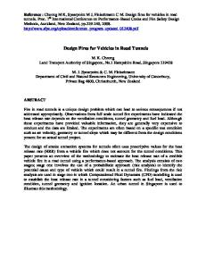
Exploration Drilling, Rock Consolidation Measures The passage of adverse geological zones with a double shield TBM may require exploration or probe drilling facilities respectively rock consolidation or rock supporting measures by means of surrounding “umbrella” grouting or mortar injected pipe roofing. The TBM has to be equipped in a way that an exploration range (40 – 100 m advancing) as well as an action range (1.5 – 2 D advancing) can be developed (Vigl et al., 1999) – Figure 7. The layout of that new universal double shield TBM contains three different possibilities in order to explore and to treat these a.m. ranges as well as the face area. A high-performance drilling equipment fitted on a drive carriage that is positioned on a guide ring at the TBM conveyor bridge allows 100 – 120 m advancing exploration drills through the shield within a 8° angle to the tunnel wall (exploration range, Figure 7). 37 guides along the perimeter incorporated in the gripper and telescopic shield enable efficient collaring at the tunnel wall. The lateral distance between the guides is about 150 mm in order to enable a sufficient rock support in case of roof piping for instance (Figure 7).
JÄGER BAU GMBH / GW SELI S.P.A. / PR
RETC 2003 PROCEEDINGS-REV.1
29/09/2003 16.14
10 A different fixture of the drilling unit within 18° angle to the tunnel wall allows corresponding measures at the action range respectively around the front section of the TBM. 28 guides are provided all around the tail shield (Figure 7). A small hydraulic rotary drill to be positioned right behind the cutter head enables to set 4 – 8 m long plastic anchors if any treatment of the face area will be required. As rock consolidation measures will serve corresponding injections or grouting. Rock supporting measures will be obtained by surrounding roof pipes (“umbrella”) with pressure grout. In case of collapsible ground casings will be used for the roof pipe drillings. In case of the required execution of roof pipes with an effective length of approx. 25 m an average production rate of about 3 m/day can be still assumed considering one drilling unit only. In case of a second drilling unit one could consider a daily production rate of about 4 m/day. That looks very poor but it can be deemed as a good production in zones, which could be not passed without “umbrella” even not by a double shield TBM.
THE UNIVERSAL DOUBLE SHIELD TBM IN COMPARISON
As a current standard of comparison the data of the double shield TBM´s not realized for the Swiss Gotthard base tunnel, lot Bodio East (∅ 9.4m) as well as the four 2002 built 9.5m double shield TBM´s for the Guadarrama Project in Spain has been considered. Both called projects are also railway tunnels like the Abdalajis tunnel. Further on, it has been considered the worldwide biggest double shield TBM´s, the 1994 built 11.75 m machines for the famous Pinglin project in Taiwan. As well known one of these two machines got lost so that there is only one TBM remaining at this road tunnel project. In order to emphasize the extraordinary capacity of the universal Abdalajis TBM and the similar Guadarrama TBM´s other recent mix shield TBM´s have been considered for a comparison as well. The machines „Westerschelde“ (∅ 11.34 m, Netherlands), „4. Röhre Elbtunnel“ (∅ 14.20 m, Germany) and „Groene Hart“ Machine (∅ 14.87 m, Netherlands) have been picked out. Figure 8 shows a comparison of the specific cutter head power related to the cross section. First of all one has to note the low cutter head power of the huge mix shield TBM´s (35% of the Abdalajis TBM only). The recent double shield hard rock TBM´s are close together. The specific cutter head power of JÄGER BAU GMBH / GW SELI S.P.A. / PR
RETC 2003 PROCEEDINGS-REV.1
29/09/2003 16.14
11 the Gotthard TBM is noticeably lower compared to the Abdalajis or Guadarrama TBM´s regardless of the much more severe geological requirements in terms of compressive strength and overburden. The Gotthard TBM had been specified as a pure hard rock TBM whereas the priority has been set up to an universal application range at the Abdalajis TBM. That means an application at soft rock with high friction forces as well as at hard rock. The layout of the Guadarrama TBM´s might have been influenced by the experience with EPB machines in Spain. The specific cutter head power of the Pinglin machines is about 60% of the Abdalajis TBM only. If one has a look to the specific torque which has been standardized with the effective radius respectively with the moment arm of 0.59 x R (NTH, 1994) – one compares the force developing the moment – one has to note that especially the Guadarrama TBM´s are very close to the naturally high torque rated mix shield TBM´s (Figure 9). Even the Abdalajis TBM is based high because of the intention to have a TBM for a wide range of application. The Pinglin as well as the Gotthard TBM´s are designed as pure hard rock TBM´s not requiring extraordinary torque values. Comparing the specific thrust forces in the end the Abdalajis TBM takes up an outstanding position (Figure 10). It has to be noted that at the double shield TBM´s the max auxiliary thrust at the exceptional hydraulic pressure had been considered. That exceptional auxiliary thrust will be applied in an emergency only when the double shield TBM has to operated in the single shield mode which is comparable at the earliest with the standard operation mode of a mix shield TBM. The Gotthard TBM´s are at the same level as the mix shield TBM´s. The specific auxiliary thrust of the Pinglin machines is only 40% compared to the Abdalajis TBM. This might be because of the fact that the machines for Taiwan had been designed a couple of years before already and on the other hand because of the designed max advance rate of 4.5 m/h only compared to 6m/h of the Abdalajis TBM. The intention for high thrust forces is of different nature. Mix shield or EPB machines require high thrust forces in order to dispose of corresponding thrust forces for the penetration in case of an active face support. The mix shield TBM for the 4th tube of the Elbe Tunnel in Hamburg (Germany) is designed for a back-pressure of 5 bar for instance. Such a back-pressure creates a load at the cutter head of about 80,000 kN (!). The max cutter head thrust of the 64 thrust cylinders is approx. 150,000 kN. That means for the real penetration force are 70,000 kN remaining only. JÄGER BAU GMBH / GW SELI S.P.A. / PR
RETC 2003 PROCEEDINGS-REV.1
29/09/2003 16.14
12 Hard rock TBM´s require high thrust forces in order to achieve corresponding penetration rates in hard rock and on the other hand in order to overpass zones of squeezing rock. Nevertheless especially the Abdalajis TBM marks an outstanding position and contains a remarkable potential in order to cross adverse and squeezing rock formations.
CONCLUSION
The layout of the universal double shield TBM for the Abdalajis project has been designed for an extraordinary wide range of application, which might be unique for the time being. To be honest for the present project there would be no need for such outstanding performance data. For further applications in railway tunneling there will be projects where such high performance reserves are required to achieve continuously high advance rates. Further it has to be noticed that this TBM concept is designed for up to 12 m diameter without changing any main components like main bearing, drive units, etc.
The main advantages of that new TBM can be summarized as follows: •
Extended application range
•
Outstanding torque capacity
•
Outstanding thrust capacity
•
Smooth shield arrangement
•
Shortest possible shield length
•
Extended exploration facilities
•
Diameter conversion (9.40 – 12 m)
The JV Abdalajis is convinced that an extremely efficient and forward-looking double shield TBM concept has been specified not only for Abdalajis but rather for future high speed railway tunnels (Figure 11). From August 2003 on it will turn out how successful that TBM concept will prove its worth in reality. JÄGER BAU GMBH / GW SELI S.P.A. / PR
RETC 2003 PROCEEDINGS-REV.1
29/09/2003 16.14
13
REFERENCES: Vigl, L. ; Gütter, W. ; Jäger, M. 1999: “Doppelschild-TBM – Stand der Technik und Perspektiven”, Felsbau 17 (1999).
N.N. 1994: “Hard Rock Tunnel Boring”. Project Report 1-94, of the University of Trondheim, the Norwegian Institute of Technology.
JÄGER BAU GMBH / GW SELI S.P.A. / PR
RETC 2003 PROCEEDINGS-REV.1
29/09/2003 16.14
AVE Railway Line `Cordoba – Malaga´ Tunel de Abdalajis 2 x 7 km Tunnel
Figure 1 Location of the project 1
10,98m Main Drive Unit
Guide Holes (Probe Drilling)
Rock Drill (Parking Pos.)
Main Thrust Cyl.
Cutterhead
Torque Cylinder Gripper Cyl.
Segment Erector
Auxiliary Thrust Cyl.
Figure 2 TBM Longitudinal Section 3
Cutter head
Sectional View Cutterhead Displacement Stabilizer Cyl.
Extended Buckets
CHD Displacement
Figure 3 Cutter head / Cutter head displacement 1
Figure 4 Muck Bucket Closure Doors 5
time dependence
pre-convergence
elasto-plastic convergences elastic
TBM
ca. 2,0 D
D
1 - 1.5 D
Figur 5 Elastic and Plastic Deformations during Excavation 6
185 mm 9.700 mm 115 mm
10.200 mm
10.000 mm
Figure 6 Schematic View of the Shield Arrangement 7
Exploration Range (40-100m advanced)
Action Range (1,5
37 Guide holes at 360° within the Gripper Shield
28 Guide holes at 360° within the Tail Shield
8° Inclination, DN 100
3 D)
18° Inclination, DN 100
Figure 7 Exploration Facilities 8
70 62
Hard Rock Double Shield TBM`s (diam. 9,40 - 11,75m) 59
60
51 50 37
24
2.400 kW
20 3.200 kW
20 3.500 kW
10
Mix Shield TBM´s (Single Shield, diam. 11,34 - 14,87m) 4.000 kW
3.550 kW
20
4.200 kW
30
4.900 kW
40
0 Abdalajis 2003
Guadarrama 2002
Gotthard (Bodio East) 2002
Pinglin 1995
Groene Hart 2001
4. Röhre Elbtunnel 1997
Westerschelde 1999
Project
Figure 8 Specific Cutterhead Power [ kW / m2 ] 9
Specific Cutterhead Torque at constant torque range (low speed) relative to effective moment arm [0,59 x D/2] 12.000
Hard Rock Double Shield TBM´s (diam. 9,40 - 11,75m)
9.848
7.395 43.200 kNm
6.339
Guadarrama 2002
Gotthard (Bodio East) 2002
0 Abdalajis 2003
2.077 7.200 kNm
3.295 9.100 kNm
20.700 kNm
2.000
18.700 kNm
6.000
Pinglin 1995
Groene Hart 2001
6.207 4.484
4. Röhre Elbtunnel 1997
15.000 kNm
8.000
4.000
Mix Shield TBM´s (Single Shield, diam. 11,34 - 14,87m)
26.000 kNm
10.000
Westerschelde 1999
Project
Figure 9 Specific CHD Torque [ kNm/m ] 10
Max. Exceptional Specific Auxiliary Thrust (cross section) 2.500
Hard Rock Double Shield TBM´s (diam. 9,40 - 11,75m) 1.942
120.700 kN
947
150.000 kN
726
184.300 kN
1.061
1.023
78.700 kN
500
1.195
70.600 kN
152.500 kN
1.000
Mix Shield TBM´s (Single Shield, diam. 11,34 - 14,87m)
1.433
1.500
101.250 kN
2.000
0 Abdalajis 2003
Guadarrama 2002
Gotthard (Bodio East) 2002
Pinglin 1995
Groene Hart 2001 4. Röhre Elbtunnel 1997
Westerschelde 1999
Project
Figure 10 Specific Auxiliary Thrust [ kN/m2 ] 11
Figure 11 A forward-looking Double Shield Concept for future Highspeed Railway Tunnels 12
• • • • • • • • • • • • •
Excavation Diameter Avg. / max. Advance Rate CHD Installed Power CHD Speed CHD Torque (constant range) CHD Torque (max. Speed) Breakout Torque (0-5Hz, max. 60s) Number of Disc Cutters (17“, 267kN) Max. Main Thrust Max. Auxiliary Thrust Total Installed Electric Power Shield Length Total Weight
10,00 – 10,20 m 3,75 / 6,00 m/h 4.900 kW (14 x 350 kW) 0 – 6 rpm 18.700 kNm (0-2,5 rpm) 7.800 kNm (6 rpm) 28.000 kNm 64 + 5 Overcutter 82.500 kN (410 bar) 152.500 kN (450 bar) 5.778 kW 10,98 m 1.300 to
Table 1 Main characteristics of the 10m Universal DS-TBM 2