Neo-Geo Programming Manual check regularly http://groups.yahoo.com/group/ngdev for updates. This version is unfinished and has some known and of course unknown errors. It was published in this early state to encourage interested developers in Neo-Geo programming. Author: Alexander Stante (aka Pa-Pa-Panic!! / Mr.Pac) email:
[email protected]
2
Table of Contents 1 Introduction..................................................................................................................................... 3 1.1 Legal Notice...............................................................................................................................3 1.2 A short Overview.......................................................................................................................3 1.3 Revision History........................................................................................................................ 3 2 The Neo-Geo System....................................................................................................................... 4 2.1 System Overview....................................................................................................................... 4 2.2 NEOGEO CPU's........................................................................................................................ 4 2.2.1 Motorola MC68000 - The Main CPU................................................................................4 2.2.2 Zilog Z80 - Sound CPU..................................................................................................... 5 2.3 Memory......................................................................................................................................5 2.4 Display....................................................................................................................................... 5 2.5 Operation................................................................................................................................... 5 2.6 Sound......................................................................................................................................... 5 2.7 Other Devices............................................................................................................................ 6 3 Memory.............................................................................................................................................7 3.1 Overall Memory Map MC68000............................................................................................... 7 3.2 Overall Memory Map Z80......................................................................................................... 9 4 Graphics System............................................................................................................................ 11 4.1 Fix Layer.................................................................................................................................. 11 4.1.1 Fix Layer Map.................................................................................................................. 11 4.1.2 Fix Layer Data Format..................................................................................................... 12 4.1.3 Fix Layer Character Set....................................................................................................12 4.2 Sprites...................................................................................................................................... 12 4.3 Color Palettes...........................................................................................................................14 4.3.1 Color Palette RAM...........................................................................................................14 4.3.2 Color Palette Banking...................................................................................................... 14 4.3.3 Color Data Format............................................................................................................14 5 Memory-Mapped Registers.......................................................................................................... 15 6 NEOGEO System Calls.................................................................................................................23 7 Sound.............................................................................................................................................. 24
1
Introduction
The idea for this document came across after trying to write some line of code for the Neo-Geo. In comparison to the Nintendo Game Boy Advance (GBA) there is almost no detailed information about the Neo-Geo hardware available and development tools are also rare to find. Furthermore, I have also the plan to release some develpment software for the Neo-Geo and therefore I thought that it could be usefull to collect some informations about the hardware in one document. The design of the document is inspired from the "CowBite Virtual Hardware Specification" for the GBA. If you are looking for some NEOGEO programming tutorials you are currently wrong here. This document is a reference manual, but maybe I will add some tutorial in future. I am a newbie in NEOGEO programming and this is my first project where I collect some informations and do some reverse engineering. It is quite possible that the document is full of errors, because I havn't tested everything in this document and I also added conclusions which only base on intuition :) I am also allways busiy so I don't have to much time to spend working on this document. If you have found some errors, typos or missing stuff, don't hesitate to
[email protected]
1.1
Legal Notice
NEOGEO is a registred trademark of SNK PLAYMORE CORPORATION. Some informations of this document are from the MAME source although the comments are a bit frugal used along the source.
1.2
A short Overview
The NEOGEO is a quite interesting architechture. It consists of a Motorola MC68000 main CPU and a Z80 for sound. Like many 2D (arcade) machines the graphics hardware is tile based to save ROM space and to support hardware manipulation of the 2d entities. The Z80 is connected with a YM2610 sound chip to produce sound. The MC68000 communicates throug a Memory Mapped I/O register with the Z80. As far as my observations go, the MC68000 just says what soundtrack or sample should be played, the rest is handled by the Z80. Another interesting aspect is the memory layout of the NEOGEO. The MC68000 has only acceess to the program roms (with use of bankswitching of course), the working RAM and some other regions which are shown in the Memory section of this document. The whole character data (graphic) is not visible for the MC68000. Only the graphics system has access to this one, so you cannot manipulate the graphics itself. The same counts for the sounds roms. The main CPU has no access to this roms, only the Z80 has. This distributed memory layout is the reason that the NEOGEO roms can be so huge although the main CPU has only a 24 bit wide address bus.
1.3
Revision History
2
The Neo-Geo System
2.1
System Overview
The NEOGEO is a gaming platform with propably the highest installation base in arcades ever. Furthermore there is also a home consumer version of the NEOGEO. Through this document the arcade version of the NEOGEO will be refered as MVS and the home consumer versions as NGH. Due the different requirements of arcades and in order to reduce production costs there are many different versions of the MVS available. The following table gives you a short overview about the currently known versions of the MVS with some detailed information follows: • NEOGEO MV-1 • NEOGEO MV-1A • NEOGEO MV-1B • NEOGEO MV-1C • NEOGEO MV-1F • NEOGEO MV-1FZ • NEOGEO MV-2F • NEOGEO MV-4F • NEOGEO MV-6F • 1.2 NEOGEO CPU's
2.2
NEOGEO CPU's
As you propably already know, the NEOGEO has two CPU's. One is the Motorola MC68000, the other one is the Zilog Z80. In this section I want to give you a short overview about the two CPU's. Usually the MC68000 is the important part, even SNK PLAYMORE does not write new Z80 code for every new game. I don't want to give you an introduction about how to program this CPU's because this is out of the scope of this document. If you want to learn programming these CPU's I suggest buying a book or looking for some documents about it on the Internet.
2.2.1
Motorola MC68000 - The Main CPU
The Neo-Geo uses a MC68000 which runs at a clock speed of 12Mhz. Now I list some features about the CPU found on motorolas website: 32 Bit Data and Address Registers 16 MByte Direct Addressing Range 56 Powerful Instructions
2.2 NEOGEO CPU's
5
Memory Mapped Input/Output 14 Addressing Modes 2 MIPS at 20MHz The CPU is a CISC (Complex Instruction Set Computers) architecture.
2.2.2
Zilog Z80 - Sound CPU
The other CPU in the Neo-Geo is the Z80. It is a 8bit processor and runs at a clock speed of 4Mhz. More will be added soon! Currently I focus on the rest of the hardware and writing development tools
2.3
Memory
System ROM 128 Kbytes (including System Fix ROM) Working RAM 64 Kbytes VRAM 64 Kbytes (propably even a little bit more, some research needed) Palette RAM 8192 Kbytes (the exact number of colors seems to be 4096 (bankswitching?)) Program ROM 5 Mbytes (1 Mbyte + 4 Mbytes bankswitchable ROM) Character ROM 64 Mbytes (8 x 8 Mbytes ROM) Sound ROM 16 Mbytes (4 x 4 Mbytes ROM) Fix ROM 4 Mbytes? 16 bit index and propably 64 bytes per tile.
2.4
Display
It seems that the NEOGEO supports two resolution modes, one is 320 x 224 and the other is 304 x 224 (garou?). The graphics processing circuit supports 384 hardware rendered sprites from a size of 16x16 to 16x512 (it is not accurate, theoretically it should be more pixels in width because you can join the many 16 pixel width sprites together). This sprites are also able to be hardware scaled. Contrary to common claim the NEOGEO does not support zooming. The often noticed zoom effect is in fact a big sprite which is scaled. Additionally to this moveable sprites the NEOGEO does support a fix layer which is a layer where tiles can be aligned in a fixed grid. This layer is often used for game status informations like available credits and on-screen game informations like health, time and so on.
2.5
Operation
The NEOGEO has two joystick inputs with both stick having A, B, C, D, START, SELECT (COIN), and Direction Stick.
2.6
Sound
The sound part of the NEOGEO consists of a Z80 which is running some kind of sound driver. The
2.6 Sound
6
Z80 uses a Yamaha YM2610 for sound output. Through this chip the NEOGEO supports 4-FM synthesis, 7-Digital, 3-PSG and 1-Noise channels. It should be theoretically possible to increase the number of channels by writing a Z80 driver that can mix channels in software (that kind of technique is for e.g. used in GBA sound programming), but maybe this is exactly what the current sound driver are doing. The following table is a list of the different generic sound driver which were used until now: • AF Sound (v1.0, v1.1, v1.2, v1.3) • Makoto (v2.0a, v3.0, v8.3) • MrPac (v1.5b, v2.0) • OS (v1.2, v2.2, v3.5, v6.4, v6.5, v7.3, v8.4, v8.5, v8.7.8, v8.8a, v8.8.7, v8.8.9, v8.8.11) • Sound Driver (v0.0, v0.1, v1.0, v1.1, v1.3, v1.6, v1.7, v1.8)
2.7
Other Devices
Additionally the NEOGEO has a Memory Card Slot (NGH integrated) and a Battery Backed Serial I/O Calender Controler (MVS Only). The Memory Card is used for saving the game state and it is even possible to exchange them between the NGH and MVS. The Battery Backed Serial I/O Calender Controler is used for the MVS only book keeping system.
3
Memory
The following is a generall descriptions of the different memory areas seen by the two CPU. The 64 Kbytes VRAM are not directly, but only through Memory Mapped I/O accessable. It seems that different bankswitching schemes are used which depends on the current cartrigde implementation. Furthermore the bankswitching of program code and graphics data is seperated.
3.1
Overall Memory Map MC68000
The following is the overall memory map of the NEOGEO Motorola MC68000 main CPU. ROM Bank 1 Start: 0x000000 End: 0x0fffff Size: 1MB The Program ROM is mapped into this area. Many games have a 1MB big P1 rom which is loaded into this area. Although the NeoGeo supports rom bankswitching, it seems that no game does bankswitching on this bank. I don't know if it is technically not possible, or it is too difficult for the NEOGEO developer to create location / bank independent code. RAM Bank Start: 0x100000 End: 0x10ffff Size: 64KB Many games set the SP to 0x10f300. The area above this address seems to be used by BIOS. For e.g. BIOS call 0xc0044a saves controller positions and much more in this area. ROM Bank 2 Start: 0x200000 End: 0x2fffef Size: 1MB
3.1 Overall Memory Map MC68000
8
This is the second ROM bank. My guess is that data structures and variables are stored in this bank, due the fact I never seen the PC reaching this location. Many newer games use heavily bankswitching to access this data. It seems that a maximum of 4 banks can be accessed through this address range. Another interesting observation is that the mapped banks have some kind of header. KOF98 and Garou for e.g seemed to save the bank number to 0x200001. Bankswitch RAM Start: 0x2ffff0 End: 0x2fffff Size: 2Bytes Some documents talk about Bankswitch write instead of Bankswitch RAM. Maybe it is only possible to write data into this are and not to read from. My latest observations lead to another conclusion. It seems that this is in fact not RAM but just bankswitch write. Furthermore it seems that the correct address is 0x2fffe0. I guess that the word for selecting the correct bank depends on the wireing of the cart and is not machine depending. Memory-Mapped Hardware Registers Start: 0x300000 End: 0x3fffff (??) Size: 1MB Palette RAM Start: 0x400000 End: 0x401fff Size: 8KB Memory Card RAM Start: 0x800000 End: 0x800fff Size: 4KB The Memorycard consits of 2KB battery backed RAM. The even bytes are always 0xFF, just the odd bytes consists of data.
3.1 Overall Memory Map MC68000
9
System Bios ROM Start: 0xc00000 End: 0xc1ffff Size: 128KB SRAM Start: 0xd00000 End: 0xd0ffff Size: 64KB This area contains the onboard 64kb battery backed SRAM. It is used for saving different cabinet and game informations/settings.
3.2
Overall Memory Map Z80
The following is the overall memory map of the NEOGEO Zilog Z80. ROM Bank 1 Start: 0x0000 End: 0x7fff Size: 32KB Seems that the sound Program ROM runs in this area. ROM Bank 3 Start: 0x8000 End: 0xbfff Size: 16KB Bankswitchable with port 0x0b ROM Bank 4 Start: 0xc000 End: 0xdfff
3.2 Overall Memory Map Z80 Size: 8KB Bankswitchable with port 0x0a ROM Bank 5 Start: 0xe000 End: 0xefff Size: 4KB Bankswitchable with port 0x09 ROM Bank 6 Start: 0xf000 End: 0xf7ff Size: 2KB Bankswitchable with port 0x08 RAM (Bank 2?) Start: 0xf800 End: 0xffff Size: 2KB
10
4
Graphics System
The Neo-Geo graphics system is like the most of the successful 2D machines tile based, which means that you don't manipulate VRAM like a framebuffer but you work mainly with refrerences to tiles in ROM. This references are stored in so called maps in VRAM. An entry of the map does not only consists of a reference to the character data in ROM but also consists of some additional attributes like what palette should be used, the position and so on. I want to stress again that no character data is stored in VRAM. The VRAM is not directly addressable by the CPU, there are three memory mapped I/O registers which are used to manipulate data in VRAM. The addresses used are REG_VRAMLOC (0x3c0000) where the read/write location is set, then the REG_VRAMINC (0x3c0004) where you can set the autoincrement value for reading/writing and finally REG_VRAMRW (0x3c0002) where you can read/write the data in VRAM at the position set at REG_VRAMLOC. After each write or read the REG_VRAMLOC points to the position incremented by REG_VRAMINC. Note that the VRAM is half-word (16 bit) addressed and not byte addressed like the M68000 memory. The graphics system consists of three main parts, which are the Fix Layer, Sprites and Color Palettes. The first two are stored in VRAM and on board or cartridge ROM, while the Color Palettes are stored at an other memory location which is directly addressable. There is no special background layer. Background layers are made of aligned sprites. The benifit is that you are quite more flexible to use the available memory.
4.1
Fix Layer
The fix layer is a layer of 8 x 8 dot big tiles which is not moveable. Usually it is used to display some game informations like credits, lives and so on. In this layer only the first 16 palettes can be used, which is a total of 256 colors. The Fix Layer contains mainly of two parts, the Fix Layer Map, which is stored in VRAM and the Fix Character Set, which is stored in ROM either on Neo-Geo or in the cartridge itself. You can select the board or cartridge Character Set by writing to the following addresses: Address
Character Set
0x3a000a Board Character Set 0x3a001a Cartridge Character Set Table 4-1: Character Set selection
4.1.1
Fix Layer Map
The map is stored from 0x7000 - 0x74FF in VRAM. The VRAM is addressed in half-word size, so actually 2560 bytes of space is in this area. Each entry is 16 bit wide and consists of a index of
4.1 Fix Layer
12
the used palette and a index of the used tile in the Character Set. The following table shows the alignment of the Fix Layer Map in VRAM. The first and last line are not shown by the Neo-Geo, because they are outside of the displayable area. 0
1
2
3
...
36
37
38
39
0 0x7000 0x7020 0x7040 0x7060
0x7480 0x74A0 0x74C0 0x74E0
1 0x7001 0x7021 0x7041 0x7061
0x7481 0x74A1 0x74C1 0x74E1
2 0x7002 0x7022 0x7042 0x7062
0x7482 0x74A2 0x74C2 0x74E2
3 0x7003 0x7023 0x7043 0x7063
0x7483 0x74A3 0x74C3 0x74E3
... 28 0x701C 0x703C 0x705C 0x707C
0x749C 0x74BC 0x74DC 0x74FC
29 0x701D 0x703D 0x705D 0x707D
0x749D 0x74BD 0x74DD 0x74FD
30 0x701E 0x703E 0x705E 0x707E
0x749E 0x74BE 0x74DE 0x74FE
31 0x701F 0x703F 0x705F 0x707F
0x749F 0x74BF 0x74DF 0x74FF
Table 4-2: Fix Layer Map
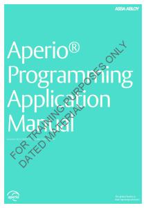
There is a invisible border around the the Fix Layer. As seen in the table above Fix Layer is 40x32 tiles big, which is equivalent to a resolution of 320 x 256. The Neo-Geo resolution is a bit smaller, it has 304 x 224, which is equivalent of 38 x 28 tiles. Therefore there is a 2 tile broad border at the top and botton and a 1 tile big invisible border on the left and right side, as shown it the picture below. The upper left tile is stored at address 0x7022.
Picture 4.1: Visible Fix Layer tiles
4.1 Fix Layer
4.1.2
13
Fix Layer Data Format
Each entry in the Fix Layer Map has the following format. F E D C B A 9 8 7 6 5 4 3 2 1 0 P
P
P
P
I
I
I
I
I
I
I
I
I
I
I
I
0-B (I): Character Index C-F (P): Color Palette The Color Palette field is 4 bit wide, so you can address the first 16 palettes with this value, the Character Index is the index which of the 32 bytes big characters should be used. The character is addressed in the Character Set with the formula: Address = Character_Index * 32.
4.1.3
Fix Layer Character Set
Each tile in the Fix Layer Character Set needs 4 bits for each pixel, which sum up to 32 bytes big tiles. 4 bits per pixel are used because each palette has 16 colors. With the 12 bit big Character Index field in the Fix Layer Data Format a maximum of 212 (4096) tiles can be stored in the Character Set. This leads to a maximum size of 128 kb of the Character Set. The format how the character data is stored is shown in the table below. Each byte represents two pixels. The leftmost pixel is saved on the lower nibble of the byte. 0+1
2+3
4+5
6+7
0
a(n+0x10) a(n+0x18) a(n+0x0) a(n+0x8)
1
a(n+0x11) a(n+0x19) a(n+0x1) a(n+0x9)
2
a(n+0x12) a(n+0x1A) a(n+0x2) a(n+0xA)
3
a(n+0x13) a(n+0x1B) a(n+0x3) a(n+0xB)
4
a(n+0x14) a(n+0x1C) a(n+0x4) a(n+0xC)
5
a(n+0x15) a(n+0x1D) a(n+0x5) a(n+0xD)
6
a(n+0x16) a(n+0x1E) a(n+0x6) a(n+0xE)
7
a(n+0x17) a(n+0x1F) a(n+0x7) a(n+0xF)
Tabelle 4-3: Character Data Format
4.2
Sprites
The NEOGEO Sprite system is a bit unconventional implemented and the character data for the sprites are quite confusing stored. But every thing, step by step. The Sprites are made of 16 x 16 dot bit tiles. Every tile can has it own pallete so a quite huge amount of colors can be used. But as you just noticed, a tile can only have 16 colors, although it is made of 16 x 16 pixels. There are different sizes of sprites available, which are starting from 16 x 16 and end up in 16 x 512. All sprites are fixed at a width of 16 pixels (one tile) and can build a column of at most 32 tiles. But there is a nice feature that allows you to join some sprites to one bigger (wider) sprite. Each sprite has a Join Flag and if it is set it is positioned right besides the previeous sprite. Previous
4.2 Sprites
14
means in this case the sprite at the memory address just before in a growing address space. So if you move a sprite, all following sprite which have the Join Flag set will move according to it. Furthermore the Sprite System allows you to flip and scale sprites. For setting all the attributes to sprites there are 4 regions in memory responsible. This regions are called Sprite Control Block and will from now on just called SCB.
4.2.1
Sprite Attributes
Sprite attributes are stored at four different memory locations called Sprite Attribute Blocks. The attributes are used to set the size of the sprites, position, scaling factor and much more. With the use of REG_VRAMINC you can quite effectively write the different attributes. 0x0000 – 0xdfff Sprite Attribute Block 1 (SAB1)
SAB1 is used to set the tiles from which a sprite is composed. The memory location for this attribute is from 0x0000 – 0xdfff in VRAM. The attributes for each tile The size if the sprite is at least 16 x 16 pixels (1 x 1 tiles) and at most 16 x 512 pixels (1 x 32 tiles). The sprite data is stored at the 4 Sprite Control blocks. Each entry of the SCB1 is made of two half-words. The first one stores the number of the first tile, the next half-word stores some attributes of the tile like x/y flip, destination bank and very important the palette number. Each tile can has it own palette, it is not limited to sprite. As I mentioned before, a sprite can has a at most the size of 16x512 pixels or 1x32 in tile space. So each sprite entry is 32*(1_HW + 2_HW) bit which are 128 bytes. Because of the half-word addressed video memory the addresses for the Sprites are SPR0 = 0x0000, SPR1 = 0x0064, SPR2 = 0x0128, ..., SPR ?????????????????? 0x0000 - 0xdfff: Sprite Control Block 1 15
14
13
12
11
10
9
8
7
6
5
4
3
2
1
0
4
3
2
1
0
15
14
13
12
11
10
9
Palette Number
8
7
C
6
5
DBS
XFE = X-Flip Enable YFE = Y-Flip Enable DBS = Destination Bank Select 0-F (N): Character Name FEDC BA98 7654 3210 NNNN NNNN UMMM ABYX 0 (X) = X flip 1 (Y) = Y flip
B A
YFE XFE
Character Name
A = Unknown (Auto Animation?) B = Unknown (Auto Animation?) C = Unknown
4.2 Sprites
15
2-4 (M) = destination bank with sprites 7 (U) = unknown, maybe not used? 8-F (N) = palette number
0x8000 - 0x81FF: Sprite Control Block 2 FEDC BA98 7654 3210 UUUU XXXX MMMM YYYY 0-3 (Y) = Y zoom of sprite 4-7 (M) = unknown, some documents say something about "Y zoom MSB" 8-B (X) = X zoom of sprite C-F (U) = unknown, probably unused 0x8200 - 0x83FF: Sprite Control Block 3 FEDC BA98 7654 3210 YYYY YYYY YFNN NNNN 0-5 (N) = number of tiles in sprite 6 (F) = join flag, if set sprite is placed right to previous sprite A-F (Y) = Y position of sprite 0x8400 - 0x85FF: Sprite Control Block 4 FEDC BA98 7654 3210 XXXX XXXX XFNN NNNN 0-5 (N) = unknown 6 (F) = unknown A-F (Y) = X position of sprite
4.3
Color Palettes
The Neo-Geo can display 32 levels of red, 32 levels of green, and 32 levels of blue, for a total of 32.768 colors.
4.3 Color Palettes
16
Color 0 is the transparency
4.3.1
Color Palette RAM
The palette is stored in the memory area 0x400000 - 0x401FFF. A total 4096 colors can be stored at this area, which is equivalent of 256 color palettes with each 16 colors.. Every color uses 16 bit of data and is saved in RGB order.
4.3.2
Color Palette Banking
The palette is banked, which means that you have actually two palette banks with each 4096 colors, but you can only use one at once. You can select between the palette banks by writing to the following addresses: Address
Palette Bank
0x3a000e Palette Bank 1 0x3a001e Palette Bank 0 Table 4-4: Palette selection
4.3.3
Color Data Format
Allows 1 of 32.768 colors to be specified.
5
Memory-Mapped Registers
The following section describes the function and use of the memory-mapped hardware registers. The first part of the section is a overview about the available addresses. 0x300000 - REG_P1CNT 0x300001 - REG_DIPSW 0x300080 - REG_UNKNOWN 0x300081 - REG_UNKNOWN 0x31001c - REG_UNKNOWN 0x320000 - REG_SOUND 0x320001 - REG_STATUS_A 0x340000 - REG_P2CNT 0x380000 - REG_STATUS_B 0x380030 - REG_UNKNOWN 0x380040 - REG_UNKNOWN 0x380051 - REG_SCLKCMD 0x380060 - REG_UNKNOWN 0x3a0001 - REG_DISPENABL 0x3a0003 - REG_SWPBIOS 0x3a000a - REG_BRDFIX 0x3a000c - REG_SRAMLOCK 0x3a000e - REG_PALBANK1 0x3a0011 - REG_DISPDSABL 0x3a0013 - REG_SWPROM 0x3a001a - REG_CRTFIX 0x3a001c - REG_SRAMULOCK 0x3a001e - REG_PALBANK0 0x3c0000 - REG_VRAMADR 0x3c0002 - REG_VRAMRW 0x3c0004 - REG_VRAMINC 0x3c0006 - REG_HBLANKCNT 0x3c0008 - REG_HBLANKPOS
5 Memory-Mapped Registers
18
0x3c000c - REG_IRQACK Address: 0x300000 - REG_P1CNT (Key Control Register) Address: 0x340000 - REG_P2CNT (Key Control Register) RRRR RRRR 7654 3210 DCBA RLWU 0 (U) = D-Stick Up 1 (W) = D-Stick Down 2 (L) = D-Stick Left 3 (R) = D-Stick Right 4 (A) = A Button 5 (B) = B Button 6 (C) = C Button 7 (D) = D Button This register is active on LOW, which means that the bits are cleared when a certain button or direction is pressed. For checking pressed Start or Select buttons check REG_SYSSTAT. Writing to REG_P1CNT leads to watchdog reset. Address: 0x300001 - REG_DIPSW (Hardware DIP Switch) RRRR RRRR 7654 3210 PFCC CORS 0 (S) = Setting Mode 1: Game Mode
0: Test Mode
1 (R) = Controller Type 1: Normal Controller
0: Mahjong Controller
2 (O) = Coin Switch (???) 3-5 (C) = Communication Plays (maybe something to do with link games?) 6 (F) = Free Play 7 (P) = Stop Mode This register mapps the hardware dip settings into RAM. Like REG_P1CNT they are active on
5 Memory-Mapped Registers
19
LOW. The information about the settings are directly taken from MVS documents and differs to the informations from the MAME emulator. Address: 0x300080 - REG_UNKNOWN (???) FEDC DA98 7654 3210 AAAA AAAA AAAA AAAA 0-F (A) = unknown Mame source says "Controller #4 - Test switch in here". Purpose unknown to me. Address: 0x300081 - REG_UNKNOWN (???) FEDC DA98 7654 3210 AAAA AAAA AAAA AAAA 0-F (A) = unknown The value of this register is 0xC0, purpose unknown. In mame the register above and this one are together handled. Address: 0x31001c - REG_UNKNOWN (???) FEDC DA98 7654 3210 AAAA AAAA AAAA AAAA 0-F (A) = unknown (ghost pilots) Address: 0x320000 - REG_SOUND (Z80 Sound) FEDC DA98 7654 3210 AAAA AAAA AAAA AAAA 0-F (A) = Sound value This register is used to communicate with the Z80 CPU. Games are writing some indexes into this address which are later processed by the Z80 CPU. The whole music handling code is in Z80 rom code, the MC68000 just selects certain tracks and sound effects through this register. Address: 0x320001 - REG_SYSSTAT_A (System Status A)
5 Memory-Mapped Registers
RRRR RRRR 7654 3210 XPXX XCBA 0
(A) = Coin 1
1
(B) = Coin 2
2
(C) = Service
3-5 (X) = Unknown 6
(D) = NEC D4990 time pulse
7
(E) = NEC D4990 data bit
Bits 0-2 are active on LOW. Address: 0x380000 - REG_SYSSTAT_B (System Status B) RRRR RRRR 7654 3210 XPMM DCBA 0 (A) = Player 1 Start 1 (B) = Player 1 Select 2 (C) = Player 2 Start 3 (D) = Player 2 Select 4-5 (M) = Memory Card inserted 6 (P) = Memory Card write protected 7 (X) = Unused Register is active on LOW. (Writing to this register selects trackball?) Address: 0x380030 - REG_UNKNOWN (???) FEDC DA98 7654 3210 AAAA AAAA AAAA AAAA 0-F (A) = unknown Used by bios, unkown
20
5 Memory-Mapped Registers
21
Address: 0x380040 - REG_UNKNOWN (???) FEDC DA98 7654 3210 AAAA AAAA AAAA AAAA 0-F (A) = unknown Enable output leds? Address: 0x380051 - REG_SCLKCMD (Serial I/O Real Time Clock Parallel Command) 7654 3210 XXXX XCCC 0-2 (A) = Command 000 = Register hold
100 = Set Timing Pulse to 64Hz
001 = Register shift
101 = Set Timing Pulse to 256Hz
010 = Time set and data hold 110 = Set Timing Pulse to 2048Hz 011 = Time read
111 = Serial command transfer mode
3-7 (X) = Unused This register is used to set parallel commands to the NEC D4990A Serial I/O RTC. The last two bits of REG_SYSSTAT2 are also used for controlling the NEC D4990A. Address: 0x380060 - REG_UNKNOWN (???) FEDC DA98 7654 3210 AAAA AAAA AAAA AAAA 0-F (A) = unknown Used by bios, unkown Address: 0x3a0001 - REG_DISPENABL (Display Enable) Address: 0x3a0011 - REG_DISPDSABL (Display Disable) Write any value to this registers to enable or disable the display.
5 Memory-Mapped Registers
22
Address: 0x3a0003 - REG_SWPBIOS (Swap in BIOS Vector Table) Address: 0x3a0013 - REG_SWPROM (Swap in ROM Vector Table) Write to this registers to swap in the BIOS vector table or the cartridge ROM vector table (first 128 bytes). Address: 0x3a000a - REG_BRDFIX (Select Board FIX ROM) Address: 0x3a001a - REG_CRTFIX (Select Game FIX ROM) Select the FIX ROM which is onboard, or the one which is in the cartridge. Address: 0x3a000c - REG_SRAMLOCK (SRAM Lock) Address: 0x3a001c - REG_SRAMULOCK (SRAM Unlock) Locks/Unlocks the NeoGeo SRAM (Backup RAM?) Address: 0x3a000e - REG_PALBANK1 (Palette Bank 1) Address: 0x3a001e - REG_PALBANK0 (Palette Bank 0) Selects the Palette Bank. After powerup bank 0 is selected by default. Address: 0x3c0000 - REG_VRAMAD (VRAM Address) FEDC DA98 7654 3210 AAAA AAAA AAAA AAAA 0-F (A) = Current VRAM address to read from or write to. This register is used to set the location to read/write through REG_VRAMRW. Furthermore if you read from this register you obtain the same data as reading from REG_VRAMRW. After setting the location, it is not possible to read the current location. After a read or write this register is incremented by REG_VRAMINC. Attention, the VRAM is word addressed!! Address: 0x3c0002 - REG_VRAMRW (VRAM Read/Write) FEDC DA98 7654 3210 AAAA AAAA AAAA AAAA
5 Memory-Mapped Registers
23
0-F (A) = Read/Write VRAM. This register is used to read/write VRAM at the location set in REG_VRAMLOC. Address: 0x3c0004 - REG_VRAMINC (VRAM Increment) FEDC DA98 7654 3210 AAAA AAAA AAAA AAAA 0-F (A) = Increment value of VRAM access. This register sets the increment value for VRAM access. After accessing the VRAM through REG_VRAMRW the REG_VRAMLOC will be set to REG_VRAMLOC + REG_VRAMIC. Address: 0x3c0006 - REG_HBLANKCNT (HBlank Interrupt Control) 7654 3210 CBRE AXXX 0-2 (X) = Unknown (Maybe something to do with auto animation?) 3 (A) = Stops auto animation counter 4 (E) = Enable HBlank Interrupt (IRQ2), which is triggered after a certain scanline is reached 5 (R) = If set, the next interrupt will be triggered REG_HBLANKPOS lines later than the current one 6 (B) = REG_HBLANKPOS will automatically be loaded during VBlank 7 (C) = Every time HBlank interrupt occurs the REG_HBLANKPOS will be loaded Address: 0x3c0008 - REG_HBLANKPOS (HBlank Interrupt Position Trigger) FEDC BA98 7654 3210 AAAA AAAA AAAA AAAA
0-F (A) = Position to trigger HBlank interrupt Address: 0x3c000c - REG_IRQACK (Interrupt Acknowledge) 7654 3210
5 Memory-Mapped Registers
24
XXXX XBAX 0 (X) = Unused 1 (A) = VBlank IRQ clear 2 (B) = HBlank IRQ clear 3-7 (X) = Unused Purpose unkown. My guess is that this is used to prevent nested IRQ calls. After clearing the next IRQ will be processed.
6
NEOGEO System Calls
The System calls are made by simply jumping into the Bios vector table. The table resides in the are from 0xc00402 - 0xc004d4 (not proofed). The vector entries are 6 bytes wide. The following addresses are all offsets from 0xc00000 0x402: Entry Point This Bios function is called on startup. Every game I currently saw sets the initial PC (0x000008 in ROM) to this Bios call. 0x408: Entry Point 0x40e: Entry Point 0x414: Entry Point 0x41a: Entry Point 0x420: Entry Point 0x426: Entry Point 0x42c: Entry Point 0x432: Entry Point 0x438: Display Startup Logo It seems that this call is responsible for the NeoGeo Startup logo. It is called every VBLANK (set in the VBLANK routine) until logo display is finished. But maybe it is responsible for something else too, because the BIOS calls this function at the end of the memory test some times. 0x43e: ?? It is unknown what this call exactly does. In the Bios header it is set as the HBLANK call. 0x44a: ?? This function is called by many (all?) Games during VBLANK interrupt. It copies the controller position and some other values into RAM. 0x4c2: ?? Baseball Stars 2 calls this function after inserting 2 credits. Used Memory addresses (by Bios?) 0x10fd84 - 0x10fd93: This area holds the game settings that are set by Neo Geo Bios Soft Dip Settings. The format depends on the current menu configuration set by the game. The first 4 bytes contains the value of the "Time" menu item. The following bytes contains a index of the selected value in menu.
7
Sound
The following section describes the funcion of the Z80 which are accessable through reading from and writing to ports. Reading: 0x00 = Soundlatch (0) 0x04 = YM2610 statusport 0 A 0x05 = YM2610 readport 0 0x06 = YM2610 statusport 0 B 0x08 = Bankswitch 0x09 = Bankswitch 0x0A = Bankswitch 0x0B = Bankswitch See memory map for futher information about bankswitching Writing: 0x04 = YM2610 controlport 0 A 0x05 = YM2610 dataport 0 A 0x06 = YM2610 controlpot 0 B 0x07 = YM2610 dataport 0 B 0x08 = NMI enable / acknowledge ? 0x0c = result code = data 0x18 = NMI disable ?
7 Sound
27