Wisely Laser Machinery Limited 7F, Building 7th, JSC Industrical Area, Jingnan Road, Buji Street, Shenzhen 518112 China T: 0086-151 0755 0219 F: 0086-755-2857 9476 Email:
[email protected] www.wwlaser.com; www.wisely-laser.com; Skype/MSN: wwlase
MY-L6090 Laser Engraving & Cutting Machine Dear Customers: Thanks for choosing our MY-L6090 Laser engraving and cutting machine. Please read this instruction carefully before using, it is helpful for your operation.
Our aim is continuous improvement and improving existing products. So, maybe the machine is differing from the instruction. If there is going to be some change, we will tell you by attached sheet. We regret any inconvenience. Please contact our After-sale service department if you need any help, we will try our best to meet your requirement.
Because the I/O, laser power or laser tube is electrical, please be more careful when you operate the machine to avoid electrical shock., pay attention to the personal safety.
State This instruction book is protected by copyright law, the international copyright treaties and applicable laws.
Please don’t copy any content of it without permitted. Abide by the
sustainable development principle; we may amend this instruction book when necessary without any notice.
I
The manual introduced how to install, use, process and maintain the laser engraving machine in detail. Before unpacking and using the machine, please pay attention to the following points:
The operator should have relevant technical training, or supervised by the specially-assigned person.
The manual will help you know and process the machine in accordance with rules and regulations.
Many important tip included in the manual will help you process the machine safely, economical and reasonably. If you could follow these tips, not only can avoid the risk of accidents, lower maintenance costs, reduce downtime, but also can improve machine reliability and working life.
The manual should be stored in the machine side for inspection at any time.
The machine color in the manual is for reference, not related to the function.
Safety requirements
Improperly use of laser tube can cause personal injury, so be careful to learn the knowledge about the safety before using, in order to avoid bodily harm, and to prevent the product or other connected products to be damaged. In order to avoid possible danger, this product can only be used within the specified range. (1)
Whenever laser must not point to themselves or others’ eyes, even the case is closed, there is the possibility on opening with an error
(2)
Laser is not a toy, do not let children, mental retardation, and the people who do not understand laser characters to use, in such cases, easily lead to injury.
(3)
The type of laser is not visible, so prohibit to put flammable, explosive materials near to the equipment, to avoid deviation of laser leading fire.
(4)
The laser is not visible, so we propose to wear special goggles when use it.
(5)
Product to connect with ground. In addition to the product via power supply line and ground wire to connect with ground. To avoiding static electricity wounding somebody, grounding wire must to be connected with the ground. Before using, to ensure that the product is properly connected with ground.
(6)
in the machine work, machine top cover must be sealed to prevent the deviation of laser wounding.
(7)
Because there is laser and high pressure inside the machine, it is strictly prohibited for non-specialists to disassemble machines without permission.
(8)
In the machine working process, the operator must always observe the work of machine (such as: Crochet deformation, if the paper was blow higher by air compressor and blocked laser, if the machine sounds abnormal, and temperature of circulating water, etc.). Operator is prohibited leave without authorization to avoid unnecessary losses.
II
(9) (10)
Please don’t open the machine when the voltage is unstable, otherwise you must use the regulator. The water should be kept clean, and the temperature must not exceed 15 degrees -35 degrees (recommended high pure water).
(11)
Propose that the time of opening machine with the maximum state of current meter not too long, to avoid breakdown of laser power or even reduce the laser tube life.
(12)
laser power supply used in the basic constraints (that is, the maximum current meter can not exceed 35mA)
(13)
If there is some problems or cost fire, please break off the power as soon as possible. When meet suspicious problems, please do not operate. If there is some damage to this product, please maintenance personnel to check it, do not continue the operation. Don’t operate in the wet condition. Don’t operate it in the Explosion environment. Keep the surface of machine body dry and clean. Recommend: Every machine-related staff should read this manual. Operators: including personnel of assembly, excluding routine failure, garbage removal, maintenance of machinery and waste disposal. Maintenances: including personnel of maintenance, examination and repair.
III
Wisely Laser Machinery Limited 7F, Building 7th, JSC Industrical Area, Jingnan Road, Buji Street, Shenzhen 518112 China T: 0086-151 0755 0219 F: 0086-755-2857 9476 Email:
[email protected] www.wwlaser.com; www.wisely-laser.com; Skype/MSN: wwlase
Catalog MY-L6090 Laser Engraving Cutting Machine .........................................................I State ...............................................................................................................................I Catalog ......................................................................................................................... 1 Ⅰ. Summary................................................................................................................ 3 1.1 Advantages of Laser Processing Technology ................................................................. 3 1.2 Product Introduction..........................................................................................................3 1.3 Technical Parameter: ...................................................................................................... 4
Ⅱ. Laser Machine Structure ..................................................................................... 5 2.1. Structure description........................................................................................................ 5 2.2. System components......................................................................................................... 5 (1)Front side sketch map of the machine..................................................................... 5 (2)Sketch map of the control system ........................................................................... 6
Ⅲ. The Installation of Laser machine....................................................................... 8 3.1. Unpack the package box.................................................................................................. 8 3.2. Positioning....................................................................................................................... 8 3.3 Sketch map of the external laser power supply ................................................................ 9 3.4 Laser Tube structure and installation................................................................................ 9 3.5 Laser Power Supply installation ..................................................................................... 11 3.6 Water chiller installation................................................................................................. 11 3.7 Installation of air compressor and air pump ................................................................... 13 3.8 Exhaust fan installation .................................................................................................. 15 3.9 Installation of the control system ................................................................................... 16
Ⅳ.Structure and adjusting of laser path ................................................................ 16 4.1 Structure of the laser path............................................................................................... 16 4.2 Adjust the laser path ....................................................................................................... 18 4.3 Adjust the laser tube ....................................................................................................... 19 4.4 Adjust the focus lens....................................................................................................... 20
Ⅴ. Control Panel and Introduction ........................................................................ 21 5.1 Sketch map of the control panel ..................................................................................... 21 5.2 Side sketch map.............................................................................................................. 22 5.3 How to turn on and turn off the laser machine ............................................................... 22
1
Ⅵ. Precautions for use and Maintenance ............................................................... 23 6.1 Daily caution .................................................................................................................. 23 6.2 Maintenance ................................................................................................................... 24
Ⅶ. Regular failure and failure elimination ............................................................ 26 7.1. No ray............................................................................................................................ 26 7.2 The laser is very weak. ................................................................................................... 28 7.3 The engraving surface is not plain.................................................................................. 28 7.4 Spots scattered, not focusing, lens cone heat…phenomena of laser engraving machine.29 7.5 Sparking from the exit of laser head............................................................................... 30 7.6 Water chiller alarming .................................................................................................... 30 7.7 X axis or Y axis does not move around or move abnormally. ........................................ 30 7.8 Laser head or beam shaking. .......................................................................................... 31 7.9 Different engraving depth or could not engrave deep depth .......................................... 31 7.10 Wrong engraving and not following the file engraving................................................ 32 7.11 Wrong size or not closing and malposition when its engraving ................................... 32 7.12 No output from the computer ....................................................................................... 32 7.13 SOFTWARE ERROR ALERT INTERFACE............................................................... 33 7.14 Normal problems of software....................................................................................... 35
Ⅷ. Regulations of repair guarantee ........................................................................ 36
2
Ⅰ. Summary 1.1 Advantages of Laser Processing Technology Processing field is the largest field of laser technology application. Laser processing technology is a technology that using the interaction of laser beam and objects makes marking, cutting, welding, surface treatment, punch, micro processing on materials, as well as the illuminant recognition objects. It has been a key technology of industrial production automation. The valuable features of lasers---good coherence, excellent monochromatic, perfect directivity, high brightness determines the advantages of laser in processing fields: Laser as a processing method, no interactions between laser and work piece ,with the advantages of no touching ,no cutting force , small thermal effect., and no mechanical deformation , so it ensures the original precision of the work piece. Also both power and speed of high energy laser beam can be adjusted ,so can achieve the purpose of various processing,. Meanwhile, the adaptability of materials is very extensive ,so it can make high precision marks on surface of various materials and with very good durability . 1.2 Product Introduction Laser engraving machine is a set of professional laser engraving equipment together with optical, mechanical, electrical .It is manufactured by our company, the key parts are imported components, with the novelty appearance, unique structure, easy operation, high modulation frequency, fast speed, high precision, stable performance and so on. The application scope of laser engraving machine is very wide. Different designs have been used in machines of our company to meet the needs of all use. We believe that the type of machine you’ve chosen will surely be of great help to your work. The following introductions might provide you information for enlarging the scope of usage and to use laser machine well. z
Printing and packaging industry: rubber plate laser engraving, laser cutting of paper product, etc..
z
Artwork and gift industry: bamboo slip laser engraving, wooden book laser carving, redwood laser engraving, double-colored plate laser engraving, box-shaped artwork laser engraving, chessboard laser carving, etc..
z
Advertising industry: organic glass laser engraving (cutting), laser carving of all kinds of boards, double-colored plate laser carving, etc..
z
Leather clothing industry: genuine and synthetic leather cutting and surface pattern engraving of different kinds of shoes and leather clothing, pattern engraving of all kinds of clothing and textile, etc..
z
Model making industry: building model laser engraving (cutting), laser engraving (cutting) of aviation and navigation models, laser engraving (cutting) of cartoon figures, industrial model laser engraving (cutting), etc..
3
1.2 Technical Parameter: Model Working Area Speed
MY-L6090 600 ㎜×900 ㎜ 0—6000cm/min
Speed Controlling
0-100% without interrupted
Cooling Model
Water cooling
Resolution
0.025mm
Smallest Character Engraving
Chinese 2mm, English 1mm
Accuracy of Repetition
±0.01mm
Voltage
AC220V 5A 50Hz
Total Power
2000W
Supported Graphic Format Drive Mode Laser Tube Power Operation Temperature Operation Humidity
BMP PLT DST AI
DXF
Stepper motor, divided driving 120W 0℃~45℃ 5%~95%
4
Wisely Laser Machinery Limited 7F, Building 7th, JSC Industrical Area, Jingnan Road, Buji Street, Shenzhen 518112 China T: 0086-151 0755 0219 F: 0086-755-2857 9476 Email:
[email protected] www.wwlaser.com; www.wisely-laser.com; Skype/MSN: wwlase
Ⅱ Laser Machine Structure 2.1. Structure description Complete working system is composed of principal machine of laser engraving, laser power supply, laser engraving software, exhaust fan, air pump, submersible pump, water tank, air pipe, calculator, communication cable, etc.. Printer, scanner, various kinds of designing software, etc. are equipped according to different machines being set up. 2.2. System components This equipment is made up of five parts: machinery platform, optical system, drive system, control system, and accessory system. ※
Machinery platform: composed of fittings such as machine cover, guide rail, base frame, reflector mount, etc..
※
Optical system: composed of laser tube, laser power supply, three reflecting mirrors and one focus head.
※
Drive system: composed of three imported balanced straight line guide rails of high accuracy, belt, two step motors and several gears.
※
Control system: composed of high speed DSP control card, two sets of switching power supply and two step motor drivers.
※
Accessory system: composed of circulating water chiller, air pump and exhaust fan.
(1)Front side sketch map of the machine
5
(2)Sketch map of the control system
z
1 Terminal board
z
2 Control box 6535
z
3 USB PORT
z
4 Data line for controlling operation panel
z
5 Filter
z
6 Driver of X axis stepper motor
z
7 Bulb socket
z
8 Protect switch
z
9 DC48V power supply, which offers power to the drivers of the stepper motors
z
10 DC24V power supply,supply power for MPC6535
z
11 Driver of the Z-axis stepper motor(optional part)
z
12 Driver of the Y-axis stepper motor
z
13 Connecting wire of the laser tube
z
14 Signal cable of the laser power supply.
6
Sketch map of the solenoid valve(Optional device)
z
1 DC24V relay
z
2 Pin 13 of the relay, connected with the control box 6535
z
3 Pin 12 of the reply, connected with the ground wire of the DC24V power supply;
z
4 Pin 14 of the reply, connect with the +24V of power supply DC24V;
z
5 Pin 8 of the reply, connect with the solenoid valve;
z
6 Ground wire of the power supply DC24V;
z
7 +V of the DC24V power supply;
z
8 The power supply of the DC24V;
z
9 Negative electrode of the DC24V power supply;
z
10 Positive pole of the DC24V power supply;
z
11 0utput of the solenoid valve;
z
12 Pin 8 of the reply
z
13 Connect with the positive pole of the DC24V power supply;
z
14 Solenoid valve;
z
15 Input of the solenoid valve;
7
Wisely Laser Machinery Limited 7F, Building 7th, JSC Industrical Area, Jingnan Road, Buji Street, Shenzhen 518112 China T: 0086-151 0755 0219 F: 0086-755-2857 9476 Email:
[email protected] www.wwlaser.com; www.wisely-laser.com; Skype/MSN: wwlase
Ⅲ The Installation of Laser machine 3.1. Unpack the package box After opening the packing box, please check out whether there is any damage on laser tube or not. Then check up the complete machine to see whether there is any scratch on the surface and the completeness of fittings. 3.2. Positioning The machine should be put in cool and dry places. It should be placed close to earth wire. After the machine has been adjusted, please don’t move it again, otherwise the ray path has to be readjusted. After placing the machine, please fix the six bottom wheels. if the machine shaking, please adjust the screws on the holder via making it up or down, tighten the nut after adjusting well, and make it stationary. Structure diagram as follows:
1.
Fixed wheel which can be moved up and down.
2.
Universal wheel, the directions can be changed discretionarily.
8
z
Keep flat the machine when put it, fixed well for every foundation; the machine could not rocked or else will effect the engraving or cutting performance, even damage to the machine or personal safety
z
The air humidity of the install place should not more than 50%, and well-ventilated
3.3 Sketch map of the external laser power supply
z
1. Main input power. It connects with AC220V.
z
2. Output power, which offers power to the air compressor
z
3. Output power, which offers power to the water chiller.
z
4. Output power, which offers power to the water chiller.
z
3 and 4 are the same.
z
Be carful for the shock hazard! Sometimes an electric spark will be produced when you plug the power socket. Avoid electrical shock and to ensure personal safety.
3.4 Laser Tube structure and installation z
Laser tube is the short of sealed CO2 laser tube. It is the most important part of the laser equipment.。because the laser device is sealed by the glass tube, so it is called laser tube.
9
z
Structure of the laser tube:it is the most important part of the laser equipment. Usually adopt hard glass and with layer structure. The most inside part is power pipe, the second layer is water cooling pipe, the most outside layer for gas. The thickness of power pipe has non business with the our put laser power, mainly considering for the diffraction effects caused by laser light spot, should be determined according to length of tube. Longer tube will be a little thicker, shorter tube will be a little thinner. length and output power is proportional. Within a certain length scope, every meter power pipe increases the power as the length increasing. The two sides of power pipe connect with gas pipe, that mean there is one hole at one side for them to connect, at the other side connect via Tracheal spiral. Then it could make the gas Cycle between power pipe and gas pipe, and change the gas at any time. The function of water-cooled jacket is to cool the gas and make the output power stable.
z
The model of laser tube is usually decided by laser power, the normal model is: 15W、25W、40W、60W、80W、100W、 120W、130W、150W。
z
Laser tube with different laser power with different length, such as 60w laser tube is 1200mm or 1.25mm, 80w is 1600mm.
z
Installation of the laser tube: 1). The laser tube is glass material and fragile.
Remove the screws with the allen wrench (in the toolbox), put the
laser tube onto the two bases. The side of the laser tube which sending out laser should face the first reflecting mirror. The distance between the side of the laser tube and the first reflecting mirror is 2-5cm. Fix the tube with the clips.
1 Clip ring of laser tube 2 is full reflected mirror 2)Installation of the pipes of the water chiller a) The inlet water pipe is towards the earth while outlet pipe towards the sky. Turn on the water chiller, check if there are bubbles in the tube after one minute cycling of the water. If bubbles coming out, please loose the clips of the tube and rotate the laser tube to extrusion the bubbles. b) The laser tube should avoid generating incrustation which would cause water stemming. If there is incrustation, please clean it with 20% diluted hydrochloric acid.
10
z
The cooling water could not frozen in cold regions, especially after the machine stop working, guarantee there is no cooling water within the laser tube to avoid the crack generated by cooling water frozen.
3.5 Laser Power Supply installation 1) Laser tube wire installing: 2) Distinguish correctly the laser tube’s positive and cathode, As usual, laser output port is cathode (-), then the other is the anode (+).
1. Water inlet of the tube
2. Anode (+) of the laser tube
3. Water outlet of the tube
4. Cathode (-) of the laser tube
z
z
Please note: the driving way of the laser tube is high-voltage drive, and the work voltage is about more than 18KW, To avoid electrical shock, please electrostatic discharge before dismounting the power, Please differ the positive and negative poles, don’t connect them wrongly; or else will effect the lifetime of the laser tube, even damage to it;
3.6 Water chiller installation: Connect the rubber pipe with the laser tube and water chiller. The outlet of the water chiller connects the inlet of the machine, the inlet of the water chiller connects the outlet of the machine . After one minute of water circulation, please check out whether there is any bubble in the laser tube. If there is, please turn over the tube to push the bubble out.
11
1. Outlet of the laser tube, it connects with the inlet of the water chiller 2. Air input of the machine, it connects with the air compressor 3. Inlet of the laser tube, it connects with the outlet of the water chiller Water pump(suggest to use water pump for the laser tube whose power under 40W)
z
1. Power line of the water pump;
z
2. Water pump;
z
3. Outlet of the water pump;
12
To the water chiller (we advice to use the water chiller when the laser tube is more than 40W laser tube)
a)
z
1.Inlet of the water chiller, usually connected with the output of the machine;
z
2.Output of the water chiller, usually connected with the inlet of the machine;
z
3. Protecting line of water temperature for the water chiller;
z
4. Power line of the water chiller;
z
5. Alarm lamp;
z
6. Temperature display screen for the water chiller;
z
7. Operation lamp;
z
8. Power supply for the water chiller;
Requirements of the water in the water chiller: The water should be purified water or high purity water. The
temperature of the water in the chiller should be 15℃-30℃. If the temperature is too high, please change the water or turn off the machine. b)
The flow of water should be 2L -4L/minute. If too much or too little, the laser dot quality and laser power will be
affected. The chiller should be full, otherwise the tube can not be cooled well. c) It is suggested the water in the chiller should be changed once a week.
z
Propose to use water pump under 40W laser tube
z
Propose to use water chiller for over 40w laser tube
3.7 Installation of air compressor and air pump Instruction of air compressor(for cutting wood, MDF, die-board, plywood etc.)
13
z
1. Air pressure display clock of air compressor.
z
2. Air outlet control gate of air compressor
z
3. Power line of air compressor
z
4. Air compressor
z
5. Air outlet of air compressor
z
6. Air filter
z
7. Air outlet of air filter
z
8. Filtering oil system
z
9. Filter’s air pressure adjusting knob
z
10. Air pressure display clock of air filter
z
11. Air inlet of air filter
z
12. Filtering water system
14
Instruction of AIR PUMP(This is the normal air equipment)
z 1 air pump z 2 air outlet of air pump
3.9 Exhaust fan installation Connect the exhaust fan and machine with the air pipe. Turn on the exhaust fan. After a long time, the exhaust fan will be polluted with dusts. Please open the box of the exhaust fan, remove the two pipes, and then get rid of the dust in the fan.
z
1. Exhaust fan
z
2. Wind outlet of exhaust fan
z
3. Wind inlet of exhaust fan
15
3.9 Installation of the control system Installation of the software Install software CorelDraw or AutoCAD at first, this system supports CorelDraw11,CorelDraw12,CorelDraw13, CorelDrawX4,AutoCAD over 2000 version. If this system can’t support AUTOCAD, please consult distributor. Run Setup.exe and the dialog box as following:
There are three options in “Edition type”. The default path is “C:\LaserCut53”. Click
and you can change
the install path. Click “Setup” and the software will be installed. Then you CorelDraw or AutoCAD can be used directly. When LaserCut51、LaserCut52、LaserCut53 is installed simultaneously,please chose different disk, such as D-disk or E-disk
Ⅳ.Structure and adjusting of laser path 4.1 Structure of the laser path Ray path is ray guide system. The complete optical system is made up of laser tube, three reflecting mirrors, focus lens and relevant adjusting devices. Ray path has close relationship with the effect of engraving and cutting. Therefore please be patient and careful when adjusting the ray path. Ray path affects the effect of engraving and cutting greatly. Therefore please be patient and careful when adjusting the ray path. Notice: Please be sure the water cycling is normal before the machine working, otherwise the laser tube will be damaged.
16
(1)Sketch map of the mirror mounts
z
1. Laser ray adjusting screw in the up-down direction. Only fine-tuning. When the screw is tightened, laser ray will down.
z
2. Fix screw.
z
3. Adjusting screw in the left upper or right lower direction. When the screw is tightened, laser ray will move to the upper left direction.
z
4. Adjusting screw in the left or right direction. When the screw is tightened, laser ray will move to the right direction.
z
5. Adjusting screw in the up-down direction. It can adjust the laser ray direction greatly. Notice: When tighten both 1 and 3, the laser path will move to left; when tighten both 4 and 3, the laser path will
create an upward moving. (2)Sketch map of the guiding system: z 1 Fix screw z 2. Adjusting screw z 3 .Air tube z 4 .Lens cone z 5. Lock cap, which is movable. z 6. Lock cap, which contains the focus lens. z 7. Laser and air outlet port z 8. Air inlet port.
17
4.2 Adjust the laser path
z
It is better put on gloves while adjusting the light path, in case the laser shoot to hands;
4.2.1: Put a acrylic, paper or other transparent non-metal before the first reflecting mirror. Press “ Test light”. The next step is adjusting the position of laser tube to make the laser ray in the center of the first reflecting mirror. Just like the following picture,
z 1 .The first reflecting mirror. z 2. The side of the laser tube that sends out laser beam. z The green line is the laser path. Put a acrylic, paper or other transparent non-metal before the second reflecting mirror, press “Test light” on the panel, adjust the screws on the first reflecting mirror to make the laser in the center of the second reflecting mirror.
z
1. The second reflecting mirror.
z
2. The first reflecting mirror;
z
3. The outlet of the laser tube;
z
4. The green line is the laser path; ¾
First step, move the laser head to the top left corner where the first and second reflector mirrors is nearest. Put an acrylic, paper or other transparent non-metal before the second reflecting mirror, press “Test light” on the panel to make a laser dot on the material, adjust screws of the first reflecting mirror to make the laser dot in the center of the second reflecting mirror.
18
¾
Second step: Stick a paper before the third reflecting mirror, press “Test light” on the panel, move the laser head back about 30cm, then the first and second reflecting mirror will be a little far, press “Test light” on the panel and check if the two dots are totally coincident. If not, please adjust the first reflecting mirror to make the dots coincident totally.
¾
Third step: Move the laser head to the top left corner where the first and second reflector mirrors is nearest. Stick a paper before the third reflecting mirror, press “Test light” on the panel, Move the laser head back about 60cm, then the first and second reflecting mirror will be far, press “Test light” on the panel and check if the two dots are totally coincident. If not, please adjust the first reflecting mirror to make the dots coincident totally.
¾
Fourth Step: Adjust the laser path as the second step and third step until the dots coincident totally. (Adjust the laser path at the distance between the first and the second reflecting mirror as 30cm, 60cm,90cm, 120cm and so on.)
4.3 Adjust the laser tube ¾
After adjusting the mirrors, the laser dots are coincident totally. But maybe they are not in the center of the mirrors. The following steps are planning to make the dots in the center of the mirrors.
¾
First step: Move the laser head to the top left corner where the first and second reflector mirrors is nearest. Put an acrylic, paper or other transparent non-metal before the third reflecting mirror, press “Test light” on the panel to make a laser dot on the material to check if the laser dot is in the center of the third reflecting mirror. If not, adjust the laser tube to make the laser dot in the center.
¾
Second step: Move the laser head to the lower left corner where is most near the second reflecting mirror but most far from the laser tube to check if the laser dot is in the center of the third reflecting mirror. If not, adjust the laser tube to make the laser dot in the center.
¾
Third step: Move the laser head to the top right corner where is most far from the second reflecting mirror but most near the laser tube to check if the laser dot is in the center of the third reflecting mirror. If not, adjust the laser tube to make the laser dot in the center.
¾
Fourth step: Move the laser head to the lower right corner where is most far from the second reflecting mirror and the laser tube to check if the laser dot is in the center of the third reflecting mirror. If not, adjust the laser tube to make the laser dot in the center.
19
Test criterion ¾
First, all the laser dots are in the center of reflecting mirrors.
¾
Second, Move the laser head to the four corners of the worktable, the laser dots are coincident totally and in the center of the third reflecting mirror.
4.4 Adjust the focus lens Put a piece of acrylic or other transparent on the working platform. Press “Test light” button on the panel to see whether the pierced acrylic is vertical or not. If it is not vertical, adjust the mirror cover of the third reflecting mirror to make the ray vertical and thin. Ray verticality adjusting is to adjust the ray position on focus lens. Only the ray is in the center of focus lens, can it be straight and strong. Then adjust the focus distance. Use the focus stick to adjust the focus distance. Unscrew the lock cap and move the laser head to adjust the distance from the lock cap to the material on the worktable..
1. Lock cap
2. Focus distance
Notice: Ray path and focus distance affect the effect of engraving and cutting greatly. Therefore please be patient and careful when adjusting them.
20
Ⅴ. Control Panel and Introduction 5.1 Sketch map of the control panel
1. Laser machine switch 2. Water chiller switch; 3. LCD screen 4. Function key for Z axis, press this key, could move the Z axis by up, down, left and right. This function needs the support of hardware; 5. Menu: Enter accessory interface. 6. Enter. Confirm after setting parameter 7. Datum: the laser head will return to the original place in low speed; mainly for reducing the cumulative error. Ensure install the origin switch and input the switching signal into the control box; 8. Pulse: the laser tube will ray after pressed this button; it is used for testing the light strong or weak; 9. Stop: press it when working, the machine will stop working and return to origin; 10. Test: walk the frame; the laser head doesn’t ray, just run quickly around the frame of the graph; mainly for position; 11. Pause: will stop the laser head temporary while working; will go on work after press “Start”; 12. Esc: Escape or cancel the function setting; Button function declaration: turn left
turn right
go straight
backward
21
Datum: the Outline frame of the engraving samples Pulse: the laser tube will ray after pressed this button; it is used for testing the light strong or weak; Stop: after pressed while working, the machine will stop working and returns to the original place; Reset: returned to the top right corner of the machine after pressed Pause: stopped the laser head while working; go on working after pressed Start; The function on the panel is the same to the computer
5.2 Side sketch map
z
1. Lamp switch;
z
2. Machine switch;
z
1. Red dot switch (optional function);
z
2. USB port;
5.3 How to turn on and turn off the laser machine a.
Turn on the laser machine
22
1) Turn on the air pump and water chiller. Then the water will flow to the laser tube. Please make sure the water have circulated more than 3mins before going on the following steps. 2) Turn on the master power supply. 3) Turn on the exhaust fan. 4) Turn on the laser power supply, press “Test light” button on the panel to test the laser. 5) Run the software, press the up/down and left/right arrows in the software to test if the laser head could moving. 6) Put the material on the worktable and adjust the focal length. 7) Setup the speed and power and start to work. b. Turn off the machine Turn off laser power supply, master power supply, exhaust fan, water chiller and air compressor.
Ⅵ Precautions for use and Maintenance It is more and more widespread application for the laser engraving and cutting machine, especially to the customers ( especially to the customers who haven’t tried the machine for a long time), it is very important to be able to use and maintain well. We are kindly briefly outline on how to operate and maintain well as below: 6.1 Daily caution 1). Please do not staring straight the laser beam. 2) Operate the machine in the control area, and add the signs of caution 3)
People who have not been trained should not use the machine.
4)
Close the place around the laser path in case the laser escaped;
5)
Try to avoid the same height between the laser head and human eye;
6)
Pay attention to the ventilation and exhaust in the laser processing environment;
7)
Check the water chiller to see if it can let the water out each time after starting the machine. It is forbidden to
start the machine up when water can not come out form the water chiller. 8)
The water in the water chiller should be full. The water temperature should be about 15-35℃. If the temperature
is too high, the water should be changed. It is better to use purified water so that there isn’t any contaminant. Circulating water should be changed regularly (every week). 9)
Because there is laser and high-pressure in the machine, non-professional workers should not disassemble the
machine without authorization. 10) Reflecting mirror and focus lens should be wiped with special camera lens paper. Cleansing of mirrors and lens should be done once a week. Make sure the mirrors and lens are dry before using again. It is required that the
23
grounding of all parts of the machine and user’s computer should be safe to avoid damage of machine and injuries caused by static electricity. 11) Exhaust fan must be turned on while the machine working, so as to avoid pollutions on mirrors and lens. It is forbidden to put any flammable and explosive articles close to the equipment so as to avoid fire. 12) Any irrelevant total reflection or diffuse reflection objects can not be placed in the equipment to prevent the laser from reflecting on human body or flammable articles directly. 13) The water in laser tube should be drawn off in winter, in order to avoid frost cracking of the tube. 14) When the machine is working, operators should examine the working conditions (such as whether the laser ray has been blocked from shining on the paper used for crispening by the air coming from the air pump, unusual noise, temperature of circulating water, etc.) at any moment. 15) Operators can not leave the machine when it is working so as to avoid unnecessary loss. 16) The crossbeam can not be pulled by hand. The machine should be put in places where there is no interfere and harmful effect of pollution, strong electricity, strong magnetism, and so on. 17) Power supply voltage: the laser will work unstable because of the fluctuation for the input voltage; if over tension, the power system will be damaged forever. So, please install a power stabilizer at least 5000W to avoid damaged by the device, circuit because of the voltage fluctuation, and also guarantee the stability. 18) Especially to the customer who is at the power-instability place, it is necessary to equip with power stabilizer. 19) Don’t strike the keys and buttons strongly. Please press it lightly to avoid damages of those keys and buttons. 20) In case there is damage or fire, please turn off the power at once. 21) Please do not use the machine when the humidity is more than 80%, or it will affect the life the machine and damage the electronic parts. 22) Don’t start the machine when there is thunder or lightning. Users must be strictly adhered to the above rules; otherwise we are not responsible for any personal injury or machine damaged. 6.2 Maintenance 1). Replacement of water in chiller. (Recommended replace the water every week) Notice:
Before the laser tube working, please make sure water in the tube is full.
It is forbidden to use circulating water of poor quality, because it may affect the laser power seriously and shorten the service life of laser tube. The temperature of the water should be 15-35℃. If the temperature exceeds 35℃, please
24
change the water(the right way of changing the water is to get out of some hot water and fill in cold water) or turn off the machine to cool the water. 2).Exhaust fan cleaning.
After a long time, the exhaust fan will be polluted with dusts. Please open the box of the
exhaust fan, remove the two pipes, and then get rid of the dust in the fan. 3). Optical mirror and lens cleaning. Users could clean the first mirror and the second mirror directly with lens paper or cotton plus medical alcohol to gently along the central to the edge be careful not to rub with a rough material or contact them. Please clean the reflecting mirror carefully when it is on the machine, otherwise, the ray path must be readjusted! The third reflecting mirror and the focus lens need to be taken down from the laser head to clean. Unscrew the lens tube from laser head carefully, then blow away surface dust and gently wipe with the cotton dipped alcohol, put them back after cleaning. Before using the mirrors again, please make sure they are dry.
z z z
z
Gently clean the mirrors, don’t damage the surface coating Handle with care while cleaning in the event of a fall Don’t back and forth clean it, or by rough materials. Because if damage the film on the surface of the mirror, will reduce the laser power; The absorbent cotton can only use once! Please don’t leave any cotton or residue on it; and start to work As the effect of the alcohol wears off
4).Guide rails should be cleaned, and lubricant should be added onto the rail every two weeks. The materials for cleaning the rail: How to clean the rail :
cotton cloth and lubricant oil
push the laser head to one end of the rail ,and use the cotton cloth clean the rail ,after
that ,add some lubricant oil on the different part of the rail ,and then ,push the laser head from one end of the rail to the opposite end, make sure the oil can be symmetrical added on the rail . 5). Tighten the screws and the shaft coupling After a period of the time, the screws and the shaft coupling maybe loose, and this will affect the stability and mechanical movement of the machine. Tighten the screws and the shaft coupling every two or three months to make the machine work normally. 6). Bearing maintenance. Using the soft cloth to wipe the dust which on the bearing, and then use the oil suction needle inject the oil into the bearing and slowly roll the bearing. 7). Laser tube maintenance. The laser tube should avoid generating incrustation which would cause water stemming. If there is incrustation,
25
please clean it with 20% diluted hydrochloric acid. Light path The light path is made of reflecting by reflector and focusing by the focus lens. The focus lens won’t be skewing; but the skewing possibility of the three reflectors is high because of they are fixed by mechanical part. So we advice customers make sure to check up the light part before working.
Ⅶ. Regular failure and failure elimination 7.1. No ray 1. Did not turn on the laser power supply. The laser power switch is on the panel. 2. The laser path is not correct. It could also happen such situation when inclines large. Please refer to the previous section. 3. Check the ammeter state by pressing the testing key in the operator panel; a)
No current: check if the if the wires of the laser power supply, high-tension line and signal are connect well;
b)
Current is available. Check if the mirrors or laser path is not correct;
c)
Check the water circulation system works well or not;
d)
Without water: check the water chiller is electrified or damaged;
e)
With water: check the water inlet and water outlet if connected inversely or the water pipe is broken;
4. “Test light” button works well, but no ray when cutting or engraving.
Please check if the signal cable is loose.
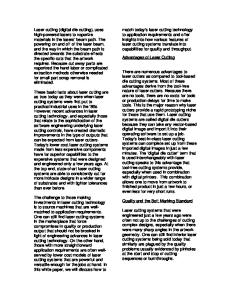
5. The laser power supply is broken, there are two ways, a) The fan on the laser power supply should work after turning on the switch of the supply, otherwise the laser power supply is broken and need to be changed. b) Check the electric wire of the laser power supply. c) The following is the 200W laser power supply sketch map
26
¾
Pin 1 is H (TH) input signal, which controls the optical switch, when the voltage ≥ 3V, the signal will agree the laser tube to send out laser, when the voltage ≤ 0.3V, the signal will not agree the laser tube to send out laser.
¾
Pin 2 is L (TL) input signal, which controls the optical switch, when the voltage ≥ 3V, the signal will agree the laser tube to send out laser, when the voltage ≤ 0.3V, the signal will not agree the laser tube to send out laser.
¾
Pin 3 is P (WP) input signal, which controls the optical switch, when the voltage ≥ 3V, the signal will agree the laser tube to send out laser, when the voltage ≤ 0.3V, the signal will not agree the laser tube to send out laser.
¾
Pin 4 is G signal. This pin connects the machine body and control card.
¾
Pin 5 is the IN input signal controls the laser power. It can be controlled by 0-5V analogue signal or 5V PWM signal.
¾
Pin 1 is 5V VOUT. The maximum current output is 20mA.
If connect one resistor between pin 5 and pin 6,
could enlarge the electricity and increase the laser tube power; ¾
Pin 7 is the ground wire of the laser power supply;
¾
Pin 8 is the negative electrode of the laser power supply
¾
Pin 9 is the positive pole of the laser power supply;
First, check if any signal from the PMC6535; when ray continuously, please test the high-level voltage input signal pin 1 and control signal pin 3 by multimeter ( put the positive pole into the high-level voltage input signal pin 1, negative electrode put on the ground wire pin 4), to see the voltage in the multimeter. If the voltage is much less than 3V, then no signal provided from the MPC6535 board; If no problem as above, test the water-cooling protect wire, short circuit the pin 3 and pin 4, to see if output while opening the laser ( Do open the water chiller to cooling the laser tube when open the laser, or else will damage the laser tube); if ray, it means there is something wrong with the signal in water chiller; check the water-cooling protect wire if poor connected;
27
If no problem as above, check the socket of the digital line if connected well; The pin definition of
power wire (normal use for laser tube more than 100W)
¾
Pin 1 is 5V VOUT. The maximum current output is 20mA.
¾
Pin 2 is H (TH) input signal, which controls the optical switch, when the voltage ≥ 3V, the signal will agree the laser tube to send out laser, when the voltage ≤ 0.3V, the signal will not agree the laser tube to send out laser.
¾
Pin 3 is L (TL) input signal, which controls the optical switch, when the voltage ≥ 3V, the signal will agree the laser tube to send out laser, when the voltage ≤ 0.3V, the signal will not agree the laser tube to send out laser.
¾
Pin 4 is P (WP) input signal, which controls the optical switch, when the voltage ≥ 3V, the signal will agree the laser tube to send out laser, when the voltage ≤ 0.3V, the signal will not agree the laser tube to send out laser.
¾
Pin 5 is G signal. This pin connects the machine body and control card.
¾
Pin 6 as the IN input signal controls the laser power. It can be controlled by 0-5V analogue signal or 5V PWM signal.
7.2
The laser is very weak.
(1)The laser tube is too old. (2)The focus lens is dirty.
Need to change a new laser tube. Take down and clean the focus lens.
(3)The reflector mirrors are dirty. Take down and clean the reflector mirrors. (4)The laser path is not right. Adjust the laser path and make it vertical with the worktable. (5)The focus distance is wrong. Adjust the focus distance.
28
7.3 The engraving surface is not plain Fault phenomenon: there is apparent spine phenomena while cleaning the bottom; when intaglio processing, there is apparent uneven phenomena In the place of rank crossed, when Yang Eagle processing, there is apparent spine horizontal line between the place has character or no character; the deeper clean, the more apparent phenomena. 1. Failure cause (a)The speed is too fast. Please reduce the processing speed. (b)The flow of the air generated by the air pump is not steady. The powder is cumulate. Regulate the blowing of the gas, to ensure no powder adhesion, side-blowing is better. (c) The laser path or the focus distance is not correct. Adjust the laser path or the focus distance. (d) The focus lens is not suitable. Change the lens into short focal length lens. 2. Regular failure and obviate method (a)First, guarantee the light path is right by checking it (b)Lower the processing speed, increase the frequency of the laser output switch; (c)
Adjust well for the gas well, to ensure no flour adhesion,it’s better by side-blown;
(d)Adopt the short focus Len, consider the processing thickness while adjusting the Focus Len; 7.4 Spots scattered, not focusing, lens cone heat…phenomena of laser engraving machine. 1. Fault phenomena: the laser beam machining can see yellow, and the rough beam diameter, hollow spot, when the hands touch the focusing tube, has a heat feeling. 2. Fault: a) water temperature of laser tube is too high. b) Lens pollution. c) Laser tube holder is unreasonable, which lead to the internal tube deformation. d) Ray path moved to one side, the focusing effect is poor, it is the main cause of focus drum heating and the sparking in the light exit of laser head. e) Lens is choose unreasonable, when adjusting the focus, not consider the depth of processing then caused the poor focusing. f) There is something wrong with the laser tube quality. 3. Exclusion method: a) Ensure that the water temperature in the laser tube is below 32 degrees. b) Adjust the ray path, make sure the ray path is correct and well, and consider the processing depth when adjusting the focus length.
29
c)Ask our clients clean the lens and mirrors on time, make sure that they are not polluted; Choose the focus lens reasonably, and make sure the ray light is well. d) Check the position of laser tube holder, and adjust it to the right position. e) Change another new laser tube. 7.5 Sparking from the exit of laser head 1. Check the air blowing tube of the laser head if there is strong air current shoot up, because the air tube is too long and easy to be bended, blocked or worn out. Solving method: clean or change the white color air blowing tube. 2. Check the air compressor itself if there is something wrong, for example: the air-output is too small; or it doesn’t work. Solving method: change a new air compressor. 7.6 Water chiller alarming 1. Firstly, ensure the power supply system normally. Low voltage is easily caused water chiller alarming. So we must make sure the voltage normal, if necessary, chooses the voltage stabilizer. 2. Check the water quantity in the water chiller, less water could cause alarming. Solving method: fill up pure water. 3. Check the water tube if it is bended or blocked, whether the water protection is blocked. Solving method: clean or straighten the water tube or water protection. 4. Check the water temperature; see if it is much higher than the limited value. Solving method: change the water often, or restart the machine to engrave after half an hour. 5. Check the inner of water chiller and see is there anything wrong with the water outputting, no water or less water. Solving method: Change a new water chiller. 7.7 X axis or Y axis does not move around or move abnormally. 1. Control card loosen or stoppage. 2. Limit switch or data line stoppage, check the limit switch, if it has signal, if the line connected well. 3. Drive of equivalent axis stoppage, check the drive supply electricity or not, signals is normal or not. 4. Servomotor of equivalent axis stoppage, check the connecting line of the motor short circuit or not, if it is abnormal, change a motor please. 5. Check whether the connecting line between motor and driver is loosen or connected well or not. 6. Check whether the couping is broken or loosen. 7. Equivalent screw rod is broken or the screw of the screw rod stoppage. 8. Equivalent axis’s slide rod stoppage. 9. Driver’s subdivision, electric current are different from the software designed.
30
7.8 Laser head or beam shaking. 1. After power off, move the laser head and beam by hand, if there is obvious resistance, please check the left tensioning wheel, lead rail and slide block. Solving method: Clean the lead rail, slide block, changes the tensioning wheel. 2. Check whether the laser head and air blowing tube are locked or not, whether the beam is shift too much or not. Solving method: adjust the beam, straighten the air blowing tube. 3. Push the laser head, check if there is a fricative or shaking. If yes, that is because the space of the slide block is too large, so change another slide block. 4. Check whether the motor and driver is connected well or not. 5. Check the transportation parts of the machine (coupling, shaft block, screw of the screw rod, straight line bearings and slide block), whether they are loosen or broken, reasonable assembling (loose or tight). 6. Start the machine, check which axis shaking, laser head or beam. Cut off the supply of one axis, check the other axis’s motor and driver, if there is stoppage. Interchangeable test, find which axis’ motor or drive the problem is. If there is any stoppage, change another one in time. 7. Reset in the right direction, but in the end, the laser beams can not stop or crash the machine. So we need to check the parameters of motherboard, whether sensor dust is excessive or not, the sensor cable is disconnected or the sensor is damaged. 8. If the problem still exists, may be motherboard failure, contact with the factory replacement motherboard. 7.9 Different engraving depth or could not engrave deep depth 1. Check whether the water circulation system is smoothly flowing (water pipes bent or broken); 2. Check whether the focal length is normal, if the focal length is wrong, please adjust the focus. 3. Check whether the laser path is right, if so, please adjust the laser path again. 4. Check whether the mirrors or lens are dirty, if so, please clean them. 5. Check whether the lenses are broken, if so, please change new one. 6. Check whether the outside of the laser tube is dirty, if so, please clean it. 7. Check whether the worktable is plain. 8. Check whether the X-axis cross girder is parallel. 9. Check whether the temperature is higher than 30℃ (change the water for cycling) 10 Check whether the laser head or Focus Len is loose (fasten them) 11. Check whether the laser tube is aging (change it; free changing within guarantee time)
31
7.10 Wrong engraving and not following the file engraving 1. Initialization is not correct, the data was sent out (please make a change) 2. Operation was not in order(need to key in again) 3. Control card problem 4. The configuration number of the software was problem 5. The driver fault or current subdivision numbers setting was different with the software. 6. Inverter interference or wire problem. 7. Electrostatic interference 7.11 Wrong size or not closing and malposition when its engraving 1. Edited files is it correct (reset again) 2. Select filed is it out from the size of the layout (choose again) 3. Please check with the parameter of software is it right(set again) 4. To the belt left and right, check if the tightness degree are consistent. If the synchronous belt is too loose, the performance will appear double image for engraving letter; if too tight, will damaged to the synchronous belt. Please adjust the synchronous belt if there is something wrong with it: adjust the screw to suitable degree, no double image for engraving letter and low noise while running the machine. 5. Check the belt or synchronous belt is slip or Jumping over Teeth ( fasten the synchronous wheel or belt) 6. Please check the beam is it parallel. 7. Please check the pulley at the laser head is it abrade, that's made the laser head not hard up, that must need to change a new pulley. 8. Please check the computer system is it right (please installation the software again) 7.12 No output from the computer Please check with the parameter of software running is it correctly(reset again)
1.
When the laser machine was running ,is it fixed position as first or not ,after that can output the
data(reset the output) 1. Please check is it not datum when its starting the job(reset again) 2. Please check the output gorge is it same as software setting.(reset again) 3. Please check the earth line is it stable, and the static electricity is it interference the wire(make the earth connection again) 4. Change the gorge and texting the output 32
5. Please installation again for the laser software and texting again 6. Please formatting the computer system and installation the software again and texting again. 7. Please check the main board gorge is it damage ,if its please repair or change a new one . 7.13 SOFTWARE ERROR ALERT INTERFACE. The operation panel can real-time display the alert interface ,which cause by various improper operation or external disturbance signal. According to the information which display on the panel , it is easy for the user to correct the wrong operation, and exclude the external disturbance signal . 1. Soft limit stops When found this kind of error , it show that the work scope data ,which input into the computer is bigger than the real worktable . Solution : Remove the laser head, and make it in the scope of the worktable. Another way is that conceal the “immediately output order “reset the proper data again, and then download the data . 2. Hard limit stops When the user operate the machine while does not make the laser head back to the original point .It is easy cause that the processing area is bigger than the real worktable and when the laser head bump into the “size control signal “ the movement have to cease . On the other hand, when the machine in a complex environment which have a lot of interference signal , it will also display this kind of information . Solution : Remove the laser head ,and make the processing graphic data in the scope of the worktable. When we find the alert information while the laser head does not bump into the “size control signal “ so we can sure ,it is caused by the external disturbance signal . When we meet this kind of situation, please check the ground cable 3. Lack of memory space alarming Reasons: a)The number of download files is more than the total number of
Memory device—32
b) The download files is too big and exceed the Memory device Solving Method: Make sure that the download files not exceed the total memory of Memory device. Remove the files that we don’t
33
need, release the memory space. 4. Configuration and firmware mismatching Reasons: After firmware updating, not download the configuration and file to match with this firmware. Solving method: a) Open the installation catalogue of application procedure, operate version testing procedure, check if the function library match with firmware version, if not match, please contact with the supplier to get a matching function library. b) Double-click application procedure, download configuration. 5. The error of function baseband firm ware mismatching Reason for this error: The function base for making processing file mismatch with firm ware. Solving method: The version number of controller for movement is not visible for change, unless to upgrade this controller via “firm ware loading”. 6. Hardware and firm ware mismatching Reason for this error: After upgrading of the firm ware, hard ware doesn’t support the new one. Solving method: a)
Please copy the new firmware file (FM.FMW and 05LM201.HDW two files) to the root directory of U-disk
(formatted as FAT16, we propose that U disk do not have any other files) b) Break off the power of MPC6515/35, insert U disk and then connect power for MPC6515/35, the light D1 on MPC6515/CPU main board flash 2 times fast and D1 is always on (usually 2 to 5 seconds, depending on the firmware), firmware is being updated at this time; if U disk with lights, following the instructions of U disk to observe whether it is reading data via the flashing light, 6535 plate could be judged by observing light on U disk; c) D1 on MPC6515 main board flashing quickly, indicating the updating of the firmware finished ; if U disk with lights, follow the instructions to observe whether the reading of the data finished via flashing lights, It is about 15 seconds; d) Extract U-disk, MPC6515/35 will normally start DSP firmware program. If MPC6535 can not work normally when U-disk extracted, maybe a firmware need to be updated. So repeat the steps to update the firmware. If MPC6515/35 still can not work normally, contact distributor.
34
7.14 Normal problems of software 1. When engraving with gradient, double phenomenon This phenomenon occurs when the slope of words carved smaller, usually the reason is "wide" setting slope too large, cause calculation errors, please set "wide" little slope. 2. If you only can move a graphic with one direction, please click “Shift” or ”Ctrl” to recover. 3. PLT format cannot to engrave There are two reasons, one is the graphic is not closed, the other is graphic double. Please detect this phenomenon with “data detect” tools 4. The size is not same with engraving/cutting samples. Open the item” laser machine set”, adjust the pulse 5. The edge is irregularity when engraving The edge is irregularity maybe happen when you use the DSP5.3 engraver software, that means “burr”, this is mainly caused by mechanical return clearance, this is the solution a) Draw a box (rectangular or square), set work mode for the laser carving, the sculpture is 0.5 mm instead, then see engraving effect, theoretically, should be aligned, namely the odd interlaces did edge should be aligned, even did edge also should be aligned, only the odd and even did not have a little. b) When you open” set engraving parameters”, the parameters for different engraving speed can be seen, the reverse gap is”0”,you should adjust it as the matter of fact. c) You can chose” single-track light” when best engraving effect needed. Not to chose the draw of “dual-engrave”, but when you chose it, the efficiency would be lower. 6. The X-axis or the Y-axis not move(MPC6535) a)
Stir knob to chose the DC 5V, test the voltage between PULX(or PULY)and GND. Take Y axis as example,
click the button of ‘up’ or ‘down’, the normal voltage is 2.8V, if it is not, we could confirm the controller was broken, please change the controller. If it is, please go to next step. b)
Exchange the output terminal of the two drivers, then press “ Up” or “Down” button; if X axis works normal, it
means there is something wrong with the motor on Y axis, please change a new one; if X axis doesn’t work, it means there is something wrong with the driver on Y axis, please chance it; 7. X Axis and Y Axis work in only one direction; a) Test the voltage between the DIRX and GND after pressed the
multimeter into grade 5V; take the X Axis for
example, press “ left”, then press “ right” to see if there is some change on high level (>2.8V) and the low level(2.8V) and the low level(