International Journal of Emerging Technology and Advanced Engineering Website: www.ijetae.com (ISSN 2250-2459, Volume 2, Issue 5, May 2012)
Module Based Implementation of Partial Reconfiguration for Multipliers Sameer Ashtekar1, Prof. V.A. Tehare2 1
Research Scholar, Electronics &Telecommunication Engineering, G.H.Raisoni College of Engineering, Nagpur, India Asst. Professor, Electronics &Telecommunication Engineering G.H.Raisoni College of Engineering, Nagpur, India
2
[email protected],
[email protected]
In particular, two important benefits can be achieved by exploiting partial dynamic reconfiguration on reconfigurable hardware: (i) the reconfigurable area can be exploited more efficiently with respect to a static design; (ii) some portion of the application must change over time and react to changes in its environment. The two main advantages given by a Partial Dynamic Reconfigurable (PDR) solution thus address the lack of resources needed to implement an application and its adaptability needs.Reconfigurable hardware taking advantage of partial dynamic reconfiguration can be thus seen as the middle point in the trade- off between the speed of HW solutions and the flexibility of SW [2]. An 8- bit reconfigurable computational element can execute one 8-bit & two 4-bit computations depending upon partitioning signals. Based on fast addition algorithms, a number of Reconfigurable adders and array multipliers have been proposed . It should be mentioned that an configurable multiplier blocks was developed for embedding in FPGAs [4, 5]. Each block is a 4 x 4 array multip1ier: An array of these blocks is capable of being configured to perform4m bit x 4n bit signed unsigned binary multiplication. Since each block is a 4 x 4 array multiplier, it inherent has ripple carry adder. In addition, additional gates are needed to achieve the configurations and additional control signals are also needed. In other words, the programmability is achieved at the cost of higher gate count and more delay degradation [6, 7].In this approach, a larger multiplier is cascaded from smaller blocks, while our approach goes the other way around, i.e., a larger multiplier is partitioned into a number of smaller multiplier. Therefore, the developed approach offers three salient features: (a) low area overhead; (b) virtually no performance degradation; and (c) low power dissipation for executing smaller multipliers. In the next section, module based partial reconfiguration is discussed. Section 3 presents basics of array multiplier. Implementation strategy is presented in section 4. Section 5 gives the conclusion of the concept and work.
Abstract- Reconfigurable computing play a vital role in this modern world of computer and electronics engineering,it allows to execute different application on the same hardware.Partial reconfiguration dynamically modify hardware portion of the device just by downloading configuration bit files.This results in increase in speed and functionality of FPGA based system.This paper presents flow of partial reconfiguration and implementation of reconfigurable modules using Planahead software on Xilinx virtex-5(XC5VLX50).Planahead software specifically design for partial reconfiguration as it has advance floorplanning capabilities.In order to verify the functionality, reconfigurable modules are designed and simulated using simulation tool on Xilinx 13.1 (ISE). Keywords- FPGA,ReconfigurableModules,Partial reconfiguration, Multipliers,virtex-5(XC5VLX50),Planahead Software.
I. INTRODUCTION Field programmable gate arrays (FPGAs) are quickly becoming the usual targeted technology for many development efforts.FPGAs are programmable logic devices which allows the implementation of digital systems. They provide an array of logic cells that can be configured to perform a given functionality by means of a configuration bit stream. Many of FPGA systems can only be statically configured. Static reconfiguration means to completely configure the device before system execution. If a new reconfiguration is required,then it is necessary to stop system execution and reconfigure the device it over again. Some FPGAs allow performing partial reconfiguration, where a reduced bit stream reconfigures only a given subset of internal components. Dynamic Partial Reconfiguration (DPR) allows the part of device be modified while the rest of the device (or system) continues to operate and unaffected by the reprogramming [1].
437
International Journal of Emerging Technology and Advanced Engineering Website: www.ijetae.com (ISSN 2250-2459, Volume 2, Issue 5, May 2012) II. MODULE BASED PARTIAL RECONFIGURATION
III. ARRAY MULTIPLIER
A. Modular Design
1-bit x 1-bit is an AND gate. Look at the partial product matrix and just add it up using full-adders. The partial product in the first row is added to that in the second row, and so on.Following is the multiplication and partial product matrix for two 4 bit numbers X and Y.
The modular design flow allows the designer to split the whole system into modules. For each module, the designer generates a configuration bit stream starting from an HDL description and going through the synthesis, mapping, placement, and routing procedures, independently of other modules [8]. The modular design flow consists of „Modular Design Entry / Synthesis‟ and „Modular Design Implementation‟. „Modular Design Entry and Synthesis‟ step must be done for top-level design and the modules. Top-level design is designed by team leader and consists of „black box‟ for each sub-modules and „wiring‟ for interconnection of each sub-modules. „Modular Design Implementation‟ step comprises following three phases. 1) Initial budget phase: In this phase, the team leader assigns top-level constraints to the top-level design. Top-level constraint needs to area constraint and bus macro assignment. 2) Active module implementation: In this phase, the team members implement the reconfigurable modules. 3) Final assembly: In the phase, the team leader assembles and implements the top-level design using each submodule and generates top-module bit stream [9].
x3
x
y3
x2
x1
x0
y2 y1
y0
z30 z20 z10 z00 z31 z21 z11 z01 z32 z22 z12 z02 z33 z23 z13 z03 P7 P6 P5 P4 P3 P2 P1 P0 zij = xi yj
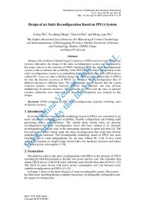
B. Module-Based Partial Reconfiguration Module-based partial reconfiguration method is a special case of modular design [9]. And this method can reconfigure only a given subset of internal components during device is activating. A complete initial bit stream must be generated, and then, partial bit steams generated for each reconfigurable module. Hardwired Bus Macros must be included in design as shown in Fig. 1. These macros guarantee that each time partial reconfiguration is performed routing channels between modules remain unchanged, avoiding contentions inside the FPGA and keeping correct intermodule connections [7, 8].
Figure 2: 4x4 Array Multiplier
Figure 1: Hardwired Bus Macros
Figure3:simulation result of 4x4 multiplier using Xilinx ISE 9.1i
438
International Journal of Emerging Technology and Advanced Engineering Website: www.ijetae.com (ISSN 2250-2459, Volume 2, Issue 5, May 2012) B. Generalities The regular synthesis flow generates a single bitstream for programming the FPGA. This considers the device as a single atomic entity. In contrast, the PR flow physically divides the device in regions. One region is called the “static region”,which is the portion of the device that is programmed at startup and never changes. One region is the “dynamic region” or “the PR region”, which is the portion of the device that will be reconfigured dynamically, potentially multiple times and withdifferent designs.It is possible to have multiple PR regions .The PR flow generates at least two bitstreams, one for the static and one for the PR region.Most likely, there will be multiple PR bitstreams, one for each design that can be dynamically loaded. The user circuits instead go into the PR region. Another practical example is an FPGA board where we can also place the PCIe interface logic in a static region of the FPGA and the user circuits in the PR region. The PR region is a physical entity, with a given geometry. PlanAhead is the tool that allows you to define the exact location of the PR region on your target device.
Figure4:simulation result of 8x8 multiplier using Xilinx ISE 9.1i
IV. PARTIAL RECONFIGURATION DESIGN CRITERIA FOR XILINX ISE 13.1
V. IMPLEMENTATION PlanAhead: The Xilinx partial reconfiguration design flow is managed by the PlanAhead application included in the Xilinx IDE. This is the tool that allows you to define the physical placement of the static and PR regions on your target FPGA. The netlists generated using synthesis tool ISE (13.1) in the previous sections must be imported into a PlanAhead project and used to implement the design for the targeted FPGA[11].
Partial Reconfiguration (PR) is an expert flow within the ISE® Design Suite. A.Design Requirements • PR requires the use of ISE 12.1 or newer. • Device support: Virtex®-4, Virtex-5, Virtex-6 • All variants of these devices are supported. • PR is supported via the PlanAhead™ software or command line only; there is no Project Navigator support. • Floorplanning is required to define reconfigurable regions. • Bottom-up synthesis (to create multiple netlist files) and management of reconfigurable module netlist files is the responsibility of the user. • Synthesis done outside of PlanAhead - any synthesis tool may be used. • Decoupling Logic is highly recommended to disconnect the reconfigurable region from the static portion of the design during the act of Partial Reconfiguration. • Standard timing constraints are supported, and additional timing budgeting capabilities are available if needed. • A unique set of Design Rule Checks (DRCs) has been established to guide users on a successful path to design completion. • A PR design must consider the initiation of Partial Reconfiguration as well as the delivery of partial BIT files, either within the FPGA or as part of the system design[10]
A. Implementation flow Step1 : start with the HDL description of the design. 11: Synthesize the static part and reconfigurable modules using xilinx 13.1(ISE) synthesize tool Step2: placing and routing (PAR) and mapping. Step 3: creating a planahead project. (a) specify synthesized (EDIF or NGC) netlist.(b) Set PR project Step4: Set the location of the static netlists. (a)specify the top netlist file.(b) specify the UCF file. Step5: select the targeting device i.e virtex5,family XC5VLX50. B. Floor planning Partial Reconfigurable Partition: Step1: create netlist design Step2: set the partition ,(a)set the partition is reconfigurable (b) add reconfigurable module as black box without netlist. Step3: assign pblock mode,draw a rectangle on FPGA die.
439
International Journal of Emerging Technology and Advanced Engineering Website: www.ijetae.com (ISSN 2250-2459, Volume 2, Issue 5, May 2012) C. Adding Reconfigurable Instances to the Partial Reconfiguration Partition: Step1: Add 4x4 multiplier as a reconfigurable module. Step2: Again add 8x8 multiplier as a reconfigurable module. Create Design Instances for Implementation: Step1: In the Design Run window, click on Create New Run. D. Implement Designs: Step1: Right-click „config_1‟ in the „Design Runs‟ pane and select „Make Active‟. Step2:Right-click „config_1‟ and select „Launch Runs‟. Step3: When the implementation completes, select Promote Partitions.
Figure7:bitstream generation successifully completed
E. GENERATING BITSTREAM Step1:Right-click„config_1‟and select „Generate Bitstreams‟. Step2:Repeat step 1 for each configuration. IMPLEMENTATION RESULT[11]: Bitstream name Config_1.bit
Figure5: Implementation Completed
Step4: Repeat above steps 1 through 3 for each Design Run Configuration i.e config_2 and config_3 [11,12].
Full Bitstream
Config_1_multi_1_bl ack_box_partial.bit
Partial Bitstream
Config_2.bit
Full Bitstream Partial Bitstream
Config_1_multi_1_fo ur_bit1_partial.bit
Contents Static portion & black box user module. Black box user module(blanking bit stream) Static portion & original user module Original user module
Config_2.bit
Full Bitstream
Static portion & alternate user module
Config_1_multi_1_ei ght1_8_partial.bit
Partial Bitstream
Alternate user module
V. CONCLUSION We have presented a Reconfigurable Multiplier Array organization. Thus we have generated bit files for reconfigurable modules i.e for 4x4 multiplier and 8x8 multiplier through planahead implementation tool.The proposed unit can be implemented on a VLSI intended to be used as a run time configurable unit, and it can also be used in reconfigurable technology as run time reconfigurable unit.
Figure6:Floorplanning with design run.
440
International Journal of Emerging Technology and Advanced Engineering Website: www.ijetae.com (ISSN 2250-2459, Volume 2, Issue 5, May 2012) This propose unit increase the speed and functionality of FPGA. The whole array is configured using multiplexors, which can be replaced with faster connections on a partially reconfigurable environment. Several units are been coded and synthesized to have a wide comparison environment, furthermore, a brief analysis of the obtained results in terms of area used and time delay are presented given a maximum work frequency of 50 MHz for the calculus for a 4x4 macroblock. References [1]
A. D. Booth. A Signed Binary Multiplication Technique. Quarterly Journal of Mechanics and Applied Mathematics, 4(2):236–240,June 1951
[2]
L. Dadda. Some Schemes for Parallel Multipliers. Alta Frequenza, 1965.
[3]
Nan Y S, Chen O T.Low-power multipliers by minimizing switching activities of partial products. IEEE International Symposium on Circuits and Systems[C]. Arizona,USA. IEEE Circuits and Systems Society ,2002.
[4]
H. Eriksson, P. Larsson-Edefors, M. Sheeran, M. Själander, D. Johansson, and M. Schölin, “ Multiplier reduction tree with logarithmic logic depth and regular connectivity,” in Proc. IEEE Int. Symp. Circuits Syst. (ISCAS), May 2006, pp. 4–8
[5]
whitney J.Townsend EarlE. Swartzlander, jocob A.Abraham “A Comparison of Dadda and Wallace multiplier delays”.
[6]
Magnus Sjalander, Per Larsson Edefors, Multiplication Acceleration Through Twin Precision. IEEE Trans. VLSI., vol. 17, pp.1233–1246, Sep. 2009.
[7]
C. R. Baugh and B. A. Wooley, “ A two‟s complement parallel array multiplication algorithm, ” IEEE Trans. Comput., vol. 22, pp. 1045–1047, Dec. 1973
[8]
Two Flow for Partial Reconfiguration: Module Based or Difference Based, Xilinx website[online] http://www.xilinx.com/support/documentation/application notes/xapp290.pdf,
[9]
M.Själander, H.Eriksson, and P.Larsson-Edefors, “An efficient twin precision multiplier,” in Proc. 22nd IEEE Int. Conf. Comput. Des., Oct. 2004, pp. 30–33.
[10]
Partial Reconfihuration User Guide, UG702 (v13.1), march 1, 2011.
[11] Richard Neil Pittman,Microsoft Research February 2012, Technical Report ,MSR-TR 2012-19. [12]
Solomon Raju Kota, Ashutosh Gupta, Shashikant Nayar, and Sreekanth Varma.” Module Based Implementation of Partial Reconfiguration Using VHDL on Xilinx PFGA” International Jour nal of Recent Trends in Engineering, vol 2,No.7,November 2009.
441