02/20/2014
2013 Chassis Cab Exterior Lighting Modifications / LED Rear Lighting
Modifying the exterior lighting of the Ram truck The Ram truck has been designed and developed using standard incandescent lights. These lights are controlled by a computerized module called the “Central Body Controller” (CBC). This module controls the left front, right front, left rear and right rear lighting independently. The CBC utilizes “smart” technology that has the ability to monitor the current (amperage) on some of the lighting outputs. These monitored outputs include the headlamps, turn lamps, stop lamps and reverse lamps. The module is able to detect both electrical short and open circuit conditions. The module has a preset allowable current (amperage) operating range for each of these outputs. If while in normal operation the current detected falls outside this preset range, then a fault is set in the module. In the case of too high of current the circuit will be shut off. This fault condition will remain true until the current level falls back into the normal range. In the case of the turn lamp circuits, if the module detects too low of current then the module will assume an open circuit condition (burned out bulb) and the blinker will flash at a double flash rate. This detection is in place to assist the customer in determining if there is an active short in the lighting circuit or a burned out bulb (open circuit). You can also get into these fault conditions by adding additional lamps to the circuits or by changing the lamp specifications (i.e. changing the type of lamp used). This would include, but is not limited to, the use of LED’s. By using them you run the risk of causing lighting faults or loss of lighting functionality. The question then becomes, “can you use LED lighting on Ram trucks”? The answer is yes, but special care and procedures need to be followed to use LEDs successfully.
Use of LED lamps in conjunction with the original equipment incandescent lamps: If you are keeping the original incandescent lamps (or the aftermarket equivalent) and you want to add additional LED lamps for use as stop, turn, reverse or park lamp function you can do so with no additional changes to the vehicle or its electrical system.
Adding additional incandescent lamps to the original equipment incandescent lamps: Customers sometimes desire to add additional lamps to the exterior lighting circuits. This is possible but requires adding a relay to control the additional lamps. By correctly wiring the relay into the lighting circuit you only add the additional coil resistance of the relay. This will maintain the correct operating current (amp) range of the circuits and no faults will be set. A relay will need to be added to each side of the vehicle (left and right). Below is a sample relay circuit which can be utilized to add additional lamps
1
02/20/2014
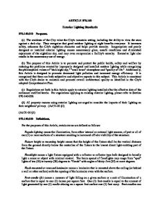
2013 Chassis Cab Exterior Lighting Modifications / LED Rear Lighting Below is a sample relay circuit which can be utilized to add additional lamps
Battery positive Added Relay
New Lamp
fuse
coil
connect to existing vehicle lighting circuit
When this type of circuit is used please understand that there is no way for the vehicle to perform any diagnostics on the added lamps. As a general statement the CBC does not provide a large enough current range on the head, turn, stop or reverse lamp circuits to add any additional incandescent lamp loads. It is therefore strongly recommended that the above procedures are followed for modifying the exterior lighting.
Replacing rear incandescent bulbs with LED’s: For 2013 there are three different methods to eliminate fast flash and error codes when replacing rear stop/turn incandescent bulbs with LED’s – NOTE: You must complete these modifications BEFORE the error codes are created. If you have error codes you must unground the circuit, reinstall incandescent bulbs and turn on the turn signals to eliminate the faults. Then reground the circuit. Method (A) Cut the appropriate harness wire at the CBC, add wire length, add a ring terminal, and ground this circuit at an appropriate location. Method (B) Add the wire/terminal kit (part number P68225777AA) provided with the vehicle. Method (C) Add power resistors to the rear light circuits.
2
02/20/2014
2013 Chassis Cab Exterior Lighting Modifications / LED Rear Lighting Detailed instructions for each of the three different methods are delineated below: Method (A) – cut and adds wire to a circuit at the CBC, refer to photos below. Method (B) – use wire/terminal kit (part number P68225777AA) provided with the vehicle, refer to photos below. Method (C) – add power resistors to the rear light circuits. This is the same procedure that could be employed from previous model years. Wire a 9 or 10 ohm, 50 watt power resistor in parallel with each LED. The resistors must be capable of surviving exterior exposure on the vehicle with consideration for vibration and expected life cycle. As power resistors may get hot under normal operation it is suggested that they be placed in an area with adequate ventilation and heat dissipation. It is further suggested that they be located very near the LED’s; this is to help with any future service related maintenance or repairs to the lighting circuits.
Method (A) :
CBC module location under dash
3
02/20/2014
2013 Chassis Cab Exterior Lighting Modifications / LED Rear Lighting
Method (A) : Connector to be modified
To remove connector from the CBC, push in tab while simultaneously lifting bail
4
02/20/2014
2013 Chassis Cab Exterior Lighting Modifications / LED Rear Lighting
Method (A) : Connector removed from the CBC
Circuit L563 cut and insulation stripped from the connector side of the cut circuit. L563 is a WT/GY wire in cavity #27.
5
02/20/2014
2013 Chassis Cab Exterior Lighting Modifications / LED Rear Lighting
Method (A) : Circuit L563 cut and insulation stripped from the connector side of the cut circuit. L563 is a WT/GY wire in cavity #27.
Additional wire and a ring terminal soldered onto the connector side cut circuit, ground the ring terminal at an appropriate location
6
02/20/2014
2013 Chassis Cab Exterior Lighting Modifications / LED Rear Lighting
Method (A) :
If the vehicle is equipped with a premium radio and auxiliary amplifier, the amplifier will need to be temporarily removed to gain access to the CBC connector
7
02/20/2014
2013 Chassis Cab Exterior Lighting Modifications / LED Rear Lighting
Method (A) : If the vehicle is equipped with a premium radio and auxiliary amplifier, the amplifier will need to be temporarily removed to gain access to the CBC connector
8
02/20/2014
2013 Chassis Cab Exterior Lighting Modifications / LED Rear Lighting
Method (B) :
Connector located behind the left (driver’s side) front wheel well liner
Connector from underneath
9
02/20/2014
2013 Chassis Cab Exterior Lighting Modifications / LED Rear Lighting
Method (B) :
Push in tab while simultaneously lifting bail to unlock the two connector halves
Connector from underneath
Using a prying tool pull the connectors “X-mas” tree clip out from its mounting hole and pull the two halves of the connector assembly apart
10
02/20/2014
2013 Chassis Cab Exterior Lighting Modifications / LED Rear Lighting
Method (B) : Using a small flat blade screw driver carefully “work” the white plastic terminal lock partially out of its lock position
Carefully fully remove the white plastic terminal lock, note the “clocking” of the lock to aid in correct re-installation
11
02/20/2014
2013 Chassis Cab Exterior Lighting Modifications / LED Rear Lighting
Method (B) : Carefully fully remove the white plastic terminal lock
Backside of connector (difficult to see on vehicle), this orange plug is to be pushed out and discarded
12
02/20/2014
2013 Chassis Cab Exterior Lighting Modifications / LED Rear Lighting
Example of a thin pick tool
Cavity #15 has the orange color plug in the reverse side
13
02/20/2014
2013 Chassis Cab Exterior Lighting Modifications / LED Rear Lighting
Method (B) : Using a thin pick tool, carefully push tool (painted orange in this photo for clarity purposes) into cavity #15 to push orange plug out of cavity.
Wire harness kit provided with the vehicle
14
02/20/2014
2013 Chassis Cab Exterior Lighting Modifications / LED Rear Lighting
Method (B) : Close-up of kit terminal, note direction of upstanding metal “tab” on metal terminal
Wire harness kit ready for insertion into now empty connector cavity #15 note direction of upstanding metal “tab” on metal terminal
15
02/20/2014
2013 Chassis Cab Exterior Lighting Modifications / LED Rear Lighting
Method (B) : Wire harness kit partially inserted into connector cavity
Wire harness kit fully seated into connector cavity
16
02/20/2014
2013 Chassis Cab Exterior Lighting Modifications / LED Rear Lighting
Method (B) : Wire harness kit fully seated into connector cavity
Add additional wire as necessary to reach the grounding location of your choosing, add a ring terminal and securely fasten to ground location Align the white plastic terminal lock noting the same “clocking” as before removal
17
02/20/2014
2013 Chassis Cab Exterior Lighting Modifications / LED Rear Lighting
Method (B) : Carefully push the lock to fully seated position
Reassemble the two halves of the connector assembly, lock the bail into place, and reinsert the X-mas tree clip into its mounting hole
18