Modeling of Harmonic Sources Magnetic Core Saturation Yilu Liu and Zhenyuan Wang Department of Electrical Engineering, Virginia Tech Blacksburg, VA 24061-0111, USA
[email protected]
2.3.1 Summary This section introduces the modeling of harmonic sources due to magnetic core saturation and several case studies. Different transformer models have been developed in the past for steady state and transient analysis of power systems. Some of these models have nonlinear components to take into account the magnetic core saturation characteristics so that harmonic generation can be simulated. Case studies based on these models are presented to demonstrate the harmonic generation behaviors of transformers under different saturation conditions.
2.3.2 Introduction Magnetic core saturation of power transformers and rotating machines can generate harmonics. Fig. 1 illustrates the principle of harmonics generation from magnetic core saturation[1]. In order to maintain a sinusoidal voltage, sinusoidal flux must be produced by the magnetizing current. When the amplitude of the voltage (or flux) is large enough to enter the nonlinear region of the B-H curve, the magnetizing current needed will be greatly distorted from sinusoidal, and contain harmonics.
condition[2] but can considerably increase their harmonic contribution under abnormal conditions when their magnetic cores are saturated.
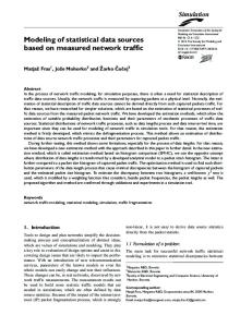
2.3.3 Examples of magnetic core saturation There are many situations which contribute to magnetic core saturation. The following are some common examples. Normal excitation Even under normal excitation condition, transformer core may have entered, slightly, the saturation region and begin to generate some harmonics in the excitation current. The degree of the saturation depends on the transformer design. Overexcitation Overexcitation is basically caused by overvoltage. This problem is particularly onerous in the case of transformers connected to large rectifier plant following load rejection[2]. As in Fig. 2, overvoltage drives the peak operation point of the transformer excitation characteristics up to saturation region so that more harmonics are generated. In this case, the magnetizing current of overexcitation is often symmetrical.
B/ λ / v
Operation point moving into nonlinear region
Overvoltage resulted operation point Normal operation point
H/ i
Fig. 2 Principle of overexcitation resulted transformer saturation Converter load Fig. 1 Principle of harmonic generation from magnetic core saturation Before converter loads were widely used, one of the principal harmonic sources in the power system was the excitation current of power transformers. Although modern transformers do not generate significant harmonics under normal steady state operating
Converter loads may draw DC and low frequency currents from supplying transformers. The transformer cores are biased by these load currents and driven to saturation. For example, a cycloconverter with single phase load as in Fig. 3 will draw DC currents from source transformer when its output frequency fo and input frequency fi have the relationship of f i = 2 nfo , here n is an integer[3].
f
f
i
Three phase transformer
current flowing into terminal i, Rij and Lij (i=1,N; j=1,N) denote the resistance and inductance between terminals i and j, respectively[14]. This model is the framework of transformer models in the electromagnetic transient programs.
fo
i
Cycloconverter
Load
Fig. 3 A cycloconverter with single phase load
A simple Tee model
Geomagnetically Induced Currents (GIC) Geomagnetically Induced Currents (GIC) flow on the earth surface due to Geomagnetic Disturbance (GMD). They are typically 0.001 to 0.1 Hz and could reach peak values as high as 200A. As in Fig. 4, they can enter transformer windings by way of grounded wye connections and bias the transformer cores to cause half cycle saturation[4~10].
Shown in Fig. 5 is an equivalent circuit model of a single phase transformer. It can be used for teaching concepts, simple phenomena investigation and demonstration, simulation of single phase or three phase transformer banks. The Rm can be represented by a piecewise linear vi curve[16,19], or a constant value resistance[18,21,22]. The Lm is often modeled by a two-slope linear inductance[14,16] when the saturation B-H curve has a sharply defined knee which is usually the case of grain-oriented steel cores[15], or more precisely by a multi-slope piecewise curve[15,17,21~23]. The characteristics of Rm and Lm are usually found from no-load test[23]. Ip
Rp
Lp
Ls
+
Rs
Is +
Iex +
Vin
Fig. 4 GIC entering the transformer windings
2.3.4 Modeling of magnetic core saturation A large amount of work has been documented in the literature on modeling of transformer core nonlinearity. Being the predominant factor of power transformer nonlinearity, magnetizing saturation is the major issue over hysteresis and eddy currents. Hysteresis modeling is important in transient studies such as switching or fault condition simulation of transformers[11~13], and is often neglected in harmonic analysis[14~17]. There are different approaches for transformer modeling and solutions: the matrix models[12~16] use an impedance or admittance formulation relating terminal voltages and currents; the equivalent circuitry models[11,17~19] often use simplified Tee circuit whose elements values are derived from test data; the duality based models[20~22] account for core topology and the connection between electric and magnetic circuits. Although the latter two types of models can also be presented in matrix format, they are easier to understand from a circuit point. Due to space limit, only a few model examples will be discussed in this paper. A matrix model One of the matrix models is written as: v1 R11 v 2 = R 21 M M v N R N1
R12 R 22 M R N2
R1N i1 L11 L R 2 N i 2 L21 + O M M M L R NN i N LN1 L
-
Vm
Lm
Rm
-
Im
Vout
-
Rp, Lp: primary winding resistance and leakage inductance. Rs, Ls: secondary winding resistance and leakage inductance. Rm: core losses (hysteresis loss and eddy current loss). Lm: nonlinear excitation inductance.
Fig. 5 A simple Tee model for single phase transformers Duality based models Duality based models are often used to represent three phase transformers[20~22]. This may be due to the fact that the complex core topology of three phase transformers can not be represented sufficiently by an equivalent circuit model or conveniently by a matrix model. Here nonlinear inductances are used to model core saturation[21~22] and the modeling circuits are derived based on the principle of duality between magnetic and electric circuits. Fig. 6 shows four types of duality based three phase transformer modeling circuits. They can be connected as Wye/Wye (Y/Y), Delta/Wye (D/Y), Wye/Zigzag (Y/Z), Delta/Zigzag (D/Z), respectively. The models can be used for harmonic analysis and low frequency transient study. GIC saturation models
L12 L22 M LN 2
L1N L L2 N d O M dt L LNN L
i1 i2 M i N
here N is the number of transformer terminals, vi (i=1,N) denotes the voltage of terminal i, ii (i=1,N) denotes the
For a transformer under severe GIC bias which causes heavy half cycle saturation, it becomes necessary to account for the flux paths in and between core, tank and air gaps. A detailed model based on 3D finite element calculation may be necessary[9]. Shown in Fig. 7 is the equivalent magnetic circuit model of a single phase shell
type transformer. The model can be used for harmonic behavior study of a balanced three phase shell type transformer bank under GIC bias. The model circuit has four branches:
nonlinear time domain circuit and the frequency dependent linear circuit iteratively[24].
Branch 1: Represents the sum of core and air flux all within the excitation windings. The total flux is the sum of both DC(GIC) and AC flux. Branch 2: Represents the flux path in the yoke segment. Branch 3: Represents the sum of flux entering the side leg. Part of this flux will leave the side leg and enter the tank. Branch 4: Represents the flux leaving the core from the center leg. Part of this flux loops back in the air and the rest through the air gaps and the tank.
Cases #1 to #3 are based on the system shown in Fig. 8. The transformer can be either a Y/Y, or a D/Y, Y/Z, D/Z connection. DC bias (if any) are injected into secondary windings by current sources Idca, Idcb and Idcc. Primary winding currents are Iwa, Iwb and Iwc. Power system line currents are Isa, Isb and Isc.
2.3.5 Case studies
Transformer
Idca
X
Power system
A
X
L hx
Lo
L xy
Lm
Primary Idcb
Ga
A
Ga
Gc
Lo
L hx
Resistive load
Secondary
Lm Ga
a
Gc
Idcc
Y
a
Y
B L hx
Lo
L xy
Lm
Fig. 8 Schematic diagram of a three phase transformer with resistive load
Gb
B Lo
L hx
Lm
Ga
Gb
Gb b
Ga
b
Z
Case #1: Harmonics during normal excitation
Z C
C
L hx
Lo
Lo
L hx
L xy
Lm Gc
Lm Gc
Gb
Gb
Gc
c
(a) Y/Y or D/Y models
c
(b) Y/Z or D/Z models
Lo, Lhx, Lxy, Lm: duality-derived inductances A, B, C, X, Y, Z: primary terminals a, b, c: secondary terminals Lo: leakage flux paths outside windings Lhx: leakage flux paths between outer and inner/intermediate windings Lxy: leakage flux paths between intermediate and inner windings Lm: major flux paths via transformer cores
Fig. 6 Duality models for three-phase transformers
Ra1 Ra4’
AC
~
DC
F
Ra4
1
1
0.8 0.5 0.6
A
A
0
0.4 -0.5 0.2
-1
0 0
0.02
0.04
0.06
0.08
Time (s)
(a) Waveform
0.1
0
100
200
300
400
500
600
Hz
(b) Spectrum
Fig. 9 Phase A excitation current of a D/Y connected three phase transformer under rated operating condition
Rc2
Rc1
Transformers may generate harmonics under rated operation condition (rated voltage, no DC bias). Shown in Fig. 9 are the typical excitation current waveform and spectrum of phase A of a three phase D/Y connected transformer. It can be seen that, except for fundamental component, 3rd and 5th harmonics dominate the current.
Ra3
Rc3 Rt4
Rt3
Rc2
Fig. 7 The equivalent magnetic circuit model of a single phase shell type transformer An iterative program can be used to solve the circuitry of Fig. 7 so that nonlinear components are considered. Also harmonic balance method can be used to solve the
The generated harmonics are different in contents and amplitudes with different transformer connections. As shown in Fig. 10, Y/Y and Y/Z connections have less harmonics generated than D/Y and D/Z connections. (The connection type is indicated before the current indicator in the Fig.. For example Y/Y_Iwa means phase A primary winding current of a Y/Y connected transformer.) Case #2: Harmonics due to overexcitation Under overvoltage conditions, harmonic amplitudes increase with respect to excitation voltage. However, the harmonic spectrum pattern is unchanged (compare Fig. 11(b) with Fig. 9(b) ).
10
Normal operation condition
14
2 1.8 1.6 1.4 1.2 1 0.8 0.6 0.4 0.2 0
10 -10
H7
8
A
H6
A 6
-20
H5
4
H4
-30 2
H2
D/Z_Isc
D/Z_Isa
D/Y_Isb
Y/Z_Isc
Y/Z_Isa
Y/Y_Isb
D/Z_Iwb
D/Y_Iwc
D/Y_Iwa
Y/Z_Iwb
Y/Y_Iwc
H3 Y/Y_Iwa
Harmonics (%)
12 0
-40
0 0
0.02
0.04
THD
0.06
0.08
0.1
0
100
Fig. 10 Current harmonics of three phase transformers under rated operation condition
300
400
500
600
Hz
(a) Waveform
Current
200
Time (s)
(b) Spectrum
Fig. 14 Phase A excitation current of a D/Y connected three phase transformer under 50% unbalanced DC bias 10% unbalanced DC bias condition
1.5
1
40 0.8
35
H2
600
Hz
(b) Spectrum
110% overvoltage condition
H7
D/Z_Isc
D/Z_Isa
D/Y_Isb
Y/Z_Isc
Y/Y_Isb
Y/Z_Isa
H2
D/Z_Iwb
H3
0 D/Y_Iwc
H4
0.5 D/Y_Iwa
H5
1
Y/Z_Iwb
H6
1.5
Y/Y_Iwc
2
Y/Y_Iwa
Harmonics (%)
3 2.5
THD
Fig. 12 Harmonics of three phase transformers under 110% overvoltage condition Case #3: Harmonics due to unbalanced DC bias Under unbalanced DC bias, harmonics become significantly higher comparing to the same balanced DC bias level. For the given DC bias levels (while Phase A has a positive DC bias X%, Phases B and C have equal negative DC bias -0.5X%), most of the harmonic amplitudes increase along with the DC bias levels but only a few decrease (see Fig. 13 and Fig. 14). This may be due to the fact that the excitation point has already entered the heavy saturation region (see section 2.3.3 for details). 3
2.5
-2
2
A
-4
1.5
-6
1
-8
0.5
-10
0 0
0.02
0.04
0.06
0.08
Time (s)
(a) Waveform
0.1
0
100
200
300
400
500
100
H7
80
H6
60
H5
40
H4
20
H3
0
H2 THD
Current
Current
0
120
Y/Y_Iwa
3.5
50% unbalanced DC bias condition 140
D/Z_Isb
Again, the generated harmonics are different in contents and amplitudes with different transformer connections, Y/Y and Y/Z connection have less harmonics generated than D/Y and D/Z connection (Fig. 12).
Fig. 15 Current harmonics of three phase transformers under 10% unbalanced DC bias
D/Z_Iwb
Fig. 11 Phase A excitation current of a D/Y connection three phase transformer under 110% overvoltage condition
2
THD
Current
D/Y_Iwc
(a) Waveform
D/Z_Isb
500
D/Y_Isc
Time (s)
400
Y/Z_Isb
300
D/Y_Isa
200
Y/Y_Isc
100
Y/Z_Isb
0
Y/Y_Isc
0.1
Y/Y_Isa
0.08
D/Y_Iwa
0.06
Y/Z_Iwb
0.04
Y/Y_Iwc
0.02
D/Y_Isc
H3
0
D/Y_Isa
H4
5 Y/Y_Isa
H5
10
0 0
A
15
D/Z_Iwb
-1.5
H6
20
Y/Y_Iwa
0.2
-1
H7
25
D/Y_Iwc
0.4 -0.5
30
D/Y_Iwa
A
0
Harmonics (%)
A
Y/Z_Iwb
Harmonics (%)
0.6
Y/Y_Iwc
1
0.5
600
Hz
(b) Spectrum
Fig. 13 Phase A excitation current of a D/Y connected three phase transformer under 10% unbalanced DC bias
Fig. 16 Current harmonics of three phase transformers under 50% unbalanced DC bias Under unbalanced DC bias, Y/Y connection transformer seems to have less total harmonic distortion (THD) in source line currents than other three types when DC bias becomes larger, but the difference is not significant (see Fig. 15 and Fig. 16). Case #4: Harmonic generation and cancellation of an adjustable speed drive (ASD) system An ASD system is very common in modern industry. It could be a large harmonic source to the power system and it is important to know its harmonic generation behaviors. The block diagram of such a system is shown in Fig. 17. The transformers are modeled by circuits of Fig. 6. Four types of transformer connections and four motor speeds are studied. Results are listed in Table 1, Fig. 18, and Fig. 19. They reveal some interesting harmonic generation, propagation and cancellation behaviors of the studied ASD system. For example, Table 1 shows that there is a decreasing trend in current distortion level from secondary windings to primary windings of the supply transformers and then to the source lines, however there is no significant distortion difference in winding currents among the four different connection transformers; Fig. 18 tells that majority of the transformer winding current
harmonics are generated by the cycloconverters, while cancellation of harmonics is obvious in the source line currents; Fig. 19 indicates that major harmonics injected cycloconverter A
transformer A
power system
15
15
10
10
5
5
0 0
120 240 360 480 600 720 840 960 1080 1200
0
Frequency (Hz)
(e) 5Hz, secondary
(f) 5Hz, primary 35
30
30
25
25
Fig. 17 Block diagram of an ASD system
20
20
15
15
into the source are those of 6n±1 orders. These results can help understanding the power quality problems associated with an ASD system from the system point of view.
10
10
5
5
0
0 0
120 240 360 480 600 720 840 960 1080 1200
Isa 17.8 22.2 16.2 16.6 18.4 24.6 15.9 16.6 18.3 23.3 16.0 16.0 24.0 24.3 23.1 23.6
Source Isb 17.8 22.3 16.0 17.2 17.8 19.5 16.1 17.1 18.0 21.6 16.1 16.3 23.9 24.6 23.0 23.0
Isc 17.8 21.8 15.7 15.3 17.8 22.4 15.2 16.3 18.4 23.8 16.6 15.6 24.0 23.7 23.0 24.0
Frequency (Hz)
(h) 2.5Hz, primary
A
A
45
40
40
35
35
30
30
25
25
20
20
15
15
10
10
5
5
0
0 0
120 240 360 480 600 720 840 960 1080 1200
15
15
10
10
5
5
0 120 240 360 480 600 720 840 960 1080 1200
(j) 10Hz, supply line
A
50
90
40
80
35
70
30
60
25
50
20
40
15
30
10
20
5
10 0 0
120 240 360 480 600 720 840 960 1080 1200
0
120 240 360 480 600 720 840 960 1080 1200
Frequency (Hz)
Frequency (Hz)
(l) 2.5Hz, supply line
Fig. 18 Frequency (amplitude) spectrum of a Y/Y connected ASD system currents at different motor speed (continue) 10 0
Y/Y 46.1 D/Y 50.8 Y/Z 48.0 D/Z 44.8
120 240 360 480 600 720 840 960 1080 1200
8
Frequency (Hz)
(a) 15Hz, secondary A
A
100
45
(k) 5Hz, supply line
Frequency (Hz)
20
120 240 360 480 600 720 840 960 1080 1200
Frequency (Hz)
(i) 15Hz, supply line
0 0
0
Frequency (Hz)
A
20
A
50
45
0 20
120 240 360 480 600 720 840 960 1080 1200
(g) 2.5Hz, secondary 50
Primary Ia1-T1 Ib1-T1 Ic1-T1 51.1 49.9 52.9 53.9 53.6 52.7 51.8 47.8 49.8 49.8 50.8 50.8 54.0 55.0 52.8 53.0 52.8 54.2 48.0 49.9 43.1 54.7 54.6 52.4 53.4 53.0 53.6 55.6 51.2 52.4 49.7 49.6 50.2 52.4 52.2 49.6 53.8 53.7 53.8 55.0 55.2 54.9 51.4 51.0 50.2 53.8 49.3 53.7
0
Frequency (Hz)
Table 1 Current Distortion (THD, %) of an ASD system Secondary Ia2-T1 Ib2-T1 Ic2-T1 62.5 56.1 63.5 59.6 55.6 63.2 64.2 59.1 57.2 63.1 55.8 64.6 58.1 60.5 58.4 59.8 56.4 60.0 58.1 60.8 60.4 58.3 60.7 58.1 58.3 57.8 58.6 57.8 57.6 57.2 58.1 57.6 58.4 58.9 57.7 58.8 56.3 56.1 56.3 56.3 56.3 56.2 56.5 56.1 56.4 56.3 56.3 56.5
A
40
35
Simulation conditions Y/Y 15 D/Y Hz Y/Z D/Z Y/Y 10 D/Y Hz Y/Z D/Z Y/Y 5 D/Y Hz Y/Z D/Z Y/Y 2.5 D/Y Hz Y/Z D/Z
120 240 360 480 600 720 840 960 1080 1200
Frequency (Hz)
A
40
synchronous motor
cycloconverter C
transformer C
A
20
0
cycloconverter B
transformer B
A
20
(b) 15Hz, primary 6
A
20
A 15
15
4
10
10
2
5
5
0
0 0
120 240 360 480 600 720 840 960 1080 1200
0
2 0
120 240 360 480 600 720 840 960 1080 1200
Frequency (Hz)
Frequency (Hz)
(c) 10Hz, secondary
(d) 10Hz, primary
Fig. 18 Frequency (amplitude) spectrum of a Y/Y connected ASD system currents at different motor speed
4
6
8
10 12 14 16 18 20 Harmonic order
(a) 15Hz, 450rpm
Fig. 19 Harmonic spectrums of supply line currents in an ASD system (continue)
10
1800
Y/Y 45.5 D/Y 47.8
8 6 A
Y/Z 48.7 D/Z 46.7
4 2
1600 1400 1200 1000
A-t
800 600 400 200 0
0
-200
4
6
8
0
10 12 14 16 18 20 Harmonic order
Y/Y 46.4 D/Y 50.5
8 6 A
Y/Z 49.6 D/Z 50.3
4 2
0.01
0.015
0.02
0.025
0.03
0.035
0.04
Solid line normal condition, Dashed line GIC condition
(b) 10Hz, 300rpm 10
0.005
Time (s)
Fig. 20 Excitation current waveform of a single phase transformer under GIC rms excitation current (A-t)
2
10 8 10 7 10 6 10 5
10
0
1 p.u. .7 p.u.
10 4 3
10 0
101
102
103
104
105
GIC (A-t)
2
4
6
8
10 12 14 16 18 20 Fig. 21 Excitation current rms value of a single phase transformer vs. GIC at 1 p.u. and 0.7 p.u. AC voltages
Harmonic order (c) 5Hz, 150rpm Y/Y 89.0 D/Y 88.0 Y/Z 92.8 D/Z 90.3
2
4
6
8
10 12 14 16 18 20
THD in excitation current
1.5
18 16 14 12 10 A 8 6 4 2 0
1.0
0.5
0.0 10 0
1 p.u. .7 p.u.
10 1
10 2
10 3
10 4
10 5
GIC (A-t)
Fig. 22 THD in excitation current of a single phase transformer vs. GIC at 1 p.u. and 0.7 p.u. AC voltages
Harmonic order (d) 2.5Hz, 75rpm
Fig. 19 Harmonic spectrums of supply line currents in an ASD system (continue) Case #5: Harmonics due to GIC GIC may cause extremely large harmonic curents from a transformer into a power system and it is essential to know the amount of these currents under different GIC levels in order to analyze power system responses[9]. By applying different levels of DC bias to the models shown in Fig. 7, the excitation current waveforms are obtained and two of them are shown in Fig. 20. The rms value and THD of excitation current are shown in Fig. 21 and Fig. 22, respectively. Excitation current harmonics are plotted in Fig. 23 against DC bias level.
2.3.6 Future works The nonlinear magnetizing characteristics of most models did not account for core losses (hystersis loss and eddy current loss ) precisely since it uses a constant resistor to represent the loss. This is acceptable in some situations where the transformer serves not as a key element of the simulated system such as in a transformer-convertermotor system, but not in others where it plays the major role such as in the inrush current calculations. The values of the model elements in the duality based models are estimated from special test data. It may be desirable to calculate them from physical dimensions and material characteristics that can be obtained from the manufacturer. Also, most models available are for core type transformers and a limited number of three phase connections has been modeled. There is not yet a clear guide on how to model a three phase transformer with
Magnetic Saturation”, IEEE Trans. on Power Delivery, Vol.6, No.1, Jan 1991
arbitrary connection and core type. If possible, future works should address these subjects. [8]
M. A. S. Masoum, E. F. Fuchs, D. J. Roesler, “Large Signal Nonlinear Model of Anisotropic Transformers for Nonsinusoidal Operation, Part II: Magnetizing and Core Loss Currents”, IEEE Trans. on Power Delivery, Vol.6, No.4, Oct 1991
[9]
Shu Lu, Yilu Liu, Jaime De La Ree, “Harmonics Generated from a DC Biased Transformer”, IEEE trans. on Power Delivery, Vol.8, No.2, April 1993, pp725~731
[10] W. Xu, T. G. Martinich, J. H. Sawada, Y. Mansour, “Harmonics from SVC Transformer Saturation with Direct Current Offset”, 93 SM PWRD 404-4 [11] E. P. Dick, W. Watson, “Transformer Models for Transient Studies Based on Field Measurement”, IEEE Trans., Vol.PAS-100, No.1, Jan 1981, pp.409~419 [12] D. N. Ewart, “Digital Computer Simulation Model of a Steel-Core Transformer”, IEEE Trans., Vol.PWRD-1, No.3, July 1986, pp.174~182 [13] D. Dolinar, J. Pihler, B. Grcar, “Dynamic Model of a Three-Phase Power Transformer”, IEEE Trans., Vol.PWRD-8, No.4, Oct 1993, pp.1811~1819 [14] V. Brandwajn, H. W. Dommel, I. I. Dommel, “Matrix Representation of Three-Phase N-Winding Transformers for Steady-State and Transient Studies”, IEEE Trans., Vol.PAS-101, No.6, June 1982, pp.1369~1378 [15] H. W. Dommel, A. Yan, Shi Wei, “Harmonics from Transformer Saturation”, IEEE Trans., Vol.PWRD-1, No.2, Apr 1986, pp.209~215 [16] A. Medina, J. Arrillaga, “Generalised Modeling of Power Transformers in the Harmonic Domain”, 91 SM 406-9 PWRD
Fig. 23 Excitation current harmonics of a single phase transformer vs. GIC at 1 p.u. and 0.7 p.u. AC voltages
References [1]
Jason Hess, Chris Richard, Herb Brown, David Smith, Yilu Liu, “Computer Animations in Teaching Power Engineering Subjects”, American Power Conference, Vol.49, pp487~492
[2]
J. Arrillaga, D. A. Bradley, P. S. Bodger, Power System Harmonics, pp94~98, John Wiley & Sons, 1985.
[3]
Brian R. Pelly, Thristor Phase-Controlled Converters and Cycloconverters. Operation, Control and Performance, pp361, John Wiley & Sons, 1971
[4]
L. Bolduc, J. Aubin, “Effects of Direct Currents in Power Transformers, Part I. A General Approach, Part II. Simplified Calculations for Large Transformers”, Electric Power System Research, 1, 1978
[5]
D. H. Boteler, R. M. Shier, T. Watanabe, R. E. Horita, “Effects of Geomagnetically Induced Currents in the B.C. Hydro 500kV System”, IEEE Trans. on Power Delivery, Vol.4, No.1, Jan 1989
[6]
J. G. Kappenman, V. D. Albertson, “Bracing for Geomagnetic Storms”, IEEE Spectrum, March 1990, pp.27~33
[7]
J-C. Li, Y-P. Wu, “FFT Algrithms for the Harmonic Analysis of Three Phase Transformer Banks with
[17] Ahsan H. Chowdhury, W. Mack Grady, Ewald F. Fuchs, “An Investigation of the Harmonic Characteristics of Transformer Excitation Current under Nonsinusoidal Supply Voltage”, 96 SM 433-3 PWRD [18] J. David, Charles A. Gross, “Nonlinear Modeling of transformers”, IEEE Trans. on Industry Applications, Vol.24, No.3, May 1988, pp.434~438 [19] Y. Baghzouz, X. D. Gong, “Voltage-Dependent Model for Teaching Transformer Core Nonlinearity”, IEEE Trans. on Power Systems, Vol.8, No.2, May 1993, pp.746~752 [20] Arun Narang, Russell H. Brierley, “Topology Based Magnetic Model for Steady-state and Transient Studies for Three-Phase core type transformers”, IEEE Trans. on Power Systems, Vol.9, No.3, Aug 1994, pp.1337~1349 [21] Xusheng Chen, S. S. Venkata, “A Three-Phase ThreeWinding Core-Type Transformer Model for LowFrequency Transient Studies”, 96 SM 410-1 PWRD [22] Zhenyuan Wang, Yilu Liu, “Harmonic Analysis of Transformers under Converter Load with DC and Low Frequency Bias”, Proceedings of the American Power Conference, Vol.59, pp449~454 [23] Washington L. A. Neves, Hermann W. Dommel, “On Modeling Iron Core Nonlinearities”, 92 WM 176-8 PWRS [24] Shu Lu and Yilu Liu, “Harmonics from DC Biased ThreePhase Transformer Banks”, International Journal of Power and Energy Systems, Vol.17, No.1, 1997