Author manuscript, published in "The Graphical Web Conference (2013)"
Mixed Reality Browsers and Pedestrian Navigation in Augmented Cities J. Lemordant∗
T.Michel†
M. Razafinahazo‡
UJF-INRIA-LIG
INRIA
INRIA
hal-00872721, version 1 - 14 Oct 2013
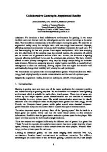
Figure 1: A route in dark blue where tracking was done using velocity-based DR . This route goes through a garden, a small street, a church and ends using a narrow street on an historical place of Grenoble (France) whose model (scale: 1/604) made of wood, paper, silk, metal and built from 1839 to 1848 in shown on the right. The corresponding GPS track is in light blue.
A BSTRACT This paper focuses on Mixed Reality Browsers (MRB) on mobiles that merge real and virtual worlds somewhere along the continuum that connects completely real environments to completely virtual ones. The concept of Mixed Reality comes from the fact that the real-virtual dichotomy is not sharp, but smooth over a continuum. Idealized notions of reality and virtuality can be thought of as endpoints on a continuum. Augmented Reality (AR) mode refers to all cases in which the auditory or visual display of an otherwise real environment is augmented by means of virtual sounds or graphic objects. The converse is Augmented Virtuality (AV), where a virtual world, one that is generated primarily by computer, like with 3D or 2D graphic, panoramas or maps, is being augmented with the audio-visual content of Point of Interest (POI). Pedestrian navigation enables user interaction with content by choosing where to walk and how to move through the augmented city. The introduction of mobile augmented reality browsers has forced a rethink on what kind of reality should be offered. Mobility induces a need for virtuality to free the user or developer of the necessity to go each time in the real world. Mobility is then the main reason behind the concept of Mixed Reality Browsers. By its intrinsic characteristics, MRB support advanced MR applications like remote maintenance, assisted navigation, cultural heritage visits, social cohesion by sharing with others. MRB browsers have to incorporate at their heart several kinds of tracking technology, both optical and non-optical. Optical tracking is based on vision technology and is therefore suitable for Micro-navigation. Non-optical tracking technology can be classified on the basis of three kinematic orders. Position-based tracking relies on external signals such as GPS to compute the user position and orientation in LLAH coordinates (latitude, longitude, altitude, heading). Velocity-based tracking uses dead reckoning to ∗ e-mail:
[email protected] † e-mail:
[email protected] ‡ e-mail:
[email protected]
compute displacement and heading change The velocity vector is computed using virtual or real proprioceptive signals like step detection, rotary speed and landmarks validation. External signals are not mandatory and there is no real distinction between indoor and outdoor. By putting the human in the loop and leaving the trust-me-you-are-there approach, velocity-based AR can be made the less demanding form of precise AR at the energy and hardware level. Acceleration-based tracking uses inertial navigation involving double integration of linear accelerations and simple integration of rotary speed to obtain displacement and heading changes. It works both indoor and outdoor and needs a specific hardware to be incorporated in shoes. Audio is the media which allows to make augmented cities accessible to visually impaired people, but audio is also well suited to velocity-based AR as the user don’t have to stop to get localized information. Audio clutter management has to be carefully designed with priority and waiting lists. Positional audio offers the faster way to indicate landmarks. However its use has to take into account the precision of the tracked position and orientation, as speech is difficult to spatialize and pure audio is imperative. We use a declarative format for positional audio with synchronization between audio chunks using SMIL. This format has been specifically designed for the type of audio used in AR applications. The audio engine associated to this format is running on mobile platforms (iOS, Android). Our MRB browser called IXE use a format based on volunteered geographic information (OpenStreetMap) and OSM documents for IXE can be fully authored inside OSM editors like JOSM. This is in contrast with the other AR browsers like Layar, Juniao, Wikitude, which use a Point of Interest (POI) based format having no notion of ways. This introduces a fundamental difference and in some senses a duality relation between IXE and the other AR browsers. In IXE, Augmented Virtuality (AV) navigation along a route (composed of ways) is central and AR interaction with objects is delegated to associate 3D activities. In AR browsers, navigation along a route is delegated to associated map activities and AR interaction with objects is central. IXE supports multiple tracking technologies and therefore allows both indoor navigation in buildings and outdoor navigation at the level of sidewalks. A first android version of the IXE browser will be released at the end of 2013. Being based on volunteered geographic
2 RELATED WORK 2 R ELATED W ORK 2.1 Position-based AR Position-based AR relies on external signals such as GPS outdoor or UWB indoor to compute user position and orientation in LLAH coordinates (latitude, longitude, altitude, heading). In urban area, GPS is lacking precision and UWB is very expensive. But both are very easy to set up and use to build AR application. An interesting on-going project on position-based AR accessible navigation is described in [14].
information with a full authoring system, we hope that it will allow building accessible pedestrian networks in augmented cities. Keywords: Augmented Reality, Pedestrian navigation, Walking space, Physiology, Visually impaired people, Browsers, HTML, Mobile communication, Web-based architecture. Index Terms: H.5.5 [Sound and Music Computing]: Modeling—; H.5.1 [Multimedia Information Systems]: Augmented Reality—
hal-00872721, version 1 - 14 Oct 2013
1
I NTRODUCTION
2.2 Velocity-based AR Velocity-based AR uses Dead Reckoning (DR) to compute displacement and heading change. The velocity vector is computed using virtual or real proprioceptive signals like step detection, virtual audio step feedback, rotary speed and landmarks validation. A velocity-based PDR-based system works by integrating human factors allowing people to be independent when navigating in indoor and outdoor environments. Two main schools have been active during the last 15th years, one in Switzerland and one in Japan. In Switzerland, two doctoral works on dead reckoning were started in 1998 [11, 16] at Polytechnic School of Lausanne (EPFL) and a Pedestrian Navigation Module combining a GPS receiver, three accelerometers, three magnetic sensors and a barometer was build in collaboration with Leica Vectronix. The PNM was conceived to be interfaced with navigation software. Commercial success was found in the military domain for infantryman by using several IMUs on the legs and waist allowing the monitoring of all kind of movements. In fact, it was more or less a shift towards technologies used to create synthetic avatars for movies. Following this work, development of map-matching algorithms combined with the use of the PNM were done [31]. A similar approach to the Swiss school was followed in Japan at AIST [15] but going one-step further by bringing AR guidance annotation and the use of 3D synthetic models computed on the fly. The PNM is positioned at the center of gravity of the body as was done by the Swiss school. Then this Japanese approach to dead reckoning was regularly enhanced with action recognition called PDR+, map-matching, image-based recognition, structure and motion algorithms, use of RFID tags, IMES spots and even obstacle detection [32]
A pedestrian navigation system has to cope with many cooperating tasks referring to different levels of precision, from vision-based micro-navigation to global navigation passing through IMU-based macro-navigation. Micro-navigation builds upon embedded software ability to create a greater awareness of immediate environment, using texture-based tracking or vision algorithms and relating this information to map and IMU data. Micro-navigation includes avoiding obstacles, locating a clear path in the proximate surroundings or at a complex crossing, finding objects, giving help when interacting with machines and providing absolute positioning using landmarks or beacons. Micro-navigation works at a precision level of a few centimeters by using predefined landmarks or 3D models. Macro-navigation refers to the actions required to find a way in a larger, not immediately perceptible environment and builds upon carefully designed pedestrian-ways incorporating speech instructions, audio guidance, environmental queries and IMU instructions among other things. Macro-navigation works at a precision level of a few steps using carefully designed routes with map-matching instructions. There is a duality relation between micro-navigation and macro-navigation. Micro-navigation is based on a localization system giving an absolute position in a local coordinate system that allows computing a relative position with respect to the planned route. Macro navigation is based on a localization system giving a relative position that allows computing an absolute position on the route through a process called map-matching. As a consequence, these two kinds of navigation complement and enhance each other. Global navigation is based on an absolute global localization system like the GPS. Its precision is that of a few meters if used in an adequate geographical environment where data from external sensors is accessible. It can be use to bootstrap macronavigation that can in turn be used to bootstrap micro-navigation. The join use of micro, macro and global navigation, allows building richer and more precise AR mobile applications in such fields as cultural heritage visits, outdoor games and people guidance. There are many ways to join micro, macro and global navigation. For augmented cities, the use of global navigation is difficult because of the poor precision of the GPS on sidewalks. It is better to use IMUbased macro navigation, with GPS giving absolute positioning only at some points where GPS variance is known to be low. Macronavigation cant be used alone for precise registration of close-range objects but can greatly reduce the database search space for computer vision, making it much simpler and more robust. Visually impaired people have difficulties navigating indoors and outdoors but they seek independent travel and have considerable success at it. By trying to understand the reasons behind this astonishing successful navigation, we have been led to put the human in the loop and leave the trust-me-you-are-there approach. This simplified approach has made practical and reliable a velocity-based AR that is very competitive at the energy and the hardware level by using only a smartphone in the hand or the pocket of a jacket. Dead reckoning, positional audio cues and very detailed structured environment representation that are probably the navigation aids used implicitly by visually impaired people are the main ingredients of our navigation system. We will explain how these concepts have been implemented using phones sensors, augmented reality audio and OpenStreetMap representation of regular indoor or outdoor layouts.
2.3 Acceleration-based AR Acceleration-based tracking uses sensors on or in the shoes to compute stride length (distance) and/or heading. This involves double integration of linear accelerations and simple integration of rotary speed to obtain displacement and heading changes. Drift due to the accelerometers can be removed by using the fact the velocity goes to zero when the foot hit the ground (Zero Velocity UPdaTe or ZUPT). The accuracy of the ZUPT based solution depends on the time interval between ZUPT points. For walking or running these conditions occur once on every footfall, that is, about once every second [12]. In 2000, Dynastream in Canada produced the first commercial Speed and Distance Monitoring (SDM) for Nike. Since then, they have developed products for several sports brands such as Adidas, Polar and Garmin. Sensors on the shoes are connected wirelessly to the phone and only stride length is computed (no heading computation). SDM uses an algorithm that integrates the 3D acceleration signals to calculate an intermediate variable between speed and acceleration that is linearly related to speed. The main result is that SDM knows when stride length change even if cadence is the same, a problem that has to be solved in velocity-based tracking by using several physiological models. This problem happens for example in presence of incline plane or when people detect obstacles. Acceleration-based tracking computing both distance and heading, appears in 2005 using more expensive MEMS sensors on the shoes connected through a wire to a computer. These precise
2
3 IXE Tactile Map at the Entrance
Live Map
Figure 2: Accessible map of a the entrance of Sugimotocho JR Railway station and its live version with DR tracking on a mobile phone.
hal-00872721, version 1 - 14 Oct 2013
professional systems are used for first-responders [10, 29, 7]. An open source embedded foot-mounted INS implementation including both hardware and software design has been created recently [4, 22].
latency and processing time, its use was not feasible on mobile. PapaEngine [2] pretends to be the first real-time HRTF-based rendering engine on mobile (iOS only). Another trial to implement an HRTF-based rendering engine was done at the University of Aalborg but was not successful due to processing time[23]. Interactive positional audio is the de-facto standard in AR applications. In positional audio, the effect of lateralized sound in headphone listening can be produced using amplitude and delay differences in the two earphone channels. Texture-based audio on mobile is quite new. It allows rendering natural phenomena like sound due to running water. The Topophonie research project uses granular dynamic sound rendering and explores new paradigms and methods of navigation in audio-graphic clusters. They have implemented on mobile an audio engine for content-based synthesis [6]
2.4 Audio AR Interactive positional audio is a very important modality in a situation of mobility, the creative and technological potentials of location-sensitive, mobile spatial audio being very high. As such, interactive audio is well suited to velocity-based AR as the user don’t have to stop to get localized information [18, 17, 19]. Implementation of interactive positional audio is done through an approach called Data Driven Audio that allows sound designers to make sounds, implement interactivity, and deliver event and sound bank files to programmers. The programmer has just to start a sound and update context-driven parameters. Audio engines implementing the concept of data driven audio are said to be cue-based. A good example of a cue-based audio system is FMOD [1], a popular game audio development system used to create sophisticated interactive soundtracks for iOS and Android games. FMOD is completely data-driven, meaning the program starts a cue, and then modifies real-time parameters to make transition from one segment or audio chunk to the next. Data driven audio is well suited to AR audio where the user perceives a mix of natural sounds and those generated by the application. Sound sources are distributed around us: some are fixed, other are mobile. As listeners, we evolve in a space and constantly mix the sources that surround us. That experience is what we call sound navigation[33]. When audio sources are visible and produce sound at the same time and in the same place as a visual manifestation, we call them audio-visual sources. Verbal and audio cues are short sounds effects that play to alert a user to a certain event. Cues-based audio engines are the most appropriated audio system for AR navigation. The normal way that human beings localize sound is based on the input - the pressure - at the two ears. The basic idea of 3D audio is that it should be possible to synthesize this sense of direction by controlling the pressure at the two ears. A normal way of controlling this is by using earphones. A given sound can then be synthesized as coming from a certain direction by applying specific filters. These filters are known as head related transfer functions (HRTFs). By convolving with the HRTFs, a sound can be made to sound as if it came from the direction given by the HRTF. Several HRTFs databases exist with different resolutions for direction. Using HRTF-based audio for navigation has been used and extensively tested [13]. However until now due to
3 IXE Velocity-based tracking together with volunteered geographic information can be a basis to create accessible augmented town by enabling the use of optical tracking technology for very precise augmentation. Volunteered geographic information allows creating a network of routes both indoor and outdoor (at the level of sidewalk) is a reasonable time. We have even built an electronic kick-scooter for that, the so-called Google car being not usable indoor and on sidewalks. Velocity-based tracking has a precision that is well suited to audio, as sound sources cannot be rendered with the high precision achievable through optical tracking. At contrarious, audio is a very immersive media when used in augmented reality applications. An AR navigation system can be build other three concepts: • Continuous localization by using embedded sensors together with physiological models of walking and assumptions about walking in structured environments. • Detailed Maps used both for map-aided positioning and environmental queries. • Guidance and navigation through AR audio, both 3D and environmental, with mixing of synthetic and natural sounds and support for timely audio information presentation. These concepts are inter-dependent and bringing them together is a way to find new solutions to problems that are difficult to tackle when looking at them independently. Taking into account these observations, we have designed IXE (Interactive eXtensible Engines) an urban AR pedestrian navigation system running on mobile
3
4.1 Allothetic and idiothetic cues
4 VELOCITY-BASED AR NAVIGATION
hal-00872721, version 1 - 14 Oct 2013
Figure 3: Velocity-based AR Navigation
4.1 Allothetic and idiothetic cues
phones with onboard geographic data and routing engine. IXE has shown that a precision of a few steps is attainable, guidance being done through a mix of spatialized vocal instruction and 3D audio. With IXE, the distinction between indoor and outdoor is blurred as a velocity-based location engine can run indoor and outdoor as demonstrated by the route shown on figure 1. Following the web paradigm, IXE is a browser for XML documents describing navigation networks: by using the concept of micro-format, one can define inside OpenStreetMap a rich format for pedestrian navigation networks allowing navigation at the level of sidewalks or corridors. The big advantage of doing this instead of defining a new XML language is that we can use standard OpenStreetMap editors like JOSM to produce these walking networks in a short amount of time. The authoring of an augmented city or at least of its key walking routes is then made possible. The purpose of the IXE browser is to read these OSM documents and generate from them visible or audible navigation information. IXE works on any mobile phone (iOS and Android). Its heart is composed of two engines hence its name (Interactive eXtensible Engines), one for velocity-based tracking and the other one for interactive audio, both cue-based, allowing quick reconfiguration for extremely varied applications. There are many position-based brower with micro-navigation. Among them, Argon [21] is one which goes a far wawy in using web technologies, but IXE is the only DR-based browser which can greatly reduce the burden on computer vision algorithm developers by providing an approximate starting position [10]. We are working on an IXE-SDK to help building location-based services using computer vision algorithms.
Idiothetic cues are cues generated by self-movement. There are three kinds of natural idiothetic cues that are available to a user allowing him to keep track of self-motion: • cues coming from the vestibular system (vestibular can be think as a physiological IMU). • cues coming from proprioceptors (muscle and joint receptors). • cues coming from the optic flow. These cues can be augmented with two kinds of synthetic idiothetic cues: • cues coming from the IMU sensors. • cues coming from virtual proprioceptors like realtime audio step feedback. • cues coming from a camera. Allothetic cues (visual and auditory) are external landmarks or beacons allowing a user to locate himself. They can be counted upon as references over quite long periods of time. These cues can be categorized in three groups depending upon the distance away: near, medium and far away. Each of this group has a specific role in orientation. These cues can be augmented with synthetic audiovisual cues which are the primary cues generated by AR applications. 4.2 Piloting and Dead Reckoning
4
V ELOCITY - BASED AR N AVIGATION
Piloting as shown on figure 3 uses allothetic cues. There are different levels of complexity in navigation when piloting. At one level, the user navigates to a salient cue such as a visual or auditory beacon. At another other level, relational properties of two or more ambient cues are used, the target itself need not be visible. In this type of navigation, the user creates a spatial map of his environment. Piloting can be used alone without recording movements to assist it but it does need to learn about the allothetic cues that will be used for guidance. A simulation system is useful to repeat the navigation before to try it in the real world, a good opportunity for MR system.
People navigates using cues generated by their own movements (self-movement cues or idiothetic cues), as well as the cues they encounter in their environment (distal cues or allothetic cues). These cues can be used to navigate in two different ways. When dead reckoning, they integrate self-movement cues over time to locate a present position or to return to a starting location. When piloting, they use allothetic cues as beacons, or they use the relational properties of allothetic cues to locate places in space [36]. Figure 3 shows a schematic view of our velocity-based tracking system.
4
5.4 Heading Error Correction
5 DEAD RECKONING
Dead reckoning as shown on figure 3 uses idiothetic cues. Dead reckoning can be completely self sufficient using idiothetic cues or it can be assisted by allothetic cues to correct or update a position, maintain a heading direction, or even initiate dead reckoning. A navigation system may use any combination of allothetic and idiothetic cues, natural or synthetic and can easily switch between cues. Experimentation is required to determine which cues are the best to be used in any situation. 5
D EAD R ECKONING
hal-00872721, version 1 - 14 Oct 2013
5.1 Stride Length Computation Step detection is important to avoid false or missed detections that can cause considerable errors in the estimation of the walking distance. Analysis of human walking has revealed some properties of the acceleration measured at the center of gravity of the person (located at the lower abdomen) or the thorax. Indeed, we note that at each step, the vertical acceleration makes a positive peak that can be used to count the steps. This works even if the mobile is held in the hand in front of the person but in a stable manner. The sensitivity of the peak detector has to be adapted to the chosen position for the mobile. Once steps are detected, the objective is to have the best walking distance accuracy. Different walking physiological models can be used to estimate step length or speed and there exists several formula relating vertical acceleration amplitude to speed [32]. For people who walk without changing the gait, a formula expressing a linear relation between step frequency and speed can be used after a calibration procedure whose parameters are pre-learned during a static calibration stage that can consist of a short walk or dynamically during a walk between to reference points. This calibration value is unique and reflects the walking characteristics of each pedestrian. In presence of stress, which is often the case with blind people when they detect an obstacle, the speed is lowered but the step frequency is kept the same. Walking-in-place where the stride length is zero is at one end of the spectrum. Then another formula, which relates the acceleration amplitude to speed, has to be used. There exist several such formulas that are to be calibrated to the user. A fusion of these two physiological models can be implemented by switching from the former model to the later one when there is a high discrepancy between them.
Figure 5: Tactile-Paving Route in Osaka used for DR experiments
In velocity-based DR tracking, we have to correct the distance and the heading as shown on figure 5. Heading correction is done first followed by distance correction. 5.4 Heading Error Correction Due to these constraints on the motion of pedestrians, an edge or way is a good predictor for the heading of the pedestrian. To use this predictor, we need to select a likely way when there is one. The walker can leave a way at an intersection, because of obstacle avoidance and simply to take a shortcuts as shown on figure 7. In these cases, we cannot temporarily correct the drift of the gyroscope by using the orientation of the way. We need then to start an edge selection algorithm to determine the next edge after an intersection, an obstacle avoidance or a shortcut. Hopefully, the topology of the network allows to reduce the set of likely segments dramatically. We use a data structure optimized for quick traversal between edges (ways) and vertices (nodes). We search for edges that meet two conditions or a combination of them: • The segment lies within a pre-defined distance from the user position. • The segment has a direction within a pre-defined angle from the current user heading. Curve-to-curve matching (with three steps) using a discrete approx∫ imation of ||a(t) − b(t)| | can be use at an intersection. This corresponds to a simple use of a more general method called Dynamic Time Warping [34]. Once a way has been selected, we can proceed to heading correction by aligning progressively the heading given by the gyroscopes with the heading of the way.
5.2 Heading computation The heading is the angle between true north and direction of the walk. Filtration of gyroscope data can be based on step frequency . Classical data fusion using accelerometers and gyroscopes is then used to compute the attitude of the mobile in the hand or in a pocket and to obtain by projection the heading vector. Absolute heading positioning can be done with the help of the compass, but magnetic disturbance have to be taken into account especially indoor.
5.5 Distance Error Correction Distance error is by using: • Topology to bound the error on the distance, by preventing the position to cross a wall as shown on figure 6.
5.3 Distance and Heading Error Correction through Map-Matching
• Projection on the navigation network proportional to the distance from the way as shown on figure 6.
Map-matching is one of the key elements to be used with DR tracking to remove drift of the real or virtual sensors and to obtain a good localization. By reading a digital map, indoor and outdoor navigation networks can be represented in memory as node-edge data structures on which graph algorithms can be used. These algorithms use the fact that most of the time the pedestrian environment is highly structured. In the real world, most routes inside buildings happen along straight lines defined by corridors and walls, with dominant directions. In Outdoor, pedestrian crossing, sidewalks, pedestrian streets, poles, alley in gardens, small street in historical city center, are constraints for pedestrian navigation. We are experimenting a lot on tactile paving networks as found in Japan because they offer a wonderful testbed for DR navigation (see figure 5).
• Landmarks detected by the user cues where we simply snap the position to the location confirmed by the user. Projection on the navigation network for dead reckoning was found to work very well. Landmark’s detection by the user was also found very useful during testing in Sugimotocho Stn (Osaka) in april 2013 (Figure 6). It improves the perception of reliability and the confidence of the user in the system without putting a burden on him as confirmed by visually impaired people. Idiothetic cues detected by the user and announced in advance by the audio system were found very useful (figure 6) and that was probably the
5
6 EVALUATION OF VELOCITY-BASED DR TACKING
Figure 4: Navigation using only phone’sensors and based on dead-reckoning based is sensitive to gyroscope drift (left). With the help of a map, this drift can be corrected (center) as well as the distance computed using physiological models (right). The route shown is inside a public building and is passing through stairs to go from floor level 2 to floor level 1. No landmark validation was necessary to navigate in this building.
hal-00872721, version 1 - 14 Oct 2013
Trough Walls & Gyro drift
Trough Walls
Fulll Map-matching
Sugimotocho Stn.
Figure 6: Map-Matching using topological information.
6
main step towards having a reliable and safe DR navigation system on which LBS can be based. As we have seen, the navigation network allows to correct both heading and distance, but the walker is allowed to leave this network, i.e. the system will continue to track him until he reaches again the network. However this wandering must be limited in time and distance otherwise the drift will be too strong for the system to be able to recover a position on the network. Our first objective was to allow bypassing of obstacles and navigating in crowded walking space. For this to work, the movements must not involve to many changes of orientation. With our current implementation of DR tracking, we found that for indoor navigation, halls of moderate size without ways can be crossed. In outdoor the distance can be longer if we are in a space where the GPS location gives reasonable precision (figure 7).
E VALUATION OF V ELOCITY - BASED DR TACKING
There are many ways to estimate the precision. One is to use reference positions which can be obtained in a number of different ways, e.g.: • The person returns to the starting position enabling an easy mean of estimating position error. • The person passes over, and possibly stops at a number of pre-surveyed reference positions. • The person is equipped with a camera which positions itself accurately towards pre-installed visual markers at known positions. The first two approaches are easy to employ and do not require any extra equipment. The first approach brings in very few information on what happens during the walk. The second approach requires the test person to restrict his motion, which may lead to different movement patterns than is the case in real scenarios. The third approach is a little complex to implement. As we have a map and our system is able to plot the estimated positions on the map in realtime, the better solution by far is when walking to look both at the position on the screen and in the real world. The problem we faced to implement this approach was the limited zoom level available with all map kits found on mobile phones. At this level of zoom, it’s very difficult to estimate on the map the computed position with a precision of two or three steps that is the level of precision we are looking for. This led us to implement our own map visualization system using HTML5 technologies (SVG) enabling an infinite zoom. We use the OpenStreetMap format for both indoor and outdoor geographical data representation [28]. But maximum zoom of OSM tiles visualizers is 18 for computational and delivery reasons. After many experiments, we found necessary to remove this limit to be
Figure 7: Leaving the navigation network two times for crossing a bassin of gravels a lawn
6
7.1 Environnemental Queries
8 AUDIO AND VELOCITY-BASED AR
INRIA Research Institut (Grenoble)
Sugimotocho Railway Station (Osaka)
Urban Park (Grenoble)
hal-00872721, version 1 - 14 Oct 2013
Figure 8: Sensors Monitoring and Evaluation through large-scale visualization
able to monitor the quality of the localization. A visualization software has been build using OpenLayers library [5] based on Open Web Platform languages (HTML5, CSS, ECMAScript, SVG, etc.). This library allows us to easily use an OpenStreetMap layer until zoom level 18. In order to add information and make more accurate the visualization, we choose to add SVG models as layers to indoor or outdoor map. OpenLayers does not allow us to add an SVG document inside a defined bounding box, that is why we build a new OpenLayers addin [5]. Beyond zoom level 18, our viewer remove OSM tiles to let only the SVG map on screen. SVG maps can be authored easily and we took this opportunity when doing experiment in railways stations to use the same design as tactile Japan Railways (JR) maps located at the entrance of the stations(figure 2. We were then able to get them live on the phone through DR tracking. Tracking was found to work nicely in the two railways station for which we have build a model (Sugimotocho Stn and Wakayamadaigakumae Stn, both in Kansai). Tracking was not lost even when going through stairs and elevators. Models of the station were build in august 2012 with the help of our electronic kick-scooter. 7
role="to"/> tag k="content:resource" v="garden.html"/> garden.xml audio document
AUTHORING THE AUGMENTED C ITY
OpenStreetMap is by far the most used volunteered geographical information system and allows representing data at the level of sidewalks or corridors inside building. OpenStreetMap uses a topological data structure, with three elements, nodes, ways and relations. Relations are just groups of nodes, ways or relations themselves. Semantic data in the form of key-values pairs can be associated to each of these three elements. This very simple and open schema allows inserting in an openStreetMap document landmarks and beacons useful for localization purpose, together with references to multimedia content. The relation element can be use for many AR structure like audio-visual panoramas referencing synthetic audio cues or 3D objects. The main advantage of having an OSM document as a master document for the augmented city is the ease of authoring. Indeed, the main OpenStreeMap editor JOSM can be used to produce easily a navigation network for the augmented city containing allothetic and idiothetic cues for tracking, together with all the references to audio and visual AR objects. The example below which describes an audio-visual AR panorama gives an idea of the power of such a langage based on OpenStreetMap: