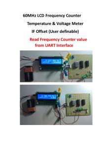
µPD78F9835 Microcontrollerbased Frequency Counter, Capacitance and Inductance Meter and Seismic Data Logger
Submission for EDN/NEC Cornelius Van Drebble Mad Design Contest By Dmitrii Loukianov
December, 2004 1
Abstract This document describes the design, software and operation of a versatile microprocessorbased Frequency Counter, Inductance and Capacitance meter. The instrument is based on NEC EV9835 microprocessor evaluation board and additional measuring circuit board. The following features of the NEC microcontroller are highlighted: external event timer/counter, interval timer, dot matrix LCD controller, interrupt subsystem, keypad controller, battery power control. The instrument is intended for standalone use as a service tool, and also as a data logger for the seismometer with an inductive displacement sensor. The instrument contains minimum number of precision capacitors, and, if necessary, these elements may be calibrated in the field. The calibration data is stored in the on-chip flash memory. The unique resolution and capability to measure low inductance and capacitance values, measuring deviation from the preset values and charting the deviation make this universal instrument handy and suitable for many measurement and data logging applications.
Introduction The need for automated measurement of various electrical and non-electrical parameters is ubiquitous in today’s life, both in industrial and consumer applications. When a nonelectrical parameter (like temperature or humidity) is measured and logged, it is usually first converted into an electrical value by an appropriate sensor. Many of physical parameters may be converted to analog voltage or frequency or pulse duration. However, frequency and time measurements are the most accurate due to the fact that they may be performed by counting the periods of very accurate frequency source, like a crystal oscillator, that does not depend on the battery voltage and other environmental conditions. As the parameter is represented by pulses or pulse train, which are naturally digital, it is also easy to send the output of the parameter-to-frequency converter to the measurement unit over long wires or optical links without degradation of accuracy. For that reason, the described meter is based on accurate frequency measuring, rather than on other features like ADC, and the other analog measurements are performed as a side product with the help of transducer. The design goal was to maximize the use of the on-chip peripherals of the microcontroller, minimize the external circuitry cost and achieve maximum versatility by implementing most of the high-level features in software, and do only time-critical functions in hardware. To reduce the number of components, all glue logic is combined into inexpensive FPGA (the design uses approximately half of XC9572XL device). The measurement circuit reconfiguration is performed without manual switches, to allow software modify and sequence measurements. For instance, the period measurements are preceded by rough frequency estimates to ban modes that will result in erroneous measurements. The smart measurement automatically selects the most appropriate measurement settings, and the output is represented in intuitive form (25.17256 MHz rather than 25172560Hz, 3.452 nF instead of 3452 pF, etc). The relative, delta and mean/standard distribution can also be supported. The instrument should have a limited number (two) of accurate components, and should use software calibration instead of tunable elements. The accuracy and calibration is discussed below.
2
Measurement Capabilities The instrument can operate in following modes: •
Frequency Counter A – in this mode, the frequency of input signal up to 100MHz can be measured with the resolution of up to 0.5Hz.
•
Period Measurement A – in this mode, period of input signal is measured with the resolution of 200ns.
•
Frequency Counter C – in this mode, the frequency of input signal in the range of 25-2500MHz is measured with the resolution of 10-6.
•
Duration A-B – in this mode, the time distance between the edges of signals applied to inputs A and B is measured with the resolution of 200ns. Both rising and falling edges on each input may be selected as a start and stop for the time measurement.
•
Crystal Test – in this mode, the frequency of a fundamental mode of crystals can be measured in the on-board oscillator circuit. The oscillator can operate within 100kHz – 40MHz range.
•
Inductance – in this mode, the inductance in the range of 10mH – 10nH can be measured in a LC-tank setup with the resolution of ~0.1nH. This method is very sensitive and suitable for measuring parts used in RF circuits.
•
Capacitance Small – in this mode, the capacitance in the range of 50nF – 1pF can be measured with the resolution of ~0.1pF in LC-tank circuit. This method is very sensitive and suitable for measuring parts used in RF circuits.
•
Capacitance Large – in this mode, the capacitance in the range of 1000uF – 1nF can be measured in the dual-slope integrator circuit
In above mentioned modes, the relative (offset) measurements can be performed, for instance, to eliminate the effects of stray capacitance or inductance, or to evaluate the deviation and frequency drift. The microcontroller can store the reference measurement and subtract it from the current measurement results before display. The difference may be displayed as numerical value, or may be plotted as analog bar in the graphic display. The instrument can be used as a data logger, for instance, to display the temporal variations of the measured parameter. In one of the intended applications {not included in reference design}, the pendulum seismometer with a displacement-to-frequency converter is used as a frequency source, and the frequency deviations are displayed as a seismogram on a graphics display.
3
Figure 1. Meter’s Block Diagram
Prototype Construction The prototype is build with two boards – one is the NEC’s EV9835 board and another is a 2layer SMD board which contains measurement circuits, power converter and input BNC connectors (Figure 2). The board is connected to the NEC’s EV9895 board by a header connector. The pin numbering corresponds to the expansion port connector found on the evaluation board. The measurement board schematic is shown in the Appendix 1, and the block diagram is shown in Figure 1. The board has a CPLD with glue logic, implemented in VHDL, see Appendix 2. The CPLD contains the simple measurement circuit, prescaler for frequency measurement, SPI interface for loading configuration and SPI interface expander for controlling other programmable devices, like PLL circuit LMX2336 used as a highfrequency prescaler and crystal oscillator, and analog switch ADG714 used to reconfigure the LC measurement circuit.
4
Figure 2. Measurement Board Prototype
Measurement Circuits There are two independent measurement circuits in the instrument – frequency/time path and analog oscillators. Each is described in detail in next sections. Reader’s familiarity with NEC uPD78F9835 microcontroller architecture and programming is assumed.
Frequency Measurement The frequency measurement path block diagram is shown in the Figure 3. Part if it is implemented in XC9572XL CPLD device. The circuit is configured by the microcontroller via SPI interface, implemented as bit-bang software toggling ports P3.1..P3.3. The source of the measurement can be InA, InC, Crystal oscillator and Analog oscillator. The source is selected by the multiplexor MUX1. Since the frequency measurement will be performed by the on-chip counter/timer 80, the maximum count frequency is limited to 5
5MHz, which is not sufficient for a decent frequency counter. If the frequency at the output of MUX 1 is above 5 MHz, it can be divided by 64 in a 6-bit ripple counter. The measured frequency is gated by the measurement interval strobe, that is generated by Gate Logic from the reference frequency, obtained from the output of timer 82, and Gate_Enable signal generated on pin P2.6 of the microcontroller by software.
Figure 3. Frequency measurement circuit
The gate duration for frequency measurement in the instrument must be within 1ms – 100s, and should be at least as accurate as one period of the max counted frequency (10-50V/uS should be selected. This will yield the delays within