1
Measurements of Acoustic Pressure and Velocity Vector in Source Localization using Acoustic Intensity Sensors
Khalid Miah Literature Survey EE 381K Multi Dimensional Digital Signal Processing, Spring, 2005
Abstract – Identifying acoustic sources in terms of their relative location is an important factor in active noise control. Traditional source localization measurements uses scalar pressure sensors which proved to be less accurate. Nehorai et al. proposed a different approach for source localization using vector natured acoustic intensity sensors. Four-dimensional (4-D) intensity based algorithm for direction-of-arrival (DOA) estimation both in free-space and reflecting boundary scenarios were investigated. Numerical simulation for both cases showed higher performance than that of scalar sensor. Experimental results from anechoic chamber supported the fact that vector sensors were more accurate in terms of source localization than scalar pressure sensors.
2 I. INTRODUCTION It is important to identify acoustic sources in terms of their relative location for variety of practical applications. Localization of acoustic sources using vector sensor models were analyzed and then compared with scalar sensors in this report. The time difference of arrivals of the acoustic waves between the sensors are used for source localization [1]. Nehorai et al. proposed a novel approach of source localization using an array of vector sensors whose output is a vector corresponding to acoustic pressure and acoustic particle velocity. The main advantage of these vector sensors over traditional scalar sensors is that they make use of more available acoustic information. Thus vector sensors outperform scalar sensor arrays in accuracy of source localization [2], [3].
In this report, direction-of-arrival (DOA) of sound sources were estimated using vector sensors utilizing statistical properties of the acoustical fields. A useful quality measure for direction estimation in 3-D space is the normalized asymptotic mean-square angular error (MSAE) between unit vector at the sensor pointing toward the source and its estimate. Algorithms for estimating DOA using 3-D covariance and 4-D intensity methods were developed [2] for free-space scenario. Intensity based algorithm has been extended to account boundary reflection for DOA estimation where vector sensors are free floating in the water column, located on the seabed, or on the ground [4]. Due to lack of proper experimental data and software required for implementation, numerical simulation was limited to free-space measurements. Methods of DOA estimation described in this report can be used in passive acoustic surveillance systems without giving away the location of the probe itself.
3 II. BACKGROUND
A quality measure for direction-of-arrival (DOA) estimation in 3-D space is the normalized asymptotic mean-square angular error (MSAE) between u and its estimate uˆ . In this report, u is a unit vector at the sensor pointing towards the source, that is cos θ1 cos θ 2 u = sin θ1 cos θ 2 sin θ 2
(1)
where θ1 and θ 2 are the azimuth and elevation angles of u, respectively. Thus, θ1 ∈ [0,2π ] and θ 2 ≤ π 2 . The acoustic particle velocity and pressure at position r and time t
can be denoted as v(r, t) and p(r, t). Under the plane wave at the sensor assumption, it can be shown [12], [13] that v(r, t) =
u.
p(r, t ) ρ0 c
(2)
where ρ 0 is the ambient density and c is the sound speed in the medium.
Phasor representation of acoustic pressure and acoustic particle velocity vectors will be used in the measurement model. Then, the pressure part of the model can be derived to y p (t ) = P (t ) + e p (t )
(3)
Similarly, the velocity part of the measurement can be derived to y v (t ) = P(t ) .u + e v (t )
(4)
Now, combining (3) and (4), we have y p (t ) 1 e p (t ) = P(t ) + y v (t ) u e v (t )
(5)
where P(t) is the phasor representation of the acoustic pressure, e p (t ) and e v (t ) are the noise components of pressure and particle velocity vectors, respectively. Now, let δ be the angular error between u and its estimate uˆ , then δ = 2 sin −1 ( uˆ − u / 2 ) . Then MSAE can
{ ( )}
be defined as lim N E δ 2 . For a regular model [14], the MSAE of any regular direction N →∞
estimator is bounded from below by
4
{
}
MSAE CR = N. cos 2 (θ 2 ).CRB(θ1 ) + CRB(θ 2 )
(6)
where CRB(θ1 ) and CRB(θ2 ) are, respectively, the CRB (Cramer-Rao Bound) variances of the azimuth and elevation angles of the source. Now, for a single-source single-vector sensor case, the CRB can be shown as CRB(θ) =
1 1 + ρ cos 2 θ 0 2 2 Nρ v ρ 1 0
(7)
It can be observed from (7) that ρ v is the signal-to-noise ratio (SNR) of the velocity measurement in each sensor component, while ρ is an equivalent SNR of both the pressure and velocity-vector measurements. Combining both (6) and (7), a compact expression for the lower bound of the MSAE of a single-source single-vector sensor measurements can be derived [2] as MSAE CR =
1+ ρ . ρvρ
(8)
III. 4 –D INTENSITY BASED ALGORITHM
In this section, 4-D intensity based algorithm for estimating DOA of a single acoustic source both in free-space and reflections boundary conditions is analyzed. Some of the key assumptions are plane wave at the sensor, homogeneous medium, and complex Gaussian noise with zero mean.
A. Free-Space Measurements This algorithm stems from the fact that the u is the unit vector in the opposite direction of the sound intensity vector. This algorithm computes 1 sˆ =
N
N
∑ Re{y p (t ) yv (t )}
(9)
t =1
uˆ = sˆ sˆ
(10) The statistical performance of this estimator is analyzed and for the Gaussian case, the ratio between the MSAE of this estimator and the MSAECR is
(
)
2
2
ρ 1+ ρ p σ p σv MSAE = 1+ = . MSAE CR ρ p (1 + ρ ) 1+ ρ
(11)
5 B. Reflection Boundary Measurements Acoustic Vector Sensor (AVS) located on the ground or seabed needs to account for boundary characteristics (reflection coefficient). Although the intensity based algorithm is used to estimate DOA, the 3-D intensity vector is not parallel to u. Therefore, the exact same method used for free space case cannot be used in this case to find the elevation angle of the source. A point source radiating spherical waves and known orientation of the AVS are two of the fundamental assumptions made for this method [4]. The measurement of a single AVS can be written as y(t) = hp(t) + e(t)
for t = 1, 2,…….., N
(12)
where h is the sensor’s steering vector and is defined [4] as
h =
1+ R (1 + R ) cos φ cosψ ) (1 + R ) sin φ cosψ (1 - R )sinψ
.
(13)
where φ and ψ are the azimuth and elevation angle of the source, respectively. Therefore, the reflection coefficient can derived [11] as R = where Z in = −
Z in − ρ 0 c sinψ Z in + ρ 0 c sin ψ
(14)
(1 + R )ρ 0 c . sin ψ (1 − R )
Based on the horizontal component of acoustic intensity, the azimuth of the source can be estimated from cos φˆ sˆ cos φ → uh ≅ uˆ h ≅ = . sin φˆ sˆ sin φ
(15)
Since the magnitude of the horizontal component of acoustic intensity depends on the elevation angle ψ , so will the accuracy of uˆ h . With proper modification, the analysis of the azimuthal estimator can be used to show that the asymptotic MSAE = lim N E (φˆ − φ ) = 2
N →∞
2
1+ 1+ R ρ 4
2 ρ 2 1 + R cos 2 ψ
(16)
where ρ = σ s2 / σ 2 is the signal-to noise ratio (SNR). Similarly, using the vertical component of the acoustic intensity, the elevation angle for the ground and seabed case can be estimated [4].
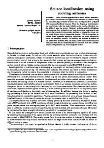
6 IV. IMPLEMENTATION A. Microphone Array Configuration The microphone array is one of the main components of the 4-D intensity measurements used for DOA estimation. The microphone array and related hardware & software used for data acquisition were developed by Schumacher [5] and Budhiantho [8] and modified by Tinianov [6] and Poterek [7]. The four element microphone array were arranged in an orthogonal pattern with one microphone (reference microphone) at the origin of a rectangular coordinate system. The remaining three microphone are each placed at a distance of 4 cm from the origin along the three axes of the coordinate system (see Fig. 1)
Fig. 1: 4-element microphone array configuration. The experiment was performed in an anechoic chamber located at the University of Texas, Austin ,TX. Microphones used in the array were connected to preamplifiers to amplify signals to a level appropriate to the computer data acquisition system. The amplifiers also limits the frequency response of the system to prevent distortion due to aliasing in A/D converter and to limit noise added by the amplifier itself [7]. Based on pressure measurements from the four microphones, three velocity vector components were calculated. Pressure and velocity data obtained from those measurements were then used for DOA estimation using Matlab.
7 B. Simulation
Based on Matlab simulation, performance between scalar and vector measurements for free-space case were compared and shown in Fig. 2. Due to time constraints and lack of available simulation software, reflection boundary measurements are not included in this report. Figure 3 (a) & (b) are taken from Hawkes paper [9] shows performance comparison for both free-space and reflection boundary measurements.
Fig. 2: Performance between scalar and vector sensor arrays in free space measurements. (simulation)
(a) (b) Fig. 3: Performance between scalar and vector sensor arrays in free space measurements (a) and reflection boundary measurements (b) [9].
8
V. CONCLUSION From simulation results, it can be concluded that vector array measurements performed better in comparison with scalar array measurements for free-space. The results could be improved by updating hardware for data acquisition and fine tuning the software used for simulation. Performance comparison made in Hawkes paper [9] clearly shows superiority of vector sensor measurements over scalar measurements. For free-space measurements case, 16% reduction in MSAE B achieved for sources at normal incidence, and it improved to 35% as the source approached grazing incidence. Similar performance were also shown for reflection boundary measurements.
VI. FUTURE WORK The direct extension of the intensity based DOA estimation algorithm would be optimization in the presence of multiple reflection boundaries. 3-D velocity based covariance algorithm can be investigated for DOA estimation for both free-space and reflection boundary cases. Different other methods such as Maximum Likelihood (ML) [10], cross-power spectral phase, and cross correlation [11] can be used for time-delay estimation. Comparison among those methods for various cases could be a feasible topic for PhD level research.
VII. ACKNOWLEDGEMENT I would like to thank Prof. Elmer L. Hixson for the idea and assistance about the acoustic intensity measurements using vector sensors.
9
REFERENCES [1] E. Paldi and A. Nehorai, “Performance Analysis of two Direction Estimation Algorithms using an Acoustic Vector Sensor ,” IEEE Proc. Int. Conf. Acoust., Speech Signal Process, Minneapolis, MN, pp. 360-363, April 1993. [2] M.Hawkes and A.Nehorai, “Surface-mounted acoustic vector-sensor array processing,” IEEE Proc. Int. Conf. Acoust., Speech Signal Process, Atlanta, GA, pp. 3170-3173, May 1996. [3] E. Paldi and A. Nehorai, “Acoustic Vector-Sensor Array Processing,” IEEE Trans. Sig. Proc., vol. 42, no. 9, pp. 2481-2491, September 1994. [4] M. Hawkes and A. Nehorai, “Wideband Source Localization Using a Distributed Acoustic Vector-Sensor Array,” IEEE Trans. Sig. Proc., vol. 51, no. 6, pp. 1479-1491, June 2003. [5] M. Schumacher, “A Transducer and Processing System for Acoustic Energy Density Measurements”, MS Thesis, The University of Texas at Austin, Austin, TX, December 1984. [6] B. D. Tinianov, “Further Work on Total Energy Density Measurements in a Reverberant Sound Field”, MS Thesis, The University of Texas at Austin, Austin, Texas, May 2000. [7] T. J. Poterek, “Energy Density Analysis of Acoustic Intensity”, MS Thesis, The University of Texas at Austin, Austin, Texas, May 2001. [8] M. H. W. Budhiantho and E. L. Hixson, “Acoustic Velocity related Distributions,” J. Acoust. Soc. Am., vol. 100, no. 4, pt.2, pp. 2838-2845, November 1996. [9] M. Hawkes and A. Nehorai, “Acoustic Vector-Sensor Processing in the Presence of a Reflecting Boundary,” IEEE Trans. Sig. Proc., vol. 48, no. 11, pp. 2981-2993, November 2000. [10] J. C. Chen, R. E. Hudson and K. Yao, “Maximum Likelihood Source Localization and Unknown Sensor Location Estimation for Wideband Signals in the Near-Field,” IEEE Trans. Sig. Proc., vol. 50, no. 8, pp. 1843-1854, August 2002. [11] B. C. Kirkwood, “Acoustic Source Localization Using Time-Delay Estimation”, MS Thesis, Technical University of Denmark, Lyngby, Denmark, August 2003. [12] P. M. Morse and K. U. Ingrad, Theoretical Acoustics, New York: McGraw-Hill, 1968. [13] A. D. Pierce, Acoustics – An Introduction to Its Physical Principles and Applications, New York: McGraw-Hill, 1981. [14] A. Nehorai and E. Paldi, “Vector-Sensor Array Processing for Electromagnetic Source Localization,” IEEE Trans. Sig. Proc., vol. 42, no. 2, pp. 376-398, February 1994.