Masonry Laboratory Website
University of Wyoming
MASONRY LABORATORY – FINAL REPORT The main objectives of this work are to provide instructional materials for masonry laboratory activities that can be used at other educational institutions and to review the use of non-destructive testing and evaluation methods as part of the masonry design course at the University of Wyoming. The masonry laboratory project at the University of Wyoming is complete. Samples of the lab website were provided to the sponsors in May 2007 and all suggestions have been incorporated into the project in the Fall 2007 semester. A complete summary including all data is included in a paper submitted to The Masonry Society (TMS) in June 2007, an article submitted to National Concrete Masonry Association (NCMA) in October 2007 and the thesis completed by John Coombs. The articles are included as Appendix A and B of this report and the thesis is incorporated into the website. Various software programs were used to construct the masonry laboratory website. These programs included: Macromedia Dreamweaver, Macromedia Flash and Adobe Premiere. Macromedia Dreamweaver was used to construct the web pages. Macromedia Flash was used to construct the animations used on the website. An animation was constructed used to illustrate five different bond wrench tests. Adobe Premiere was used to edit digital video clips recorded during the test. Video clips were condensed to show highlights such as specimen in loading apparatus, load application and failure in real time. Individual laboratories are listed and described in the following paragraphs. Module A – Masonry construction Lab 1 - Construction of masonry walls and prisms including mixing and testing mortar Lab 2 – Construction of masonry arches Module B – Masonry testing Lab 3 – Evaluation of bond strength of masonry prisms using bond wrench testing and modulus of rupture testing Lab 4 – Evaluation of compressive strength of masonry units and masonry prisms Lab 5 – Testing of student fabricated masonry arches Module C – Masonry field testing and evaluation Lab 6 – Use of thermal imaging to evaluate existing concrete masonry walls Lab 7 – Use of flatjack testing to evaluate existing masonry walls Module A-Masonry Construction Labs at the University of Wyoming Module A is designed to allow students to perform common masonry tasks such as building small masonry walls using different brick orientations. In this first lab, students also construct stack bond masonry prisms using different types of mortar. They mix the mortar to construct the walls and prisms. Lab 2 has students design and build a masonry arch, which is then tested in Module B. This task allows them to practice a design, build, and test process; an experience that is rarely available in a lecture setting. After construction students submit as-built drawings that reflect the changes that occurred
1
Masonry Laboratory Website
University of Wyoming
during construction, something that will confront them in future practice. Each group provides a hypothesis on how the arch will fail including failure locations. Module B-Masonry Testing Labs at the University of Wyoming Module B includes compressive strength, bond strength and arch testing. In Lab 3, bond strength is determined using two different methods: modulus of rupture test and the bond wrench test. The modulus of rupture test is performed using four-point bending in a servo-controlled Instron test machine. This test is a modified version of ASTM E518 and C67. The bond wrench test is applied to a prism clamped within a testing frame according to ASTM C1072. Lab 4 requires students to experimentally determine and compare the compressive strength of an individual brick and a three-unit prism. Through these tests students observe how individual components interact and how these interactions affect the physical characteristics of the whole system. Lab 5 engages students in testing structures where the failure mode can be unpredictable. As mentioned before in Module A, students are required to hypothesize how their arch will fail. The report will contain the student’s observations as to how the arch failed and how it contrasted with their prediction for the failure mode. The students also devise a plan to transport their arch such that it does not experience bond failure during transportation. If a groups arch breaks during transport, they assemble the pieces of the arch and continue with the testing; often times students are surprised by the amount of load that the arch can support in compression. Module C- Masonry field testing at the University of Wyoming At the University of Wyoming, a unique opportunity exists for students to perform flatjack testing on an existing masonry wall to estimate the modulus of elasticity and determine the stress acting on the wall. Initial measurements were completed before cutting slots in the masonry bed joints to position the flatjacks. The flatjack loading procedure was performed with students applying pressure to the wall and recording the pressure in the flatjack and the displacement between gage points. Another common technique used for NDE is infrared imaging across a wide variety of materials to evaluate their condition. Thermal images of a two story CMU wall indicate locations of grouted sections, ungrouted sections, the floor slab and potential grout seepage. Such images are presented in the classroom to introduce students to this NDE technique. Impact echo is another NDE technique and a lab incorporating this technology is currently under development. Discussion for sponsors The final lab website will be accessible to masonry professors through The Masonry Society (TMS) or Rocky Mountain Masonry Institute (RMMI) website and on CD format for distribution at activities such as the Masonry Professors Workshop. The laboratory website is approximately 300 MB. The PI recommends placing links to the website on all three sponsoring institutions websites. 2
Appendix A Development of Laboratories for Masonry Testing and Non‐Destructive Evaluation Vanessa L. Storlie Jennifer E. Tanner, PhD Introduction Using laboratories in a masonry course can enhance the learning experience. The main objectives of this work are to provide instructional materials for masonry laboratory activities that can be used at other educational institutions and to review the use of non‐destructive testing and evaluation methods as part of the masonry design course at the University of Wyoming. This course includes laboratories where basic construction, masonry testing, and field investigation are introduced. The laboratory experiments allow students to learn by another style as well as providing a setting in which the students and faculty member can develop interpersonal rapport. This environment also allows students to become excited about the material they are learning. Development of website materials to support laboratories To enhance laboratory experiences, the University of Wyoming has developed a website where students have access to laboratory procedures and sample data. Animations and videos of test procedures are included to illustrate these concepts. Screen shots of aspects of the website are shown in Figure 1 through 4. The development of this website has increased upfront costs but little or no recurring costs as with a traditional laboratory. This resource is intended to supplement actual laboratory experiments, but should not replace physical laboratory experiments. Unfortunately, engineering laboratory experiments require equipment, lecture, and faculty time. In cases where this equipment is not available, the masonry laboratories provide exposure to testing and may serve as a simple method to introduce experiments into the curriculum. The NDE portion of this website will introduce students to testing procedures such as flatjack testing and infrared imaging techniques without requiring other schools to purchase expensive equipment. Various software programs were used to construct the masonry laboratory website. These programs included: Macromedia Dreamweaver, Macromedia Flash, and Adobe Premiere. Macromedia Dreamweaver was used to construct the web pages, were created in design mode which allowed the user to view the future web page layout. The html programming mode could have been used, which would have allowed the designer to directly input html code to create the web page. Macromedia Flash was used to construct the animations used on the website. An animation was created to illustrate five different bond wrench tests. The dial moved and stopped at each measured load reading at the same time the brick rotates in the animation. Adobe Premiere was used to edit digital video clips recorded during the test. Video clips were condensed to show highlights such as specimen in loading apparatus, A‐1
load application and failure in real time. These short video segments were incorporated into the website. Laboratory Activities The laboratory activities are divided into three modules: A) Masonry Construction, B) Masonry Testing, and C) Non‐destructive Testing Procedures. Module A – Masonry Construction • •
Laboratory 1 – Construction of masonry walls and prisms including mixing and testing mortar Laboratory 2 – Construction of masonry arches
Module B – Masonry Testing • • •
Laboratory 3 – Evaluation of bond strength of masonry prisms using bond wrench testing and modulus of rupture testing Laboratory 4 – Evaluation of compressive strength of masonry units and masonry prisms Laboratory 5 – Testing of student‐fabricated masonry arches and development of final report
Module C – Non‐destructive Testing • •
Laboratory 6 – Use of flatjack test method to evaluate existing concrete masonry walls Laboratory 7 – Use of thermal imaging to evaluate existing concrete masonry walls
Module A‐Masonry Construction Labs at the University of Wyoming Lab 1 is designed to allow students to perform common masonry tasks such as building small masonry walls using a minimum of three unit orientations. Students also construct stack bond masonry prisms using different types of mortar. They mix the mortar to construct the walls and prisms. Next, students perform a more complicated task of designing and building a masonry arch, which is then tested in Module B. This task allows them to practice a design, build, and test process; an experience that is rarely available in a lecture setting. Typical formwork and partial construction are shown in Figure 5. After construction students submit as‐built drawings that reflect the changes that occurred during construction, something that will confront them in future practice. The final task that confronts the students is to determine how to move the masonry arch to minimize damage and provide a hypothesis on how their arch will fail and locations of failure. Module B‐Masonry Testing Labs at the University of Wyoming Module B includes compressive strength, bond strength and arch testing. Bond strength is determined using two different methods: modulus of rupture test and the bond wrench test. The modulus of rupture test is performed using four‐point bending in a servo‐controlled Instron test machine as shown in Figure 6. The bond strength is calculated based on geometric properties and the failure load. The bond wrench test is applied to a prism clamped within a testing frame as specified by the ASTM standards (Figure 7). Students determine the compressive strength of an individual brick and a three‐ A‐2
unit prism. Through these tests students observe how individual components interact and how these interactions affect the physical characteristics of the whole system. Masonry arch testing engages students in testing structures where the failure mode can be unpredictable. As mentioned before in Module A, students are required to hypothesize how their arch will fail. The final report will contain the student’s observations as to how the arch failed and how it contrasted with their prediction for the failure mode. The students also devise a plan to transport their arch such that it does not experience bond failure during transportation. If a groups arch breaks during transport, they assemble the pieces of the arch and continue with the testing; often times students are surprised by the amount of load that the arch can support in compression. The general failure mechanism is the formation of hinges and observation of individual pieces rotating as shown in Figure 9. Module C‐ Field Testing Lab at the University of Wyoming At the University of Wyoming, a unique opportunity exists for students to perform flatjack testing on an existing masonry wall to estimate the modulus of elasticity and determine the stress acting on the wall. Initial measurements were completed before cutting slots in the masonry bed joints to position the flatjacks. The flatjack loading procedure was performed with students applying pressure to the wall and recording the pressure in the flatjack and the displacement between gage points. Another common technique used for NDE is infrared imaging across a wide variety of materials to evaluate their condition. Thermal images of a two story CMU wall indicate locations of grouted sections, ungrouted sections, the floor slab, and potential grout seepage. Such images are presented in the classroom to introduce students to this NDE technique. Impact echo is another NDE technique and a lab incorporating this technology is currently under development. Summary The masonry laboratory and website are intended to introduce engineering students and faculty to laboratory activities. The use of a website will allow a larger number of students to be effectively engaged with these laboratory experiments. Universities that do not have the resources to perform these tests can utilize this resource in the classroom to have a web‐based laboratory. By virtue of the website’s intrinsic properties, the laboratories can be easily made available to professors and students for use. The masonry laboratory website is not meant to replace existing hands‐on laboratory sessions, rather to expand masonry curriculums and serve as a simple way to introduce masonry evaluation in a course. Acknowledgements This work was funded by National Concrete Masonry Association Research and Education Foundation; Portland Cement Association and Rocky Mountain Masonry Institute. The conclusions and views presented are those of the authors and not the sponsoring agencies. Atkinson‐Noland and Associates provided testing equipment and technical expertise related to the flatjack testing and radar images presented in this paper. A‐3
References Rand P.J., Brown R.H., Samblanet P., “Evaluation of Masonry Education in the United States and Canada,” Tenth North American Masonry Conference, St. Louis, Missouri, June 2007.
Figure 1: Website-homepage
Figure 2 Photograph page
Figure 3 Illustration of bond wrench testing
Figure 4: Video demonstration of laboratory activity
A‐4
Figure 5: Construction of masonry walls (2005, 2006 and 2007)
Figure 6: Construction of Masonry Prisms (2006 and 2007)
Figure 7: Masonry arch construction (2005, 2006 and 2007)
A‐5
Figure 8: Beam test of masonry prism
Figure 9: Bond wrench testing procedure a) prior to loading b) immediately after failure
Hinges
Figure 10: Masonry arch a) in test frame b) just prior to failure
A‐6
Initial gage length
Masonry saw cuts in wall
Figure 11: Schematic of flatjack testing procedure for determining modulus of rupture
Grouted section
Un-grouted section
Grout seepage
Second story
First story
Figure 12: Thermal imaging of a masonry wall
A‐7
Appendix B Development of Laboratories for Masonry Testing and NonDestructive Evaluation John M. Coombs, MS Jennifer E. Tanner, PhD Abstract This paper describes the outcomes of a project to increase masonry knowledge through field inspection and laboratories. A broad range of topics including traditional masonry material tests and state-of-the-art nondestructive testing methods have been created in the form of hands-on activities. Future engineers are better prepared to design masonry systems when exposed to masonry construction, test methods or field investigations. Non-destructive evaluation (NDE) methods applicable to masonry are introduced, including a laboratory and results of flatjack testing on an existing building at the University of Wyoming. Video and photos of these laboratories have been transferred into a website intended to be used in conjunction with existing masonry courses and laboratory programs or to provide guided independent study to engineering students. Introduction Introduction of laboratories within a masonry course is the focus of this paper that combines the following topics: learning styles; traditional laboratories; and field investigation. These three different topics are merged together to create much-needed resources for masonry education (Rand 2007). The primary objective of this work is to provide instructional materials for masonry laboratory activities that can be easily incorporated into the curriculums at educational institutions. The secondary objective is reviewing non-destructive test and evaluation methods (NDE) as part of the masonry design course at the University of Wyoming. The course introduces masonry behavior in the lecture setting as well as hands-on laboratories that were developed to facilitate understanding the behavior of masonry components and masonry systems, a concept vital to design practice (Drysdale et al. 1999; Atkinson 1991). Laboratory components include basic construction, masonry testing and field investigation. Forensic studies including nondestructive testing is an ever growing method to evaluate existing building conditions. As a result of the multitude of learning styles used by students, variety in teaching is essential to provide a well balanced curriculum. Educational theory has shown that most students benefit from the addition of laboratory or hands-on sessions during their education. Laboratories provide discovery learning not offered in traditional educational settings. (MacKenzie 1988) Participating in laboratory experiences naturally affords students opportunities beyond the traditional lecture setting. Felder developed a set of learning styles and compared them to teaching methods (Table 1). Engineering students learn best through intuitive, visual and active activities while engineering professors tend to teach from concrete, verbal and passive methods (Felder and Silverman 1998). This dichotomy makes B-1
learning more difficult for students and decreases the intellectual level of material presented in the classroom. Laboratories naturally promote kinesthetic teaching methods that directly correspond with students’ preferred learning styles making it easier for the students to assimilate knowledge. Another investigator, Lowman (1995) attributes intellectual excitement and interpersonal rapport as two dimensions essential for effective teaching. Both dimensions are equally important and must be implemented together to achieve exemplary teaching and to reach full teaching potential. Laboratories generally promote intellectual excitement and provide an opportunity for developing personal rapport. Overview of laboratory activities The laboratory activities are divided into three modules: A) Masonry Construction; B) Masonry Testing; and C) Non-destructive Testing Procedures. Each module has individual laboratories as outlined below. Module A – Masonry construction • Laboratory 1 - Construction of masonry walls and prisms including mixing and testing mortar. • Laboratory 2 – Construction of masonry arches. Module B – Masonry testing • Laboratory 3 – Evaluation of bond strength of masonry prisms using bond wrench testing and modulus of rupture testing. • Laboratory 4 – Evaluation of compressive strength of masonry units and masonry prisms. • Laboratory 5 – Testing of student-fabricated masonry arches and development of final report. Module C – Non-destructive testing • Lab 6 – Use of flatjack test method to evaluate existing concrete masonry walls. • Lab 7 – Use of thermal imaging to evaluate existing concrete masonry walls. Masonry Construction Module A is designed to allow students to perform simple and complicated tasks. Students build masonry walls incorporating a minimum of three unit orientations into each wall (Figure 1). In addition students build a stack-bond prism with the assistance of a jig to ensure the prisms are plumb. The prisms are later tested in a masonry testing module. During this process students mix mortar and evaluate the flow to ensure it is within acceptable limits for laboratory use. Visual aids such as Figure 2 are provided to allow students to visualize the process prior to the start of the laboratory. The most complicated masonry construction task is included in Laboratory 2 where students design and build an arch, a classic masonry structure. When combined with the corresponding testing laboratory, students get to practice a design, build, and test process; an engineering experience that is rarely available in normal course work. The first task is dedicated to planning and students must request supplies and tools to build the formwork. Typical formwork and partial construction are shown in Figure 3. This construction includes mortar joints with varying thicknesses based on the curved nature of the arch. B-2
Furthermore, a maximum number of brick are permitted requiring students to determine if it is possible to construct a multi-wythe section. After construction students submit drawings reflecting the as-built system and discuss changes. The changes in design and construction plans for the arch reflect the on-site changes that will confront them in future practice. The goal is to show future engineers that change is a part of improving and facilitating construction and not a criticism to their engineering skill. Students must also consider how to move the arch structure to minimize damage and provide a conjecture on possible failure modes and locations. Traditional testing procedures and results Module B is designed to allow students to achieve the following objectives: understand masonry testing procedures; calculate masonry bond strength; compare values from different testing procedures; calculate compressive strength; and comment on observed results. Prisms are first tested in a beam orientation where failure generally occurs in the center dividing the prism into two separate three-unit prisms. One of the resulting prisms is subsequently tested in the bond wrench device as the second portion of Laboratory 3. The other three-unit prism is capped and tested in compression during Laboratory 4. Bond strength is obtained from two methods, the modulus of rupture and bond wrench testing procedures. Modulus of rupture testing is performed through four-point loading the prism in a servo-controlled Instron test machine. Bond failure should occur at the location of maximum moment. The maximum bond stress is calculated based on geometric properties and the failure load. The test procedure shown in Figure 4 is similar to ASTM E518 with a modification to allow for specimens constructed of 6 brick. The bond wrench procedure is applied to a prism clamped within a testing frame as specified by ASTM C1072. A load is applied through a lever arm creating a cantilever beam (Figure 5). ASTM C1072 is the most commonly used bond strength test due to its ability to test every joint in a masonry prism, not just the middle joint as in ASTM E 518. It is easy to both fabricate specimens for and conduct the testing of both these tests, which has led to its widespread use. (PCA 1994a) The resulting bond stresses are shown in Table 2 and Table 3. Bond wrench data are within ranges of other flexural bond studies and beam data are at the low end of bond strength results (Hedstrom et al. 1991; Ghosh 1991; Wood 1995). It is interesting to note that the bond wrench values are consistently higher than the beam test results. The authors attribute this to stress concentrations in the beam if the specimen is not level during testing. Beam test results are more sensitive to poor tolerances or a non-plumb specimen than the bond wrench testing program. In future testing, the beam specimens will be carefully shimmed to reduce this experimental error. Students determine the compressive strength of individual brick and multiple unit prisms modeling a masonry system to observe how all the components of the masonry system interact and how those relationships affect the physical characteristics of the system as a whole. Prisms are capped to provide a level loading surface. Load is applied through a universal compression test machine (Figure 6). The stress is calculated by dividing the load by the area and students compare these test results to typical values of the specified compressive strength of masonry. Compressive strength testing also allows students to observe and describe the failure mode of vertical cracking. A complete free-body B-3
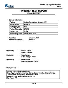
diagram of a three-unit prism is shown in Figure 7. Mortar has a higher Poison’s ratio than brick; this results in lateral expansion of mortar that is restrained by the brick. Lateral tension is generated in the masonry unit and vertical cracks form perpendicular to those tensile stresses shown in Figure 8 (Drysdale et al. 1999). As expected, prism test results are considerably lower than the individual brick compressive strength (Table 4). Masonry Arch Testing Masonry arch testing engages students in testing structures where the failure mode can be unpredictable. Prior to testing, each student postulates a failure mode. The final report requires students to explain the observed failure mode and contrast that to their predictions. As previous mentioned, students must plan how to transport the structure to the test frame and each year typically one group experiences bond failure during the transportation phase of the laboratory. In cases where arches break, the group assembles the pieces of the arch; students are surprised to learn that placing pieces of the arch together takes advantage of the compressive strength properties and the structure sustains several times its own weight. The general failure mechanism is through forming hinges and observing rotation of individual pieces as shown in Figure 9. Students discuss the observed failures in their final report. Non-destructive testing methods Module C is designed to expose students to an example of a continuously progressing new technology where improved techniques become available both for data acquisition and processing. As many of the United States’ historical masonry buildings are aging and will require maintenance or repair, NDE is a viable alternative to evaluate their condition and strength instead of using techniques which would limit their use or cause destruction of the buildings. Engineers in the workplace need to continually learn about state-of-the art methods in testing and design such as NDE. For example, the laboratory on flatjack testing permits students to see this process and analyze the recorded data. Flatjack testing procedure A unique opportunity existed at the University of Wyoming to perform flatjack testing on an existing masonry building to estimate the modulus of elasticity and evaluate acting stress in a wall. Preliminary measurements and cuts in the wall were made prior to the lab. The flatjack loading procedure was performed with students applying pressure to the wall and reading measurements. Each student was engaged in some part of the testing process. The modulus of elasticity is determined through using two cuts and placing displacement measuring gages between the cuts (Figure 10). Load is applied to both cuts and the change in displacement measured (Suprenant and Schuller 1994). The slope of the resulting graph is the modulus of elasticity. Results from this procedure indicate a modulus of elasticity of 940 ksi (6481 MPa) which is very close to the code value for masonry with a specified compressive strength of 1500 psi (10.3 MPa) (Figure 11). Axial load in a wall is determined by applying gage points to an existing wall. The initial gage length is recorded prior to making a cut in the mortar between these points, resulting B-4
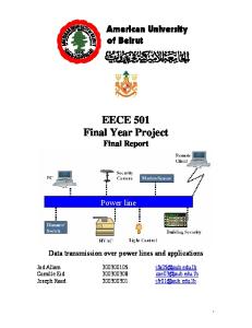
in a shortening of the gage length. Flatjacks are placed in the masonry cut, load is applied, and both the flatjack stress and gage length are recorded at predetermined intervals. When the measured gage length reaches the initial gage length, the stress in the flatjack is the actual axial stress in that section of the wall. (Suprenant and Schuller 1994) Both of these exercises can be conducted through modifications to an interior brick wall in the Engineering Building at UW. Preparation for the flatjack testing will occur through permanent cuts in the wall reducing the time to setup the lab. Students will arrive and perform the modulus of elasticity testing as well as axial load tests for each masonry course. Additional non-destructive testing methods Other non-destructive evaluation methods range from observational investigations to complex investigations. An assignment on observation of masonry architectural features and locating damage to masonry buildings is part of the masonry design course. Damage in the buildings is based on a presentation related to causes of cracking in existing masonry structures (Klingner and Grimm 2004). More complex investigations include pachometers, radar, infrared imaging and impact echo. Reinforcing bars are frequently located using radar images and cover meters or pachometers. Determining grout location and quality of construction can be completed using radar and infrared thermography. All three of these methods provide significant information without damaging the structure. Radar is used to determine the internal condition of materials and can be used to detect steel, plastics and other anomalies in constructed buildings. Ground penetrating radar uses a pulse of radiation energy emitted into a material and measures the return strength at different times to map the internal makeup of different construction systems. Radar reflections are returned when the emitted pulse of radiation energy crosses boundaries of different dielectric permittivity (Geophysical Survey Systems, Inc. 2006). As the pulse passes from grout to steel reinforcing bars a strong return is yielded. The animation of Figure 12 illustrates locating rebar and evaluating the depth based on the radar method. Infrared imaging is another common technique used for NDE across a wide spectrum of materials to evaluate condition. Infrared radiation is felt in the form of heat as all objects above zero degrees Kelvin emit infrared energy. A high resolution thermal camera is able to detect small temperature differences such as between concrete and masonry with maximum radiation intensity of around 10 um (Clark et al. 2003). To achieve a good thermal image, a temperature difference is needed and can be achieved through solar radiation and possibly cooling or heating one side of the wall. Thermal images of a two story CMU wall indicate locations of grouted sections, ungrouted sections, floor slab and potential grout seepage (Figure 13). Impact echo utilizes the propagation of sound waves through concrete and masonry to measure material thickness and identify material flaws. Sound waves propagate through the material, reflecting back at transition zones resulting from the presence of internal flaws or when an external surface is reached. Impact echo is used to locate cracks,
B-5
delaminations, voids, honeycoming and debonding in concrete and masonry. (Sansalone and Street 1997) Development of website materials to support laboratories To enhance laboratory experiences, the University of Wyoming has developed a website where students have access to laboratory procedures and sample data. Animation and videos of test procedures are included to illustrate these concepts. Screen shots of aspects of the website are shown in Figure 14. The development of this resource has increased upfront costs but little or no reoccurring costs as with a traditional laboratory. Boggs (2006) created a website reviewing biology test procedures and discovered that students who used the materials were more prepared for laboratories and frequently studied the material when completing the laboratory write up. This resource is intended to supplement laboratory experiences and the authors do on encourage replacing physical laboratories with computer-based activities. Unfortunately, engineering laboratory experiments require equipment, lecture and faculty time. In cases such as these, the masonry laboratories provide exposure to testing and may serve as a simple method to introduce laboratory experiences into a curriculum. The NDE portion of this website may introduce students to specialized testing procedures such as flatjack testing, radar and infrared imaging techniques without the need for purchasing expensive equipment. Summary This project is intended to expand the auditory and visual learning of the engineering student to include tactile or kinesthetic learning methods through laboratory sessions. With laboratories available to introduce basic masonry construction practices, building of masonry systems, testing bond strength, compressive strength and nondestructive evaluation, students are expected to better grasp the field of masonry as a whole. Laboratories expose students to practical experience beyond existing masonry textbooks. Students with a good grasp of the mechanics and characteristics of construction practice, failure, material characteristics, and testing both nondestructively and destructively, should provide more concise, efficient and construction friendly designs. Furthermore, they will be better equipped to troubleshoot and work with existing masonry because of familiarity with current field testing and evaluation methods. Finally, a module was created to allow students to experience NDE, a viable alternative to evaluate the condition and strength of masonry. By combining traditional masonry investigation along with new and expanding nondestructive evaluation techniques, a thorough and in depth evaluation of masonry can be accomplished. The inclusion of these state-of-the art techniques into the masonry curriculum significantly augments students’ laboratory experience which will be carried with them into the future. A greater number of students may be more effectively engaged by making these laboratory experiences accessible through a website. Educators will be given another tool to reach out to students. Testing opportunities may be limited at universities that do not have the resources to perform or utilize these tests in class; with implementation of a B-6
web based laboratory, all students, no matter the facilities, can take part in this expanded classroom. By virtue of the website’s intrinsic properties, the laboratories can be easily transferred and made available to professors and students for implementation and use. The computer version of laboratories is not meant to replace any existing hands-on laboratory sessions, rather the goal is to expand masonry curriculums and serve as a simple way to introduce masonry evaluation in a course. Acknowledgements This work was funded by National Concrete Masonry Association Research and Education Foundation; Portland Cement Association and Rocky Mountain Masonry Institute. The conclusions and views presented are those of the authors and not the sponsoring agencies. Atkinson-Noland and Associates provided testing equipment and technical expertise related to the flatjack testing and radar images presented in this paper. The authors express appreciation for an introduction to masonry laboratories in the masonry course taught by Richard E. Klingner at The University of Texas at Austin. References American Society of Testing Materials (ASTM), Standard Specifications, West Conshohocken, PA. C270 Standard Specification for Mortar for Unit Masonry C1072 Standard Method for Measurement of Masonry Flexural Bond Strength E518 Test Method for Flexural Bond Strength of Masonry Atkinson, R.H., 1991, “Effect of Loading Platen Thickness on Masonry Unit and Prism Strengths,” The Masonry Society Journal, V. 10, No. 1, August, pp 86-94. Boggs, C. N., 2006, The Virtual Edge: Design, Development and Evaluation of Virtual Laboratories for a General Microbiology Classroom, Doctoral dissertation, University of Wyoming, pp 102. Clark M.R., McCann D.M., Forde M.C., 2003, “Application of Infrared Thermography to the Non-Desctructive Testing of Concrete and Masonry Bridges” NDT&E International, V 36, pp 265-275. Drysdale, Robert G.; Hamid, Ahmad A.; and Baker, Lawrie R., Masonry Structures: Behavior and Design, Second Edition, Boulder, CO: The Masonry Society, 1999, pp 888. Felder, Richard M. and Silverman, Linda K., 1988, “Learning and Teaching Styles in Engineering Education,” Engineering Education, V. 78, No. 7, pp 674-681. Geophysical Survey Systems, Inc., 2006, What is GPR, Geophysical Survey Systems, Inc., http://www.geophysical.com/WhatIsGPR.htm, (accessed February 27, 2007). Ghosh, S.K., 1991, “Flexural Bond Strength of Masonry: An Experimental Review,” The Masonry Society Journal, February, pp 64-73. Hedstrom, Edwin G.; Tarhini, Kassim M.; Thomas, Robert D.; Dubovoy, V.S.; Kingner, R.E.; and Cook, R.A., 1991, “Flexural Bond Strength of Concrete Masonry Prisms Using Portland Cement and Hydrated Lime Mortars,” The Masonry Society Journal, February, pp 8-23. Klingner R.E., Grimm C.T.; “Masonry Cracks: Causes and Prevention” The Masonry Society, CD presentation, January.
B-7
Lowman, Joseph, Mastering the Techniques of Teaching: Second Edition, San Francisco, CA: Jossey-Bass Publishers, 1995, pp 344. MacKenzie, I.S., 1988, “Issues and Methods in the Microcomputer-Based Laboratory,” The Journal of Computers in Mathematics and Science Teaching, V. 7, pp 12-18. Portland Cement Association, 1994a, Bond Strength Testing of Masonry, IS277. Portland Cement Association, 1994b, Factors Affecting Bond Strength of Masonry, IS278. Rand P.J., Brown R.H., Samblanet P., “Evaluation of Masonry Education in the United States and Canada,” Tenth North American Masonry Conference, St. Louis, Missouri, June 2007. Sansalone, Mary J. and Streett, William B., Impact-Echo: Nondestructive Evaluation of Concrete and Masonry, Ithaca, NY: Bullbrier Press, 1997, pp 339. Suprenant, B.A. and Schuller, M.P., Nondestructive Evaluation & Testing of Masonry Structures, Addison, IL: Hanley-Wood, LLC, 1994, pp 194. Wood, Sharon L., 1995, “Flexural Bond Strength of Clay Brick Masonry,” The Masonry Society Journal, February, pp 45-54. List of Tables Table 1: Learning styles defined by Feldman and Silverman (1998) Table 2: Modulus of rupture results of masonry prisms through beam tests Table 3: Modulus of rupture results of bond wrench testing of prisms Table 4: Compression test results List of Figures Figure 1: Pictures of website a) home page b) photograph page c) animations used to illustrate radar d) video demonstration of laboratory activity Figure 2: Construction of masonry wall and prism Figure 3: Procedure to determine masonry flow Figure 4: Masonry arch construction Figure 5: Beam test of masonry prism Figure 6: Bond wrench testing procedure a) prior to loading b) immediately after failure Figure 7: Compression test procedure Figure 8: Complete free-body diagram of three unit masonry prism Figure 9: a) expansion of mortar without restraint b) lateral loads required to restrain mortar Figure 10: Masonry arch a) in test frame b) just prior to failure Figure 11: Schematic of flatjack testing procedure for determining modulus of rupture Figure 12: Flatjack testing results Figure 13: Illustration of inverted parabolas locating reinforcing bar and considering reinforcing bar depth Figure 14: Thermal imaging of a masonry wall indicating location of floor slab and grouted cells
B-8
Table 1: Learning styles defined by Feldman and Silverman (1998)
Dimensions of Learning and Teaching Styles Preferred learning Style Perception
Corresponding Teaching Style
Sensory
Content
Concrete
Intuitive Input
Visual
Abstract Presentation
Visual
Auditory Organization
Inductive
Verbal Organization
Deductive Processing
Active Reflective
Understanding
Sequential
Inductive Deductive
Student participation Perspective
Active Passive Sequential
Global
Global
Preferred learning style for engineering students Common presentation style for engineering lectures Table 2: Modulus of rupture results of masonry prisms through beam tests
Group PCL 1 PCL 2 PCL 3 PCL 4 PCL 5 Average COV
Load lbs (N) 663 (2950) 499 (2220) 540 (2400) 354 (1580) 497 (2210)
Stress psi (kPa) 104 (719) 78 (540) 85 (590) 56 (380) 78 (540)
Group MC 1 MC 2 MC 3 MC 4 MC 5 MC 6 Average COV
80 (550) 22%
Load lbs (N) 472 (2100) 525 (2340) 466 (2070) 426 (1900) 641 (2850) 513 (2280)
Note: a=5.25 in (133 mm), I=30.27 in4 (12.60x106 mm4) and c=1.81 in (46.0 mm)
B-9
Stress psi (kPa) 74 (510) 83 (570) 73 (510) 67 (460) 101 (695) 81 (560) 80 (550) 15%
Table 3: Modulus of rupture results of bond wrench testing of prisms
Group PCL 1 PCL 2 PCL 3 PCL 4 PCL 5 PCL 6 PCL 7 PCL 8 PCL 9 PCL 10 PCL 11 PCL 12 PCL 13 PCL 14
Load lbs (N) 175 (778) 200 (890) 150 (667) 190 (845) 215 (956) 220 (979) 190 (845) 160 (712) 230 (1020) 170 (756) 180 (801) 140 (623) 260 (1160) 160 (712)
Average COV
Stress psi (kPa) 141 (972) 161 (1110) 121 (834) 153 (1060) 173 (1190) 177 (1220) 153 (1060) 129 (889) 185 (1280) 137 (944) 145 (1000) 113 (779) 209 (1440) 129 (889)
Group MC 1 MC 2 MC 3 MC 4 MC 5 MC 6 MC 7 MC 8 MC 9 MC 10 MC 11 MC 12 MC 13 MC 14 MC 15 Average COV
158 (1090) 18%
Load lbs (N) 180 (801) 140 (623) 220 (979) 190 (845) 205 (912) 200 (890) 150 (667) 200 (890) 200 (890) 170 (756) 180 (801) 110 (489) 140 (623) 190 (845) 150 (667)
Stress psi (kPa) 145 (1000) 113 (779) 177 (1220) 153 (1060) 165 (1140) 161 (1110) 121 (834) 161 (1110) 161 (1110) 137 (944) 145 (1000) 89 (610) 113 (779) 153 (1060) 121 (834) 141 (972) 18%
Note: la=14 in (356 mm), lb=2 in (51mm), warm=8.95 lb (4.06 kg), wbrick=3.6 lb (1.63 kg), I=30.27 in4 (12.60x106 mm4) and c=1.81 in (46.0 mm)
Table 4: Compression test results
Group PCL 1 PCL 2 MC 1 MC 2 MC 3
Load kips (kN) 104 (463) 101 (449) 120 (534) 93 (410) 79 (350)
Stress ksi (MPa) 3.77 (26.0) 3.65 (25.2) 4.34 (29.9) 3.36 (23.2) 2.84 (19.6)
Group
Brick 1 Brick 2 Brick 3 Brick 4 Brick 5 Brick 6 Average 3.59 (24.8) Average COV 15% COV Note: Gross area of 3-5/8”x7-5/8” (92mm x 194mm)
B-10
Load kips (kN) 222 (988) 245 (1090) 205 (913) 168 (747) 219 (972) 279 (1240)
Stress ksi (MPa) 8.03 (55.4) 8.85 (61.0) 7.43 (51.2) 6.08 (41.9) 7.91 (54.5) 10.1 (69.5) 8.06 (55.6) 17%
Figure 1: Construction of masonry wall and prism
Figure 2: Procedure to determine masonry flow
Figure 3: Masonry arch construction
B-11
Figure 4: Beam test of masonry prism
Figure 5: Bond wrench testing procedure a) prior to loading b) immediately after failure
Figure 6: Compression test procedure
B-12
Masonry unit
Mortar (net compression)
Masonry unit (net tension)
Vertical crack
Mortar (net compression)
Masonry unit
Figure 7: Complete free-body diagram of three unit masonry prism
Mortar (net compression) Masonry unit (net tension)
vertical crack initiated
Mortar (net compression)
Figure 8: a) expansion of mortar without restraint b) lateral loads required to restrain mortar
B-13
Hinges
Figure 9: Masonry arch a) in test frame b) just prior to failure
Initial gage length
Masonry saw cuts in wall
Figure 10: Schematic of flatjack testing procedure for determining modulus of rupture
B-14
700 4.5 y = 940434x (psi) y=6484.1x (MPa) R2 = 0.9881
Stress (psi)
500
4 3.5 3
400
2.5
300
2 Group 1
200
Group 2 Group 3
100
1.5 1
Average Linear (Average)
0
0.5 0
0
0.0002
0.0004
0.0006
Strain (in./in. or mm/mm) Figure 11: Flatjack testing results
B-15
0.0008
Stress (MPa)
600
Figure 12: Illustration of inverted parabolas locating reinforcing bar and considering reinforcing bar depth
Grouted section
Un-grouted section
Grout seepage
Second story
First story
Figure 13: Thermal imaging of a masonry wall indicating location of floor slab and grouted cells
B-16
Figure 14: Pictures of website a) home page b) photograph page c) animation and photo used to illustrate bond wrench testing d) video demonstration of laboratory activity
B-17