Low-noise Amplifier for Neural Recording by
Rachna Srivastava
A thesis presented to the University of Waterloo in fulfillment of the thesis requirement for the degree of Master of Applied Science in Electrical and Computer Engineering
Waterloo, Ontario, Canada, 2015
c Rachna Srivastava 2015
I hereby declare that I am the sole author of this thesis. This is a true copy of the thesis, including any required final revisions, as accepted by my examiners. I understand that my thesis may be made electronically available to the public.
ii
Abstract With a combination of engineering approaches and neurophysiological knowledge of the central nervous system, a new generation of medical devices is being developed to link groups of neurons with microelectronic systems. By doing this, researchers are acquiring fundamental knowledge of the mechanisms of disease and innovating treatments for disabilities in patients who have a failure of communication along neural pathways. A low-noise and low-power analog front-end circuit is one of the primary requirements for neural recording. The main function for the front-end amplifier is to provide gain over the bandwidth of neural signals and to reject undesired frequency components. The chip developed in this thesis is a field-programmable analog front-end amplifier consisting of 16 programmable channels with tunable frequency response. A capacitively coupled twostage amplifier is used. The first-stage amplifier is a Low-Noise Amplifier (LNA), as it directly interfaces with the neural recording micro-electrodes; the second stage is a high gain and high swing amplifier. A MOS resistor in the feedback path is used to get tunable low-cut-off frequency and reject the dc offset voltage. Our design builds upon previous recording chips designed by two former graduate students in our lab. In our design, the circuits are optimized for low noise. Our simulations show the recording channel has a gain of 77.9 dB and input-referred noise of 6.95 µVrms (Root-Mean-Square voltage) over 750 Hz to 6.9 kHz. The chip is fabricated in AMS 0.35 µm CMOS technology for a total die area of 3 x 3 mm2 and Total Power Dissipation (TPD) of 2.9 mW. To verify the functionality and adherence to the design specifications it will be tested on Printed-Circuit-Board.
iii
Acknowledgements Here I will take the opportunity to thank all the people who supported me during my research work. First, I would like to thank my supervisor Professor Vincent Gaudet for supervising my work and guiding me in my research . He has been constantly supportive and his valuable inputs and excellent guidance always motivated and encouraged me. I am very thankful to Prof. Manoj Sachdev and Prof. David Nairn for reviewing my thesis and providing invaluable feedback. I must also thank to Prof. Mark Aagaard and Gangqiang Yang from his team for extending their support and guidance for Cadence Encounter flow for the chip. There were many other people who contributed during my research work. I would like to extend a special thank you to Dr. Brendan Crowley, one of the previous graduate students of our team for his support.His guidance is one of the key enabler for the project. I am grateful to all team members in my group Navid Bahrani, Manpreet Singh, Bahareh Ebrahimi, Chris Ceroici and Assem Hussein for their support and making my graduate experience a memorable one. I would also like to thank my fellow student Stanley Ituah for his invaluable support and feedbacks. It is worth mentioning the excellent support I had from ECE computer support staff. Thank you to Phil Regier for wonderful help with the CAD tools. I would also like to thank Jim J. Quinn from CMC Microsystems for his great support and feedback during the chip Tape-Out. Most of all, I want to thank my family, especially my parents, my husband and my son for their love and support and encouraging me in every possible way.
iv
Dedication This is dedicated to my husband and my son Daksh with lots of love.
v
Table of Contents List of Tables
ix
List of Figures
x
Nomenclature
xii
1 Introduction
1
1.1
Motivation and Application . . . . . . . . . . . . . . . . . . . . . . . . . .
1
1.2
Objective . . . . . . . . . . . . . . . . . . . . . . . . . . . . . . . . . . . .
4
1.3
Organization
5
. . . . . . . . . . . . . . . . . . . . . . . . . . . . . . . . . .
2 Background 2.1
7
Characteristics of Neural signals . . . . . . . . . . . . . . . . . . . . . . . .
7
2.1.1
Resting Membrane Potential . . . . . . . . . . . . . . . . . . . . . .
8
2.1.2
Action Potential
. . . . . . . . . . . . . . . . . . . . . . . . . . . .
9
2.2
Neural Recording Methods . . . . . . . . . . . . . . . . . . . . . . . . . . .
10
2.3
Characteristics and Challenges for Neural Recording Systems . . . . . . . .
13
2.3.1
Biocompatibility . . . . . . . . . . . . . . . . . . . . . . . . . . . .
13
2.3.2
Wireless Operation and Power Supply . . . . . . . . . . . . . . . .
14
2.3.3
Power Consumption . . . . . . . . . . . . . . . . . . . . . . . . . .
14
2.3.4
Noise Immunity and Form Factor . . . . . . . . . . . . . . . . . . .
15
History and State-of-the-Art Neural Recording Systems . . . . . . . . . . .
15
2.4
vi
3 Design of Field Programmable Analog Front-End Amplifier
22
3.1
Neural Recording Front-End Amplifier Specifications . . . . . . . . . . . .
25
3.2
Design Approach . . . . . . . . . . . . . . . . . . . . . . . . . . . . . . . .
25
3.3
Evaluation and Comparison of Available Design Choices . . . . . . . . . .
27
3.3.1
Fully Differential vs. Single-Ended Amplifier . . . . . . . . . . . . .
28
3.3.2
NMOS vs. PMOS resistors . . . . . . . . . . . . . . . . . . . . . . .
29
Design Blocks . . . . . . . . . . . . . . . . . . . . . . . . . . . . . . . . . .
30
3.4.1
Low-Noise Amplifier (LNA) . . . . . . . . . . . . . . . . . . . . . .
30
3.4.2
Second Stage Amplifier (High-Gain) . . . . . . . . . . . . . . . . . .
35
3.4.3
Digital-to-Analog Converter . . . . . . . . . . . . . . . . . . . . . .
40
3.4.4
Multiplexer . . . . . . . . . . . . . . . . . . . . . . . . . . . . . . .
41
3.4.5
Access to Internal Nodes . . . . . . . . . . . . . . . . . . . . . . . .
43
3.4.6
Digital Block . . . . . . . . . . . . . . . . . . . . . . . . . . . . . .
46
3.4
4 Simulation and Measurement Results 4.1
48
Simulation Results . . . . . . . . . . . . . . . . . . . . . . . . . . . . . . .
48
4.1.1
Low-Noise Amplifier . . . . . . . . . . . . . . . . . . . . . . . . . .
49
4.1.2
Second Stage Amplifier . . . . . . . . . . . . . . . . . . . . . . . . .
49
4.1.3
Recording Channel . . . . . . . . . . . . . . . . . . . . . . . . . . .
52
5 Conclusions
53
5.1
Summary and Contributions . . . . . . . . . . . . . . . . . . . . . . . . . .
53
5.2
Future Work . . . . . . . . . . . . . . . . . . . . . . . . . . . . . . . . . . .
54
APPENDICES
56
A Current and Voltage Reference
57
A.1 Design of Current Reference . . . . . . . . . . . . . . . . . . . . . . . . . .
57
A.2 Simulation and Test Results . . . . . . . . . . . . . . . . . . . . . . . . . .
61
vii
B Other Simulation Data
64
References
65
viii
List of Tables 2.1
Distribution of ions around neural cell membrane [1] . . . . . . . . . . . . .
9
2.2
State-of-the-art neural recording systems . . . . . . . . . . . . . . . . . . .
21
3.1
Comparison of fully differential and single-ended amplifier . . . . . . . . .
29
3.2
Comparison of different op-amp topologies. Referenced from [2](page 314)
31
3.3
Transistor sizing of LNA and its CMFB circuit. . . . . . . . . . . . . . . .
31
3.4
Transistor sizing of folded-cascode amplifier circuit. . . . . . . . . . . . . .
35
3.5
Transistor sizing of CMFB circuit for fully differential folded-cascode amplifier. 38
3.6
Capacitor values for channel . . . . . . . . . . . . . . . . . . . . . . . . . .
40
3.7
Transistor sizing of Miller amplifier . . . . . . . . . . . . . . . . . . . . . .
46
4.1
Comparison of different channel architectures
. . . . . . . . . . . . . . . .
49
A.1 Transistor sizing of BMR circuit. . . . . . . . . . . . . . . . . . . . . . . .
59
A.2 Transistor sizing of LNA-biasing circuit. . . . . . . . . . . . . . . . . . . .
61
A.3 Transistor sizing of folded-cascode biasing circuit. . . . . . . . . . . . . . .
62
A.4 Simulation values of biasing voltages. . . . . . . . . . . . . . . . . . . . . .
63
B.1 Monte-Carlo Simulations for FDNMOS channel . . . . . . . . . . . . . . .
64
B.2 CMFB loop stability analysis for FDNMOS channel . . . . . . . . . . . . .
64
ix
List of Figures 1.1
Block diagram of a conceptual Brain Machine Interface. . . . . . . . . . . .
3
2.1
The neuron membrane potentials. . . . . . . . . . . . . . . . . . . . . . . .
11
3.1
Measured noise in recording channel on PCB in AF5 chip. [Courtesy: Russell Dodd and Brendan Crowley] . . . . . . . . . . . . . . . . . . . . . . . .
24
3.2
Band-pass filter for neural recording channel. . . . . . . . . . . . . . . . . .
26
3.3
Generic architecture of neural recording channel. . . . . . . . . . . . . . . .
28
3.4
Schematic of LNA circuit and its CMFB circuit. . . . . . . . . . . . . . . .
32
3.5
Schematic of fully differential folded-cascode amplifier circuit. . . . . . . .
36
3.6
Schematic of CMFB circuit for fully differential folded-cascode amplifier. .
38
3.7
Second stage amplifier and compensating capacitor. . . . . . . . . . . . . .
39
3.8
5-bit DAC circuit. . . . . . . . . . . . . . . . . . . . . . . . . . . . . . . . .
42
3.9
Pass-transistor implementation of MUX cell. . . . . . . . . . . . . . . . . .
43
3.10 Architecture of 32x1 MUX (5-bit) circuit for DAC. . . . . . . . . . . . . .
44
3.11 Schematic of 8x1 MUX circuit for DAC. Here B0 , B1 and B2 are select signals for MUX and BN0 , BN1 and BN2 are complement of these signals. .
45
3.12 Schematic of Miller Amplifier circuit. . . . . . . . . . . . . . . . . . . . . .
47
4.1
Frequency response of the LNA. . . . . . . . . . . . . . . . . . . . . . . . .
50
4.2
Transient simulation of the LNA. . . . . . . . . . . . . . . . . . . . . . . .
50
4.3
Noise simulation of the LNA. . . . . . . . . . . . . . . . . . . . . . . . . .
51
x
4.4
Frequency response of the second-stage amplifier. . . . . . . . . . . . . . .
51
4.5
Frequency response of the recording channel. . . . . . . . . . . . . . . . . .
52
A.1 Schematic of Beta multiplier reference circuit . . . . . . . . . . . . . . . . .
58
A.2 Schematic of biasing circuit for telescopic and folded-cascode amplifier . . .
62
xi
Nomenclature ADC Analog-to-Digital Converter. 18 BMI Brain Machine Interface. 2 BMR Beta Multiplier Reference. 57 CMFB Common Mode Feedback. 30, 31 CMRR Common Mode Rejection Ratio. 24 CNS Central Nervous System. 1 DAC Digital-to-Analog Converter. 23 HCF High Cut-off Frequency. 52 LCF Low Cut-off Frequency. 52 LNA Low-Noise Amplifier. iii, 22 PSRR Power Supply Rejection Ratio. 24 TPD Total Power Dissipation. iii
xii
Chapter 1 Introduction
1.1
Motivation and Application
The human brain and its function has always been a topic of great curiosity for researchers. Neuroscientists strive to understand the mechanisms, i.e., the electrophysiological activities in the nervous system that correspond to, and cause, specific physiological actions. In recent years, the pace of research in the field of neuroscience has accelerated drastically. With a combination of engineering and neurophysiological knowledge of the nervous system, a new generation of medical devices is being developed to functionally link large groups of neurons in the Central Nervous System (CNS) with human-made recording systems [3]. By a direct interaction with the CNS, researchers are acquiring new scientific knowledge of the mechanisms of disease and innovating treatments for disabilities in patients who have a failure of communication between neural structures (or output to the 1
external environment) due to illness, stroke, or injury. The idea to build a direct functional interface between the brain and artificial devices has led to the establishment of a new area of research in the field of neuroscience, known as Brain Machine Interface (BMI). Figure 1.1 shows the block diagram of Brain-Machine-Interface. BMIs can provide solutions for disabilities like epilepsy and Parkinson’s disease. Epilepsy is a common brain disorder characterized by recurrent seizures. The invention of several neural recording systems has opened up avenues to make a significant change in the lives of the epilepsy patients [4]. Parkinson’s disease is a degenerative disorder of the central nervous system mainly affecting the motor system. Deep brain stimulation is one of the treatment methods for Parkinson’s disease. In this method, tiny electrodes are implanted in some specific part of the brain. Stimulating this part of brain often greatly reduces involuntary movements and tremors. This is the area where human-machine interfacing plays a great role in our health system. Developing a brain-machine-interface requires an accurate understanding of neurons and their performance. For the same, we should record and analyze neurons in their normal and excited modes. An understanding on the neural functioning helps us to determine a proper pattern for stimulating the brain [5]. This will also equip scientists to restore neurons functions in parts of the nervous system damaged by different diseases or paralysis. Scientists performed observations in animal and human neural network and they detected and recorded the action potentials of many neurons corresponding to motor control to develop analytical models that predict limb movements in real time. Some research groups have created prosthetic limbs that can duplicate the natural movement of human body parts [6]. Unlike passive artificial versions, these prosthetic limbs have the capability 2
Figure 1.1: Block diagram of a conceptual Brain Machine Interface. of moving independently and out of sync with its user’s movements. Cochlear implants and retinal stimulators [7] are excellent examples of successful neural interfacing technologies that have reached widespread clinical applications [8]. Future neuroprostheses are expected to be seamlessly integrated with the human body as much as possible and to use the most advanced developments in material science, data computing, electrical engineering and robotics. State-of-the-art neural interfacing microsystems capable of continuously monitoring large groups of neurons are being actively researched by leveraging recent advances in neurosciences, microelectronics, communications, microfabrication, packaging and miniaturization. Such microsystems are intended to directly tap into the source of voluntary control, the CNS, to feed prosthetic devices restoring or replacing sensory, motor, or cog3
nitive functions. One of the key components in these microsystems is known as the analog front-end circuitry. After probing the neural signal using microelectrodes, these signals are fed into this block. This block filters out undesired dc and high frequency components and amplifies the signals from an order of a few micro-volts to a range which is suitable for subsequent circuitry. Though many prosthetic devices have been successfully implemented in recent years, there still remain many issues and challenges concerned with the failure to meet the ’ideal’ requirements of a satisfactory prosthetic. It starts from finding the right material for the electrodes which are bio-compatible with the human tissues, long lasting wireless charging for the neural implanted devices, to making a prosthetic device which is easy to control, comfortable to wear, and cosmetically pleasing.
1.2
Objective
This neural recording project is a component of an ongoing collaboration with neuroscientists from the Faculty of Medicine at the University of Alberta. They are our clinical partners to do live testing of our neural recording chips. The chip developed in this thesis, called AF7 is a field programmable analog front end amplifier for a neural recording system and it consists of 16 programmable channels whose frequency response can be tuned to take care of the process variations of the chip into account. There was a previous generation of this chip (AF5) implemented by previous students in our research group in AMS 0.35µm CMOS technology. The fabricated chip was tested
4
on a custom PCB; while the chip was capable of recording, it was found to be too noisy for successful implantation. The goal of this thesis is to find the design gaps and issues with the previous generation chip and solve these issues with suitable architecture and design decisions. The previous generation chip used 4 blocks of 4 different channel architectures. The aim is to study the trade-off of the various channel architectures, with a consideration of low input-referred noise, bandwidth and stability. The target is to design a functional analog front end amplifier for neural recording system, aligned with the project specifications. To be consistent, our chip is fabricated in AMS 0.35 µm CMOS technology. The AMS 0.35 µm process technology has been selected for the fabrication of the chip, as it is very stable and well tested fabrication process technology with minimal fabrication issues. It has high yield and is inexpensive.
1.3
Organization
The organization for rest of the thesis is as follows. Chapter 2 presents the background information on neuron functionality, their characteristics and existing challenges for a highly efficient and feasible neural recording device. The different recording techniques and the specifications of neural recording systems are described further. A review of the works of various research groups involved in the design of neural recording systems is also covered. Channel architectures are analyzed with respect to input-referred noise, power con5
sumption and signal amplification factor, to find the best choice for the implementation of the recording channels in Chapter 3. The selected channel architecture used for implementing the neural recording system is discussed with its design details. Chapter 4 includes the simulation results for the front-end neural recording system. Chapter 5 gives a summary of the work done in the thesis. Conclusions and suggested future research problems are outlined.
6
Chapter 2 Background
2.1
Characteristics of Neural signals
The neuron is the basic working unit of the brain. It is a specialized cell designed to transmit information to other nerve cells, muscles, or gland cells. Neurons have a cell body (soma), an axon, and dendrites. There are over 10 billion neurons in the human brain [9]. An ion channel is formed in the neuron cell membranes with ions such as sodium, potassium, chloride, and calcium. To develop a neural recording system, it is important to have a basic understanding of neuron functioning. This chapter provides an insight in functioning of neurons.
7
2.1.1
Resting Membrane Potential
When a neuron is not sending a signal, it is considered to be ’at rest’. At this time the potential inside of the neuron is negative relative to the outside (approximately -70 mV). This potential is developed because the membrane that surrounds the neurons is semipermeable, which allows some ions to pass through and blocks the passage of other ions. The distribution of various ions is very different in intracellular and extracellular fluids. Table 2.1 shows the intracellular and extracellular concentration of these ions during rest [1]. Concentrations of K+ ions are mostly inside the cell (intracellular), and Na+ ions are mostly concentrated outside the cell (extracellular). There also exist other ions such as Ca2+ and Cl− , in lower concentrations. The concentration gradients for Na+ and K+ are set up by the active transport of Na+ and K+ by an Na+ /K+ ATPase known as the Na+ /K+ pump. ATPase pumps three Na+ ions out of every two K+ ions it puts in, finally when all these forces balance out, and the difference in the voltage between the inside and outside of the neuron is developed. At rest, a membrane is slightly permeable to K+ and almost impermeable to Na+ , which means that K+ will diffuse due to the concentration gradient and an electrical potential develops, with an excess of negative charge inside the neuron. The negative charge inside the neuron creates an electrical potential gradient which tends to pull positively charged ions into the cell. As the membrane is impermeable to Na+ , the only ion that can be attracted is K+ . The net flow of each ion across the membrane is zero at a particular voltage. At this voltage, the concentration gradient and electrical potential gradient of the ion reach equilibrium, and this voltage is called, equilibrium potential [1]. The voltage is 8
calculated using Nernst’s equation (2.1).
Vm = (RT /ZF )loge [Co ]/[Ci ] Where Vm is the voltage across the membrane (Vinside
(2.1)
membrane
- Voutside
membrane ),
R
is the gas constant, F is Faradays constant, T is absolute temperature in Kelvins, Z is valency of the ion. [Co ] and [Ci ] are the external and internal concentrations of the ion, respectively. Table 2.1: Distribution of ions around neural cell membrane [1] Ions Intracellular Concentration/(mM) Extracellular Concentration/(mM) Na+ 12 145 K+ 139 4 − Cl 4 120 − Large anions(A ) 140 2+ Ca < 0.0002 1.8
2.1.2
Action Potential
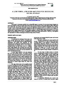
Neurons are excitable cells and they can generate and conduct action potentials. This is the one of the principal characteristics of neurons. Action potentials are rapid changes in the potential difference across the plasma membrane. The ability of neurons to generate action potentials is due to the presence of ion channels in their plasma membrane that respond to changes in the membrane potential. Figure 2.1 illustrates the different phases of an action potential which are due to the opening of two types of voltage sensitive channel, which are Na+ and K+ selective. The 9
different properties of these two types of channels determine the characteristics of the action potential [1]. The shape of the neuron membrane potentials remains fairly constant for all the neurons as shown in Figure 2.1. When a neuron is sufficiently stimulated, the Na+ ion channels open and diffuse Na+ ions through the cell, causing increased potential (depolarization). The potential required for opening K+ ions is larger than that needed for Na+ ions. Therefore, when the membrane potential is high enough, the K+ channels open. The Na+ channels close after 1ms. These two incidents produce repolarization, which decreases the membrane potential toward the resting potential level. The K+ ion channel will be closed for a period after that of Na+ , resulting in an undershoot. Eventually, the membrane potential reaches to resting state with the help of ion pumps [10].
2.2
Neural Recording Methods
The electro-physiological responses of the neurons can be measured using high-impedance microelectrode system penetrating 1-2 mm in the cortex [11]. When a neuron generates an action-potential (AP), the signal propagates down the neuron as a current which flows in and out of the cell. This method provides the highest degree of spatial specificity for the neural signals and it was most used method for measuring the action-potential through arrays of micro-electrodes earlier. The bioelectrical activity, transmitted along the axon of a neuron can either be measured intracellularly or extracellularly. Intracellular APs can be measured by penetrating
10
Action Potential
n lariza tio
n
Depo
0
tio lariza Repo
Membrane Potential (mV)
+30
Resting Potential
-70
1
2
3
4
5
6
Time(ms)
Figure 2.1: The neuron membrane potentials.
11
the membrane of a neuron with a sharp glass micropipette. This causes the death of the cell within a few hours after the recordings [8], so it is not recommended for chronic implants. In extracellular recording method, a micro-electrode with a sufficiently small tip [12], is placed adjacent to the neuron. In this method, the neuron action potential or spike is much smaller than that obtained with intracellular recording. Intracellular APs have amplitudes in the range of 70 mVpp (peak-to-peak voltage) [13], whereas extracellular APs have weak amplitudes ranging from 50 µVpp to 500 µVpp with a bandwidth of 100 Hz to 6 kHz, depending on the distance between the active neuron and the recording electrodes [14]. The summed electrical activity from many neurons can be recorded through lower impedance electrodes. The electrodes can be placed within the cortex (i.e., called Local Field Potential or LFP), just above the cortex (i.e., called subdural electrocorticography or ECoG), above the protective dura (i.e., called epidural ECoG), above the skull (subdermal) or above the skin(i.e., called electroencephalography or EEG) [15]. Local field potential (LFP) consists of lower-frequency neural waveforms (mHz to 200 Hz) having amplitudes ranging from 500 µVpp to 5 mVpp . LFPs are also recorded using extracellular microelectrodes. Extracellular neural signals reduce in amplitude in proportion of 1/distance2 . An EEG is a non-invasive method but ECoG is invasive as the electrode is implanted inside the skull yet outside the brain. A method is called invasive when the neuron activity is recorded directly from the cortex under the skull. Such methods require surgery and provide high spatial and time resolution at the same time. The LFP method is preferred to record the activity of a group of neurons located within millimeters while ECoGs and EEGs collect the neural signals over much larger areas, such as several square centimeters 12
at the cortical surface and scalp, respectively [16]. Initially, recording of the neural signals was limited to a single site, but during 1950s multi-electrode arrays were used to observe the simultaneous activity of many neurons in the brain. By observing the action potentials, or spikes, of many neurons in a localized region of the brain it is possible to gather enough information for that. As a result of improvements in the electronics and technology, the data processing speed has grown exponentially, which has enabled tremendous growth in the number of simultaneously recorded single neurons.
2.3
Characteristics and Challenges for Neural Recording Systems
Neural data is recorded from implanted multi-electrode arrays using bundles of fine wires and head-mounted connectors; then it is amplified and processed further. Chronically implanted multi-electrode arrays offer the best compromise between safety, recording longevity and neuronal yield required to operate BMIs. It works well in experimental settings, but many significant improvements are required before it becomes fully applicable for long-term (months to years) chronic clinical applications in humans.
2.3.1
Biocompatibility
Biological compatibility with human body is a big challenge for neural implants. Devices for neural recording and stimulation interact with neural tissues with different degrees of 13
precision and invasiveness. Neural recording and stimulation devices have generally been fabricated out of hard materials like silica, silicon or metals [17]. The mismatch in the stiffness of materials of the neuron and recording electrode contributes to tissue damage and decrease in recording quality. Also, the probe insertion itself produces a certain amount of initial damage. The implants are treated as foreign substance in the body so its very important to design and develop implants which are bio-compatible to the human tissues.
2.3.2
Wireless Operation and Power Supply
Another critical requirement for implantable recording devices is to replace the hardwired connections with a wireless link to eliminate cable tethering and risks of infection. Fully wireless implantable neural recording devices lower the risk of infection and patients have more freedom of movement and much better aesthetics. A wire line supply source in implantable neural recording devices makes the tissues highly prone to infections. Rechargeable batteries are seen as a promising source of energy. But the power must be delivered wirelessly across the skin through an inductive link formed by a pair of coils. Inductive coupling is among the safest methods, researched so far, to power up implants as it avoids wires [8]. Although maximizing wireless power transfer efficiency, to get a small physical battery size with a long life is still a challenge.
2.3.3
Power Consumption
The state-of-the-art multi-channel neural recording systems produce large quantities of continuously streaming data that must be transmitted for amplification and further pro14
cessing, yet the power dissipation of the small implanted devices must be strictly limited. Low power operation (