Low Latency Ethernet 10G MAC User Guide
Last updated for Altera Complete Design Suite: 14.0 UG-01144 Subscribe 2014.06.30 Send Feedback
101 Innovation Drive San Jose, CA 95134 www.altera.com
TOC-2
Low Latency Ethernet 10G MAC User Guide
Contents About this IP Core...............................................................................................1-1 Features......................................................................................................................................................... 1-1 Release Information.....................................................................................................................................1-2 Device Family Support................................................................................................................................ 1-3 Performance and Resource Utilization.....................................................................................................1-4 Transmit and Receive Latencies.................................................................................................................1-4
Getting Started.................................................................................................... 2-1 Introduction to Altera IP Cores................................................................................................................. 2-1 Installing and Licensing IP Cores.............................................................................................................. 2-1 Specifying IP Core Parameters and Options............................................................................................2-2 Parameterizing the IP Core........................................................................................................................ 2-3 Parameter Settings....................................................................................................................................... 2-3 Generated Files............................................................................................................................................. 2-5 Simulating Altera IP Cores in other EDA Tools..................................................................................... 2-6 Migrating from Ethernet 10G MAC to LL Ethernet 10G MAC............................................................2-7 Migration—32-bit Datapath on Avalon-ST................................................................................. 2-7 Migration—Maintains 64-bit on Avalon-ST............................................................................... 2-7 Upgrading Outdated IP Cores................................................................................................................... 2-7 Migrating Outdated IP Cores.....................................................................................................................2-8
Functional Description....................................................................................... 3-1
Architecture.................................................................................................................................................. 3-1 Interfaces....................................................................................................................................................... 3-2 Frame Types..................................................................................................................................................3-4 Transmit Datapath.......................................................................................................................................3-4 Padding Bytes Insertion.................................................................................................................. 3-4 Address Insertion.............................................................................................................................3-4 CRC-32 Insertion............................................................................................................................. 3-5 XGMII Encapsulation..................................................................................................................... 3-6 Inter-Packet Gap Generation and Insertion................................................................................ 3-7 XGMII Transmission...................................................................................................................... 3-7 Unidirectional Feature.................................................................................................................... 3-8 TX Timing Diagrams.......................................................................................................................3-9 Receive Datapath........................................................................................................................................3-13 Minimum Inter-Packet Gap ........................................................................................................3-13 XGMII Decapsulation................................................................................................................... 3-13 CRC Checking................................................................................................................................ 3-14 Address Checking.......................................................................................................................... 3-14 Frame Type Checking................................................................................................................... 3-14 Length Checking............................................................................................................................ 3-14
Altera Corporation
Low Latency Ethernet 10G MAC User Guide
TOC-3
CRC and Padding Bytes Removal................................................................................................3-15 Overflow Handling........................................................................................................................ 3-15 RX Timing Diagrams.................................................................................................................... 3-15 Flow Control...............................................................................................................................................3-17 IEEE 802.3 Flow Control.............................................................................................................. 3-17 Priority-Based Flow Control........................................................................................................ 3-19 Error Handling (Link Fault).....................................................................................................................3-20 IEEE 1588v2................................................................................................................................................3-22 Architecture.................................................................................................................................... 3-22 Transmit Datapath.........................................................................................................................3-23 Receive Datapath............................................................................................................................3-24 Frame Format................................................................................................................................. 3-24
Configuration Registers...................................................................................... 4-1 Register Map................................................................................................................................................. 4-1 Primary MAC Address................................................................................................................................4-2 Transmit Configuration and Status Registers..........................................................................................4-3 Flow Control Registers................................................................................................................................ 4-6 Unidirectional Control Register................................................................................................................ 4-8 Receive Configuration and Status Registers.............................................................................................4-9 Transmit Timestamp Registers................................................................................................................4-15 Receive Timestamp Registers...................................................................................................................4-17 PMA Delay for IEEE 1588v2 MAC Registers........................................................................................ 4-19 Statistics Registers...................................................................................................................................... 4-20 ECC Registers............................................................................................................................................. 4-26
Interface Signals.................................................................................................. 5-1
Clock and Reset Signals...............................................................................................................................5-1 Speed Selection Signal................................................................................................................................. 5-2 Error Correction Signals............................................................................................................................. 5-2 Unidirectional Signals................................................................................................................................. 5-3 Avalon-MM Programming Signals........................................................................................................... 5-3 Avalon-ST Data Interfaces..........................................................................................................................5-4 Avalon-ST Transmit Data Interface Signals.................................................................................5-4 Avalon-ST Receive Data Interface Signals....................................................................................5-5 Avalon-ST Flow Control Signals............................................................................................................... 5-5 Avalon-ST Status Interface......................................................................................................................... 5-7 Avalon-ST Transmit Status Signals............................................................................................... 5-7 Avalon-ST Receive Status Signals.................................................................................................. 5-9 PHY-side Interfaces...................................................................................................................................5-10 XGMII Transmit Signals...............................................................................................................5-10 XGMII Receive Signals..................................................................................................................5-11 GMII Transmit Signals..................................................................................................................5-11 GMII Receive Signals.....................................................................................................................5-12 MII Transmit Signals.....................................................................................................................5-12 MII Receive Signals........................................................................................................................5-12 1588v2 Interfaces....................................................................................................................................... 5-13
Altera Corporation
TOC-4
Low Latency Ethernet 10G MAC User Guide
IEEE 1588v2 Egress Transmit Signals.........................................................................................5-13 IEEE 1588v2 Ingress Receive Signals.......................................................................................... 5-17
Additional Information......................................................................................A-1 Document Revision History...................................................................................................................... A-1
Altera Corporation
About this IP Core
1
2014.06.30
UG-01144
Subscribe
Send Feedback
The Low Latency (LL) Ethernet 10G Media Access Controller (MAC) IP core is a configurable component that implements the IEEE 802.3-2008 specification. The MAC IP core offers the following modes: • 10 Gbps mode—uses the Avalon Streaming (Avalon-ST) interface on the client side and the 32-bit single data rate (32-bit SDR) XGMII on the network side. • 1 Gbps/10 Gbps mode— uses the Avalon-ST interface on the client side and GMII/32-bit SDR XGMII on the network side. • 10 Mbps/100 Mbps/1 Gbps/10 Gbps (quad-speed) mode—uses the Avalon-ST interface on the client side and MII/GMII/32-bit SDR XGMII on the network side. ®
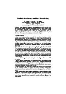
To build a complete Ethernet subsystem in an Altera device and connect it to an external device, you can use the LL Ethernet 10G MAC IP core with an Altera PHY IP core such as a soft XAUI PHY in FPGA fabric, hard silicon-integrated XAUI PHY, a 10GBASE-R PHY, a Backplane Ethernet 10GBASE-KR PHY, or a 1G/10 Gbps Ethernet PHY IP. ®
The following figure shows a system with the LL Ethernet 10G MAC core. Figure 1-1: Typical Application of LL Ethernet 10G MAC Altera FPGA XAUI or
10GbE MAC or Client Module
Avalon-ST Interface
1G/10GbE MAC or 10M/100M/ 1000M/10GbE MAC
XGMII/ GMII/MII
10GBASE-R or Backplane Ethernet 10GBASE-KR PHY or
Serial Interface
External PHY
1G/10Gbps Ethernet
Features The LL Ethernet 10G MAC supports the following features: • Operating modes: 10 Gbps, 1 Gbps/10 Gbps, or multi-speed (10 Mbps, 100 Mbps, 1 Gbps or 10 Gbps). • Available in the following variations: MAC Tx only block, MAC Rx only block, and MAC Tx and MAC Rx block. • Full duplex. • Client-side interface—32-bit Avalon-ST interface running at 312.5 MHz. © 2014 Altera Corporation. All rights reserved. ALTERA, ARRIA, CYCLONE, ENPIRION, MAX, MEGACORE, NIOS, QUARTUS and STRATIX words and logos are trademarks of Altera Corporation and registered in the U.S. Patent and Trademark Office and in other countries. All other words and logos identified as trademarks or service marks are the property of their respective holders as described at www.altera.com/common/legal.html. Altera warrants performance of its semiconductor products to current specifications in accordance with Altera's standard warranty, but reserves the right to make changes to any products and services at any time without notice. Altera assumes no responsibility or liability arising out of the application or use of any information, product, or service described herein except as expressly agreed to in writing by Altera. Altera customers are advised to obtain the latest version of device specifications before relying on any published information and before placing orders for products or services.
www.altera.com 101 Innovation Drive, San Jose, CA 95134
ISO 9001:2008 Registered
1-2
UG-01144 2014.06.30
Release Information
• PHY-side interface:
• • • • • • • • • • • • •
• 32-bit XGMII running at 312.5 MHZ. • 8-bit GMII running at 125 MHZ. • 4-bit MII running at 125 MHZ with clock enable; effective at 2.5 MHz for 10 Mbps and 25 MHz for 100 Mbps. Management interface—32-bit Avalon-MM interface. Virtual local area network (VLAN) and stacked VLAN tagged frames decoding as specified by IEEE 802.IQ and 802.1ad (Q-in-Q) standards respectively. Optional cyclic redundancy code (CRC)-32 computation and insertion on the transmit datapath. Optional CRC checking and forwarding on the receive datapath. Deficit idle counter (DIC) for optimized performance with average inter-packet gap (IPG) for LAN applications. Optional statistics collection on the transmit and receive datapaths. Programmable maximum length of transmit and receive data frames up to 64 Kbytes (KB). Programmable promiscuous (transparent) mode. Ethernet flow control using pause frames. Optional unidirectional feature as specified by IEEE 802.3 (Clause 66) Optional priority-based flow control (PFC) with programmable pause quanta. PFC supports up to 8 priority queues. Optional padding termination on the receive datapath and insertion on the transmit datapath. Optional preamble passthrough mode on the transmit and receive datapaths. The preamble passthrough mode allows you to define the preamble in the client frame. Optional IEEE 1588v2 feature for the following configurations: • 10GbE MAC with 10GBASE-R PHY IP core • 1G/10GbE MAC with 1G/10GbE PHY IP core • Multi-speed 10M-10GbE MAC with 10M-10GbE PHY IP core
Release Information The following table lists information about this release of the LL Ethernet 10G MAC IP core. Table 1-1: Release Information Item
Description
Version
14.0
Release Date
June 2014
Ordering Code
IP-10GEUMAC
Product ID
ID 0119
Vendor ID
6AF7
Altera verifies that the current version of the Quartus II software compiles the previous version of each MegaCore function, if this MegaCore function was included in the previous release. Any exceptions to
Altera Corporation
About this IP Core Send Feedback
UG-01144 2014.06.30
Device Family Support
1-3
this verification are reported in the MegaCore IP Library Release Notes and Errata. Altera does not verify compilation with MegaCore function versions older than the previous release. Related Information
• MegaCore IP Library Release Notes and Errata • Errata for Low Latency Ethernet 10G MAC MegaCore function in the Knowledge Base
Device Family Support MegaCore functions provide the following support for Altera device families: • Preliminary support—Altera verifies the IP core with preliminary timing models for this device family. The core meets all functional requirements, but might still be undergoing timing analysis for the device family. It can be used in production designs with caution. • Final support—Altera verifies the IP core with final timing models for this device family. The core meets all functional and timing requirements for the device family and can be used in production designs. Table 1-2: Device Family Support for LL Ethernet 10G MAC Device Family
Support
Arria 10
Preliminary
®
Arria V GZ
Final
Stratix V
Final
®
The following table lists the devices supported by the different configurations. Table 1-3: Device Family Support for Configurations Configuration
Arria V GZ
Arria 10
Stratix V
Multi-Speed 10M-10GbE MAC
Yes
Yes
Yes
Multi-Speed 10M-10GbE MAC with IEEE 1588v2
Yes
Yes
Yes
10GbE MAC with 10GBASE-R PHY
Yes
Yes
Yes
10GbE MAC with 10GBASE-R PHY and IEEE 1588v2
Yes
Yes
Yes
Multi-Speed 10M-10GbE MAC with Backplane Ethernet 10GBASE-KR PHY
Yes
Yes
Yes
Multi-Speed 10M-10GbE MAC with Backplane Ethernet 10GBASE-KR PHY and IEEE 1588v2
Yes
Yes
Yes
About this IP Core Send Feedback
Altera Corporation
1-4
UG-01144 2014.06.30
Performance and Resource Utilization
Performance and Resource Utilization The following estimates are obtained by compiling the LL Ethernet 10G MAC with the Quartus II software targeting a commercial Stratix V device. These data also apply to Arria V GZ and Arria 10 devices. Table 1-4: Performance and Resource Utilization for LL Ethernet 10G MAC Settings
Lowest Supported Speed Grade
ALMs
ALUTs
Logic Registers
Memory Block (M20K)
All options disabled
4
1,500
2,300
2,600
0
Memory-based statistics counters enabled. Other options disabled.
4
2,000
3,100
3,700
4
Multi-speed 10M-10GbE MAC. Memory-based statistics counters enabled. Other options disabled.
4
2,600
3,800
4,900
4
Multi-speed 10M-10GbE MAC. IEEE 1588v2 feature and memory-based statistics counters enabled. Other options disabled.
3
5,600
8,700
12,100
14
All options enabled except the adaptor.
3
6,800
10,400
14,300
21
Transmit and Receive Latencies Altera uses the following definitions for the transmit and receive latencies: • Transmit latency is the number of clock cycles the MAC function takes to transmit the first byte on the network-side interface (XGMII SDR) after the bit was first available on the Avalon-ST interface. • Receive latency is the number of clock cycles the MAC function takes to present the first byte on the Avalon-ST interface after the bit was received on the network-side interface (32-bit SDR XGMII).
Altera Corporation
About this IP Core Send Feedback
UG-01144 2014.06.30
Transmit and Receive Latencies
1-5
Table 1-5: Transmit and Receive Latencies of the LL Ethernet 10G MAC Latency (ns) (1) MAC Configuration
Transmit (with respect to TX clock)
Receive (with respect to RX clock)
Total
22.4
38.4
60.8
MAC with 10 Mbps mode
1,952.8
27,215.2
29,168
MAC with 100 Mbps mode
232.8
2,735.2
2,968
MAC with 1 Gbps mode (2)
79.2
277.6
356.8
MAC only
(1) (2)
The latency values are based on the assumption that there is no backpressure on the Avalon-ST TX and RX interface. The latency values for 1 Gbps mode is 360 ns under quad-speed mode.
About this IP Core Send Feedback
Altera Corporation
Getting Started
2
2014.06.30
UG-01144
Subscribe
Send Feedback
This chapter provides a general overview of the Altera IP core design flow to help you quickly get started with LL Ethernet 10G MAC. The Altera IP Library is installed as part of the Quartus II installation process. You can select and parameterize any Altera IP core from the library. Altera provides an integrated parameter editor that allows you to customize the MAC IP core to support a wide variety of applications. The parameter editor guides you through the setting of parameter values and selection of optional ports.
Introduction to Altera IP Cores Altera and strategic IP partners offer a broad portfolio of off-the-shelf, configurable IP cores optimized ® for Altera devices. Altera delivers an IP core library with the Quartus II software. OpenCore Plus IP evaluation enables fast acquisition, evaluation, and hardware testing of all Altera IP cores. ®
Nearly all complex FPGA designs include optimized logic from IP cores. You can integrate optimized and verified IP cores into your design to shorten design cycles and maximize performance. The Quartus II software includes the Altera IP Library, and supports IP cores from other sources. You can define and generate a custom IP variation to represent complex design logic in your project. The Altera IP Library includes the following IP core types: • • • • •
Basic functions DSP functions Interface protocols Memory interfaces and controllers Processors and peripherals
Related Information
IP User Guide Documentation
Installing and Licensing IP Cores The Quartus II software includes the Altera IP Library. The library provides many useful IP core functions for production use without additional license. You can fully evaluate any licensed Altera IP core in simulation and in hardware until you are satisfied with its functionality and performance. Some Altera © 2014 Altera Corporation. All rights reserved. ALTERA, ARRIA, CYCLONE, ENPIRION, MAX, MEGACORE, NIOS, QUARTUS and STRATIX words and logos are trademarks of Altera Corporation and registered in the U.S. Patent and Trademark Office and in other countries. All other words and logos identified as trademarks or service marks are the property of their respective holders as described at www.altera.com/common/legal.html. Altera warrants performance of its semiconductor products to current specifications in accordance with Altera's standard warranty, but reserves the right to make changes to any products and services at any time without notice. Altera assumes no responsibility or liability arising out of the application or use of any information, product, or service described herein except as expressly agreed to in writing by Altera. Altera customers are advised to obtain the latest version of device specifications before relying on any published information and before placing orders for products or services.
www.altera.com 101 Innovation Drive, San Jose, CA 95134
ISO 9001:2008 Registered
2-2
UG-01144 2014.06.30
Specifying IP Core Parameters and Options
IP cores, such as MegaCore functions, require that you purchase a separate license for production use. After you purchase a license, visit the Self Service Licensing Center to obtain a license number for any Altera product. ®
Figure 2-1: IP Core Installation Path
acds quartus - Contains the Quartus II software ip - Contains the Altera IP Library and third-party IP cores altera - Contains the Altera IP Library source code - Contains the IP core source files
Note: The default IP installation directory on Windows is :\altera\; on Linux it is /altera/ . Related Information
• Altera Licensing Site • Altera Software Installation and Licensing Manual
Specifying IP Core Parameters and Options Follow these steps to specify IP core parameters and options. 1. In the IP Catalog (Tools > IP Catalog), locate and double-click the name of the IP core to customize. The parameter editor appears. 2. Specify a top-level name for your custom IP variation. This name identifies the IP core variation files in your project. If prompted, also specify the target Altera device family and output file HDL preference. Click OK. 3. Specify parameters and options for your IP variation: • Optionally select preset parameter values. Presets specify all initial parameter values for specific applications (where provided). • Specify parameters defining the IP core functionality, port configurations, and device-specific features. • Specify options for generation of a timing netlist, simulation model, testbench, or example design (where applicable). • Specify options for processing the IP core files in other EDA tools. 4. Click Finish or Generate to generate synthesis and other optional files matching your IP variation specifications. The parameter editor generates the top-level .qip or .qsys IP variation file and HDL files for synthesis and simulation. Some IP cores also simultaneously generate a testbench or example design for hardware testing. 5. To generate a simulation testbench, click Generate > Generate Testbench System. Generate Testbench System is not available for some IP cores that do not provide a simulation testbench. 6. To generate a top-level HDL example for hardware verification, click Generate > HDL Example. Generate > HDL Example is not available for some IP cores.
Altera Corporation
Getting Started Send Feedback
UG-01144 2014.06.30
Parameterizing the IP Core
2-3
The top-level IP variation is added to the current Quartus II project. Click Project > Add/Remove Files in Project to manually add a .qip or .qsys file to a project. Make appropriate pin assignments to connect ports.
Parameterizing the IP Core To parameterize your IP core, follow these steps: 1. 2. 3. 4. 5.
Select the speed for the LL Ethernet 10G MAC IP. Turn on the necessary MAC Options. Type the number of PFC priorities. Select the datapath option. Turn on the necessary resource optimization options. Some options are grayed out if it is not supported in a selected configuration. 6. Turn on the necessary timestamp options. Some options are grayed out if it is not supported in a selected configuration. 7. Click Finish. Related Information
• Parameter Settings on page 2-3
Parameter Settings You customize the MAC IP core by specifying the parameters on the parameter editor in the Quartus II software. Parameter
Speed
Datapath option
Value
10 Gbps, 1 Gbps/10 Gbps, Multi-Speed 10 Mbps -10 Gbps
Description
Select the desired speed. By default, 10 Gbps is selected.
TX only, RX only, TX & Select the MAC variation to instantiate. RX • TX only—instantiates MAC TX. • RX only—instantiates MAC RX. • TX & RX—instantiates both MAC TX and RX.
Enable ECC on memory blocks
On, Off
Turn on this option to enable error detection and correction on memory blocks.
Enable Unidirectional feature
On, Off
Turn on this option to enable unidirectional feature as specified in the IEEE802.3 specifica‐ tion (Clause 66).
Getting Started Send Feedback
Altera Corporation
2-4
UG-01144 2014.06.30
Parameter Settings
Parameter
Enable preamble passthrough mode
Value
On, Off
Description
Turn on this option to enable preamble passthrough mode. You must also set the tx_ preamble_control, rx_preamble_control, and rx_custom_preamble_forward registers to 1. When enabled, the MAC IP core allows custom preamble in data frames on the transmit and receive datapaths. This parameter applies only to 10Gbps MAC variations.
Enable priority-based flow control (PFC)
On, Off
Turn on this option to enable PFC. You must also set the tx_pfc_priority_enable[n]bit to 1 and specify the number of priority queues in the Number of PFC queues field. This parameter applies only to 10Gbps MAC variations.
Number of PFC queues
2—8
Enable supplementary address
On, Off
Turn on this option to enable supplementary addresses. You must also set the EN_SUPP0/1/2/ 3 bits in the rx_frame_control register to 1.
Enable statistics collection
On, Off
Turn on this option to collect statistics on the transmit and receive datapaths.
Memory-based, Register-based
Specify the implementation of the statistics counters. When you turn on Statistics collection, the default implementation of the counters is Memory-based.
Statistics counters
Specify the number of PFC queues. This parameter is only enabled if you turn Enable priority-based flow control (PFC).
• Memory-based—selecting this option frees up logic elements. The MAC IP core does not clear memory-based counters after they are read. • Register-based—selecting this option frees up the memory. The MAC IP core clears register-based statistic counters after the counters are read. Enable time stamping
On, Off
Turn on this option to enable time stamping on the transmit and receive datapaths.
Enable PTP 1-step clock support
On, Off
Turn on this option to enable 1-step time stamping. This option is enabled only when you turn on time stamping.
Altera Corporation
Getting Started Send Feedback
UG-01144 2014.06.30
Generated Files
Parameter
Timestamp fingerprint width
Value
1–32
2-5
Description
Specify the width of the timestamp fingerprint in bits on the transmit path. The default value is 4 bits.
Use 64-bit Ethernet 10G MAC XGMII
On, Off
Turn on this option to maintain compability with the 64-bit Ethernet 10G MAC on the XGMII.
Use 64-bit Ethernet 10G MAC Avalon MemoryMapped Interface
On, Off
Turn on this option to maintain compability with the 64-bit Ethernet 10G MAC on the Avalon-MM Interface.
Use 64-bit Ethernet 10G MAC Avalon Streaming Interface
On, Off
Turn on this option to maintain compability with the 64-bit Ethernet 10G MAC on the Avalon-ST interface.
Generated Files The following table describes the generated files and other files that might be in your project directory. The names and types of generated files specified in the MegaWizard Plug-In Manager report vary depending on whether you create your design with VHDL or Verilog HDL. Table 2-1: Generated Files Extension
Description
.v or .vhd A MegaCore function variation file, which defines a VHDL or Verilog HDL description of the custom MegaCore function. Instantiate the entity defined by this file inside of your design. Include this file when compiling your design in the Quartus II software. .cmp
A VHDL component declaration file for the MegaCore function variation. Add the contents of this file to any VHDL architecture that instantiates the MegaCore function.
.qsys
A Qsys file for the MAC IP core design.
.qip
Contains Quartus II project information for your MegaCore function variation.
.bsf
Quartus II symbol file for the MegaCore function variation. Use this file in the Quartus II block diagram editor.
.sip
Contains IP core library mapping information required by the Quartus II software.The Quartus II software generates a . sip file during generation of some Altera IP cores. You must add any generated .sip file to your project for use by NativeLink simulation and the Quartus II Archiver.
.spd
Contains a list of required simulation files for your MegaCore function.
Getting Started Send Feedback
Altera Corporation
2-6
UG-01144 2014.06.30
Simulating Altera IP Cores in other EDA Tools
Simulating Altera IP Cores in other EDA Tools The Quartus II software supports RTL- and gate-level design simulation of Altera IP cores in supported EDA simulators. Simulation involves setting up your simulator working environment, compiling simulation model libraries, and running your simulation. You can use the functional simulation model and the testbench or example design generated with your IP core for simulation. The functional simulation model and testbench files are generated in a project subdirectory. This directory may also include scripts to compile and run the testbench. For a complete list of models or libraries required to simulate your IP core, refer to the scripts generated with the testbench. You can use the Quartus II NativeLink feature to automatically generate simulation files and scripts. NativeLink launches your preferred simulator from within the Quartus II software. Figure 2-2: Simulation in Quartus II Design Flow Design Entry (HDL, Qsys, DSP Builder)
Altera Simulation Models
Quartus II Design Flow
Gate-Level Simulation
Analysis & Synthesis
Fitter (place-and-route)
TimeQuest Timing Analyzer
RTL Simulation
EDA Netlist Writer
Post-synthesis functional simulation netlist
Post-synthesis functional simulation
Post-fit functional simulation netlist
Post-fit functional simulation
Post-fit timing simulation netlist
(Optional) Post-fit Post-fit timing timing simulation simulation (3)
Device Programmer
Note: Altera IP supports a variety of simulation models, including simulation-specific IP functional simulation models and encrypted RTL models, and plain text RTL models. These are all cycle-accurate models. The models support fast functional simulation of your IP core instance using industry-standard VHDL or Verilog HDL simulators. For some cores, only the plain text RTL model is generated, and you can simulate that model. Use the simulation models only for simulation and not for synthesis or any other purposes. Using these models for synthesis creates a nonfunctional design. Related Information
Simulating Altera Designs
Altera Corporation
Getting Started Send Feedback
UG-01144 2014.06.30
Migrating from Ethernet 10G MAC to LL Ethernet 10G MAC
2-7
Migrating from Ethernet 10G MAC to LL Ethernet 10G MAC Altera recommends the following migration path. Migrating your existing design in this manner allows you to take advantage of the benefits of LL Ethernet 10G MAC—low resource count and low latency.
Migration—32-bit Datapath on Avalon-ST This migration path implements 32-bit datapath on the Avalon ST transmit and receive data interfaces and configuration and status registers of LL Ethernet 10G MAC. 1. Instantiate the LL Ethernet 10G MAC IP core in your design. If you are using 64-bit PHY, turn on the Use 64-bit Ethernet 10G MAC XGMII option. 2. Modify your user logic to accommodate 32-bit datapath on both Avalon-ST transmit and receive data interfaces. 3. Change the clock source to the MAC IP core to 312.5 MHz. 4. Update existing register offsets to the register offsets of the LL Ethernet 10G MAC. Using the configu‐ ration and status registers of the LL Ethernet 10G MAC allows access to features implemented using registers such as error correction and detection on memory blocks. 5. For 64-bit PHY, add a 156.25 MHz clock source for the 32-bit/64-bit adapter. This 156.25 MHz clock source must be synchronous with the 312.5 MHz clock source.
Migration—Maintains 64-bit on Avalon-ST This migration path implements 32-bit to 64-bit adapters on the Avalon ST transmit and receive data interfaces and XGMII, and uses the same register offsets to maintain compatibility with the Ethernet 10G MAC IP Core. 1. Instantiate the LL Ethernet 10G MAC IP core in your design. To maintain compatibility on the interfaces, turn on the Use 64-bit Ethernet 10G MAC XGMII, Use 64-bit Ethernet 10G MAC Avalon Memory-Mapped Interface, and Use 64-bit Ethernet 10G MAC Avalon Streaming Interface options. 2. Change the clock source to the MAC IP core to 312.5 MHz. 3. Add 156.25 MHz clock source for the 32-bit/64-bit adapters. This 156.25 MHz clock source must be synchronous with the 312.5 MHz clock source.
Upgrading Outdated IP Cores Altera IP components are version-specific with the Quartus II software. The Quartus II software alerts you when your IP core is outdated. Click Project > Upgrade IP Components to easily identify and upgrade outdated IP cores. To upgrade outdated IP cores appropriately, your restored project archive must retain the original Quartus II-generated file structure. Failure to upgrade outdated IP cores can result in a mismatch between the outdated IP core variation and the current supporting libraries. Altera verifies that the current version of the Quartus II software compiles the previous version of each IP core. The MegaCore IP Library Release Notes and Errata reports any verification exceptions. Altera does not verify compilation for IP cores older than the previous release.
Getting Started Send Feedback
Altera Corporation
2-8
Migrating Outdated IP Cores
UG-01144 2014.06.30
Figure 2-3: Upgrading IP Components in Project Navigator
Related Information
MegaCore IP Library Release Notes and Errata
Migrating Outdated IP Cores To migrate outdated IP cores for use in Arria 10 designs, follow these steps: 1. In the latest version of the Quartus II software, open the Quartus II project containing the outdated original IP core variation. 2. Click Project > Upgrade IP Components. 3. Double-click your IP core variation that requires migration. The parameter editor appears. 4. Under Currently selected device family, disable Match project/default and select Arria 10. The parameter editor displays information about incompatible parameters between the old and new versions of the IP core. Modify any incompatible parameters until all error messages are resolved. 5. Click Finish to save parameters and launch the parameter editor for the latest version of the IP core. The parameter editor displays information about incompatible parameters between the old and new versions of the IP core. Modify any incompatible parameters until all error messages are resolved. 6. Click Generate to generate the latest version of IP core synthesis and simulation files matching your specifications for Arria 10 designs. Click Finish to complete the migration process. The new top-level .qip IP variation file is added to the project. Project subdirectories now contain HDL files for synthesis and simulation in the Quartus II software and other supported EDA tools. Your IP core variation is suitable for use in Arria 10 designs.
Altera Corporation
Getting Started Send Feedback
UG-01144 2014.06.30
Migrating Outdated IP Cores
2-9
Figure 2-4: Upgrade IP Components GUI
Note: Port names between different IP core versions may not match. Therefore, simply changing the instantiation of IP name instantiation insufficient for migration.
Getting Started Send Feedback
Altera Corporation
3
Functional Description 2014.06.30
UG-01144
Subscribe
Send Feedback
The Low Latency (LL) Ethernet 10G MAC IP core handles the flow of data between a client and an Ethernet network through an Ethernet PHY. On the transmit path, the MAC IP core accepts client frames and constructs Ethernet frames by inserting various control fields, such as checksums before forwarding them to the PHY. Similarly, on the receive path, the MAC accepts Ethernet frames via a PHY, performs checks, and removes the relevant fields before forwarding the frames to the client. You can configure the MAC IP core to collect statistics on both transmit and receive paths. This chapter describes the MAC IP core, its architecture, interfaces, data paths, registers, and interface signals.
Architecture The LL Ethernet 10G MAC IP core is a composition of the following blocks: MAC receiver (MAC RX), MAC transmitter (MAC TX), configuration and status registers, and clock and reset. Figure 3-1: LL Ethernet 10G MAC Block Diagram
32-Bit Avalon-ST Transmit Interface
32-Bit Avalon-MM Interface
32-Bit Avalon-ST Receive Interface
LL Ethernet 10G MAC MAC TX
Control & Status Registers
Flow Control
32-Bit XGMII Transmit Interface 8-Bit GMII Transmit Interface 4-Bit MII Transmit Interface
(1) (2)
32-Bit XGMII Receive Interface 8-Bit GMII Receive Interface 4-Bit MII Receive Interface
(1) (2)
Link Fault
MAC RX Respective Domains Clock & Reset Clock & Reset Signals
Notes: (1) Applies to 1G/10G and Multi Speed MAC only. (2) Applies to Multi Speed MAC only.
© 2014 Altera Corporation. All rights reserved. ALTERA, ARRIA, CYCLONE, ENPIRION, MAX, MEGACORE, NIOS, QUARTUS and STRATIX words and logos are trademarks of Altera Corporation and registered in the U.S. Patent and Trademark Office and in other countries. All other words and logos identified as trademarks or service marks are the property of their respective holders as described at www.altera.com/common/legal.html. Altera warrants performance of its semiconductor products to current specifications in accordance with Altera's standard warranty, but reserves the right to make changes to any products and services at any time without notice. Altera assumes no responsibility or liability arising out of the application or use of any information, product, or service described herein except as expressly agreed to in writing by Altera. Altera customers are advised to obtain the latest version of device specifications before relying on any published information and before placing orders for products or services.
www.altera.com 101 Innovation Drive, San Jose, CA 95134
ISO 9001:2008 Registered
3-2
UG-01144 2014.06.30
Interfaces
Interfaces Table 3-1: Interfaces Interfaces
Avalon-ST Interface
Description
The client-side interface of the MAC employs the Avalon-ST protocol, which is a synchronous point-to-point, unidirectional interface that connects the producer of a data stream (source) to a consumer of the data (sink). The key properties of this interface include: • Frame transfers marked by startofpacket and endofpacket signals. • Signals from source to sink are qualified by the valid signal. • Errors marking a current packet are aligned with the end-ofpacket cycle. • Use of the ready signal by the sink to backpressure the source. In the MAC IP core, the Avalon-ST interface acts as a sink in the transmit datapath and source in the receive datapath. These 32-bit interfaces operate at 312.5 and support packets, backpressure, and error. The ready latency on these interfaces is 0.
Avalon-MM Control and Status Register Interface
The Avalon-MM control and status register interface is an Avalon-MM slave port. This interface uses word addressing which provides host access to 32-bit configuration and status registers, and statistics counters.
XGMII
When you configure the MAC IP core to operate in 10-Gbps mode, the network-side interface of the MAC IP core implements the XGMII protocol. The XGMII consists of 32-bit data bus and 4bit control bus operating at 312.5 MHz. The data bus carries the MAC frame with the most significant byte occupying the least significant lane.
GMII
When you configure the MAC IP core to operate in 1-Gbps, the network-side interface of the MAC IP core also implements the GMII protocol. This 8-bit interface supports gigabit operations at 125 MHz.
MII
When you configure the MAC IP core to operate in 10 Mbps or 100 Mbps, the network-side interface of the MAC IP core implements the MII protocol. This 4-bit MII supports 10-Mbps and 100-Mbps operations at 125 MHz, with a clock enable signal that divides the clock to effective rates of 2.5 MHz for 10 Mbps and 25 MHz for 100 Mbps.
Altera Corporation
Functional Description Send Feedback
UG-01144 2014.06.30
Interfaces
3-3
Figure 3-2: Interface Signals LL Ethernet 10G MAC
Avalon-ST Transmit Data Interface
Avalon-ST Transmit Flow Control Interface
Avalon-ST Transmit Status Interface
Avalon-ST Receive Data Interface
Avalon-ST Receive Flow Control Interface
Avalon-ST Receive Status Interface
Avalon-MM Control and Status Interface
MAC TX
avalon_st_tx_startofpacket avalon_st_tx_endofpacket avalon_st_tx_valid avalon_st_tx_ready avalon_st_tx_error avalon_st_tx_data[31:0] avalon_st_tx_empty[1:0]
xgmii_tx_data[35:0] link_fault_status_xgmii_tx_data[1:0] gmii_tx_clk gmii_tx_d[7:0] gmii_tx_en gmii_tx_err tx_clkena tx_clkena_half_rate mii_tx_d[3:0] mii_tx_en mii_tx_err
avalon_st_pause_data[1:0] avalon_st_tx_pause_length_valid avalon_st_tx_pause_length_data[15:0] avalon_st_tx_pfc_gen_data[n] avalon_st_txstatus_valid avalon_st_txstatus_data[39:0] avalon_st_txstatus_error[6:0] avalon_st_tx_pfc_status_valid avalon_st_tx_pfc_status_data[n]
tx_egress_timestamp_request_valid tx_egress_timestamp_request_fingerprint[n]
xgmii_rx_data[35:0] link_fault_status_xgmii_rx_data[1:0] gmii_rx_clk gmii_rx_d[7:0] gmii_rx_dv gmii_rx_err
avalon_st_rx_pause_length_valid avalon_st_rx_pfc_pause_data[n] avalon_st_rx_pause_length_data[15:0]
avalon_st_rxstatus_valid avalon_st_rxstatus_data[39:0] avalon_st_rxstatus_error[6:0] avalon_st_rx_pfc_status_valid avalon_st_rx_pfc_status_data[n] csr_read csr_readdata[31:0] csr_write csr_writedata[31:0] csr_address[12:0] csr_waitrequest
GMII Transmit (1G/10Gbps, multi-speed)
MII Transmit (multi-speed)
IEEE 1588v2 Interface
tx_path_delay_10g_data[15:0]
MAC RX
avalon_st_rx_startofpacket avalon_st_rx_endofpacket avalon_st_rx_valid avalon_st_rx_ready avalon_st_rx_error[5:0] avalon_st_rx_data[31:0] avalon_st_rx_empty[1:0]
XGMII Transmit
rx_clkena rx_clkena_half_rate mii_rx_d[3:0] mii_rx_dv mii_rx_err rx_ingress_timestamp_96b_data[95:0] rx_ingress_timestamp_96b_valid rx_path_delay_10g_data[15:0]
Avalon-MM
XGMII Receive GMII Receive (1G/10Gbps, multi-speed)
MII Receive (multi-speed) IEEE 1588v2 Time-Stamp Interface
speed_sel ecc_err_det_corr ecc_err_det_uncorr unidirectional_en unidirectional_remote_fault_dis
Control and Reset Clock and Reset
csr_clk csr_rst_n tx_312_5_clk tx_156_25_clk
tx_rst_n rx_312_5_clk rx_156_25_clk rx_rst_n
Related Information
Interface Signals on page 5-1 Describes each signal in detail.
Functional Description Send Feedback
Altera Corporation
3-4
UG-01144 2014.06.30
Frame Types
Frame Types The MAC IP core supports the following frame types: • Basic Ethernet frames, including jumbo frames. • VLAN and stacked VLAN frames. • Control frames, which include pause and PFC frames.
Transmit Datapath The MAC TX receives the client payload data with the destination and source addresses, and appends various control fields depending on the MAC configuration. Figure 3-3: Typical Client Frame at Transmit Interface
Client-Defined Preamble [63:0] (optional) MAC Frame Preamble [55:0]
SFD[7:0]
Client Frame Destination Addr[47:0]
Source Addr[47:0]
Type/ Length[15:0]
Client - MAC Tx Interface Destination Addr[47:0]
Source Addr[47:0]
Type/ Length[15:0]
Payload (1) PAD [] (2) CRC32 [:0] [31:0] (optional)
Payload [:0]
PAD []
CRC32 [31:0]
EFD[7:0]
IPG (3) [:0]
Frame Length
Padding Bytes Insertion By default, the MAC TX inserts padding bytes (0x00) into transmit frames to meet the following minimum payload length: • 46 bytes for basic frames • 42 bytes for VLAN tagged frames • 38 bytes for stacked VLAN tagged frames Ensure that CRC-32 insertion is enabled when padding bytes insertion is enabled. You can disable padding bytes insertion by setting the tx_pad_control register to 0. When disabled, the MAC IP core forwards the frames to the PHY-side interface without padding. Ensure that the minimum payload length is met; otherwise the current frame may get corrupted. You can check for undersized frames by referring to the statistics collected.
Address Insertion By default, the MAC TX retains the source address received from the client. You can configure the MAC TX to replace the source address with the primary MAC address specified in the tx_addrins_macaddr0 and tx_addrins_macaddr1 registers by setting the bit tx_src_addr_override[0] to 1.
Altera Corporation
Functional Description Send Feedback
UG-01144 2014.06.30
CRC-32 Insertion
3-5
CRC-32 Insertion By default, the MAC TX computes and inserts CRC-32 checksum into transmit frames. The MAC TX computes the CRC-32 checksum over frame bytes that include the source address, destination address, length, data, and padding bytes. The computation excludes the preamble and SFD bytes. The MAC TX then inserts the CRC-32 checksum into the transmit frame. Bit 31st of the checksum occupies the least significant bit of the first byte in the CRC field. You can disable this function by setting the tx_crc_control[1] register bit to 0. The following figure shows the timing diagram on the Avalon-ST data interfaces where CRC insertion is enabled on transmit and CRC removal is disabled on receive. The frame from the client is without CRC-32 checksum. The MAC TX inserts the CRC-32 checksum (4EB00AF4) into the frame. The frame is then looped back to the receive datapath with the CRC-32 checksum. Figure 3-4: Avalon-ST Transmit and Receive Interface with CRC Insertion Enabled
tx_312_5_clk avalon_st_tx_ready avalon_st_tx_valid avalon_st_tx_startofpacket avalon_st_tx_endofpacket ...00000000
avalon_st_tx_data[31:0] avalon_st_tx_empty[1:0]
0
avalon_st_tx_error
rx_312_5_clk avalon_st_rx_ready avalon_st_rx_valid avalon_st_rx_startofpacket avalon_st_rx_endofpacket avalon_st_rx_data[31:0] avalon_st_rx_empty[1:0]
...4EB30AF4
0
avalon_st_rx_error[5:0]
Functional Description Send Feedback
Altera Corporation
3-6
UG-01144 2014.06.30
XGMII Encapsulation
The following figure shows the timing diagram on the Avalon-ST data interfaces where CRC insertion is disabled on transmit and CRC removal is disabled on receive. The MAC TX receives the frame from the client with a CRC-32 checksum (4EB00AF4). The frame with the same CRC-32 checksum is then looped back to the receive datapath. Figure 3-5: Avalon-ST Transmit and Receive Interface with CRC Insertion Disabled
tx_312_5_clk avalon_st_tx_ready avalon_st_tx_valid avalon_st_tx_startofpacket avalon_st_tx_endofpacket ...4EB30AF4
avalon_st_tx_data[31:0] avalon_st_tx_empty[1:0]
0
avalon_st_tx_error
rx_312_5_clk avalon_st_rx_ready avalon_st_rx_valid avalon_st_rx_startofpacket avalon_st_rx_endofpacket avalon_st_rx_data[31:0] avalon_st_rx_empty[1:0]
...4EB30AF4
0
avalon_st_rx_error[5:0]
XGMII Encapsulation By default, the MAC TX inserts 7-byte preamble, 1-byte SFD and 1-byte EFD (0xFD) into frames received from the client. The MAC TX also supports custom preamble. To use custom preamble, set the tx_preamble_control register to 1. In this mode, the MAC TX accepts the first 8 bytes in the frame from the client as custom preamble and inserts only 1-byte EFD (0xFD) into the frame. The MAC TX also replaces the first byte of the preamble with 1-byte START (0xFB). Altera Corporation
Functional Description Send Feedback
UG-01144 2014.06.30
Inter-Packet Gap Generation and Insertion
3-7
An underflow could occur on the Avalon-ST transmit interface. An underflow occurs when the avalon_st_tx_valid signal is deasserted in the middle of frame transmission. When this happens, the 10GbE MAC TX inserts an error character |E| into the frame and forwards the frame to the XGMII.
Inter-Packet Gap Generation and Insertion The MAC TX maintains an average IPG between transmit frames as required by the IEEE 802.3 Ethernet standard. The average IPG is maintained at 96 bit times (12 byte times) using the deficit idle count (DIC). The MAC TX's decision to insert or delete idle bytes depends on the value of the DIC; the DIC is bounded between a value of nine to fifteen bytes. Averaging the IPG ensures that the MAC utilizes the maximum available bandwidth.
XGMII Transmission On the XGMII, the MAC TX performs the following: • Aligns the first byte of the frame to lane 0 of the interface. • Performs endian conversion. Transmit frames received from the client on the Avalon-ST interface are big endian. Frames transmitted on the XGMII are little endian; the MAC TX therefore transmits frames on this interface from the least significant byte. The following figure shows the timing on the Avalon-ST transmit data interface and XGMII. The least significant byte of the value in D5 is transmitted first on the XGMII.
Functional Description Send Feedback
Altera Corporation
3-8
UG-01144 2014.06.30
Unidirectional Feature
Figure 3-6: Endian Conversion Data value: tx_312_5_clk
D1: 555555D5 D2: EECC88CC D3: AAEEEECC
avalon_st_tx_ready
D4: 88CCAAEE
avalon_st_tx_valid
D5: 002E0001 D6: 02030405
avalon_st_tx_startofpacket
D7: 06070809 D8: 0A0B0C0D
avalon_st_tx_endofpacket D1
avalon_st_tx_data[31:0]
D2
D3
D4
D5
D6
D7
0
avalon_st_tx_empty[1:0]
D8
D9 D10 D11 D12 D13 D14 D15 D16 D17
4
0
D9: 0E0F1011 D10: 12131415 D11: 16171819
4
D12: 1A1B1C1D avalon_st_tx_error
D13: 1E1F2021 D14: 22232425 D15: 26272829 D16: 2A2B2C2D D17: 4EB30AF4
tx_312_5_clk xgmii_tx_control[3] xgmii_tx_data[31:24]
55 (1) D5
CC
CC
EE
01
05
09
0D
11
15
19
1D
21
25
29
2D
F4
07
55(1) 55
88
EE
AA
00
04
08
0C
10
14
18
1C
20
24
28
2C
0A
07
55(1) 55
CC
EE
CC
2E
03
07
0B
0F
13
17
1B
1F
23
27
2B
B3
07
FB
EE
AA
88
00
02
06
0A
0E
12
16
1A
1E
22
26
2A
4E
FD
xgmii_tx_control[2] xgmii_tx_data[23:16] xgmii_tx_control[1] xgmii_tx_data[15:8] xgmii_tx_control[0] xgmii_tx_data[7:0]
55
07
Unidirectional Feature The unidirectional feature is an option that you can enable on the TX datapath. This feature is implemented as specified in the IEEE802.3 specification, Clause 66. When you enable this feature, two output ports—unidirectional_en, unidirectional_remote_fault_dis— and two register fields—UniDir_En (Bit 0), UniDirRmtFault_Dis (Bit 1)— are accessible to control the TX XGMII interface.
Altera Corporation
Functional Description Send Feedback
UG-01144 2014.06.30
3-9
TX Timing Diagrams
Table 3-2: Register Field and Link Status Bit 0 Register Field
Bit 1 Register Field
Link Status
TX XGMII Interface Behaviour
Don't care
Don't care
No link fault
Continue to allow normal packet transmission.
0
Don't care
Local fault
Immediately override the current content with remote fault sequence.
1
0
Local fault
Continue to send packet if there is one. Otherwise, override the IPG/IDLE bytes with remote fault sequence.(3)
1
1
Local fault
Continue to allow normal packet transmission (similar to no link fault).
0
Don't care
Remote fault
Immediately override the current content with IDLE control characters.
1
Don't care
Remote fault
Continue to allow normal packet transmission (similar to no link fault).
TX Timing Diagrams Figure 3-7: Normal Frame The following diagram shows the transmission of a normal frame. tx_312_5_clk avalon_st_tx_startofpacket avalon_st_tx_valid avalon_st_tx_ready avalon_st_tx_endofpacket avalon_st_tx_error avalon_st_tx_empty[1:0] avalon_st_tx_data[31:0] xgmii_tx_data[31:0] xgmii_tx_control[3:0] avalon_st_tx_data[31:24] avalon_st_tx_data[23:16] avalon_st_tx_data[15:8] avalon_st_tx_data[7:0] xgmii_tx_data[7:0] xgmii_tx_data[15:8] xgmii_tx_data[23:16] xgmii_tx_data[31:24]
(3)
0 0f8e_8236
0023_4567
0707_0707 f
3
0
*5 *1 *2 *2 *5 *b *c *7 *e *d *5 *3 *e *5 *0
cc6b_d355
*b *5 *0 *9 *1 *0 *c *e *b *6 *1 *0 *b *7 *6 *d *d *d *2 1
0
0707_0707
e
f
0f 8e
00 23
89 f1 00 fc ce 6b 26 01 e0 0b 87 a6 7d 4d 5d ab c7 2f 8c 3f 9f d9 77 59 71 e5 3a 42 00
cc 6b
82 36
45 67
c4 e9 fb 00 62 f7 80 84 09 c5 21 65 4b b1 00 d5 61 d2 82 85 4b fc 67 9e 9d 45 23 ee a5 00
d3 55
07
fb 55 00 89 f1 00 fc ce 6b 26 01 e0 0b 87 a6 7d 4d 5d a2
07
3a 42 13 fd
07
07
55 23 ab c7 2f 8c 3f 9f d9 77 59 71
07
55 45 c4 e9 fb 00 62 f7 80 84 09 c5 21 65 4b b1 8a
07
07
55 d5 67 d5 61 d2 82 85 4b fc 67 9e 8d 45 23 ee a5 d0
07
e5
At least a full column of IDLE (four IDLE characters) must precede the remote fault sequence.
Functional Description Send Feedback
Altera Corporation
3-10
UG-01144 2014.06.30
TX Timing Diagrams
Figure 3-8: Normal Frame with Preamble Passthrough Mode, Padding Bytes Insertion, and Source Address Insertion Enabled The following diagram shows the transmission of good frames with preamble passthrough mode, padding bytes insertion, and source address insertion enabled. tx_312_5_clk avalon_st_tx_startofpacket avalon_st_tx_valid avalon_st_tx_ready avalon_st_tx_endofpacket avalon_st_tx_error avalon_st_tx_empty[1:0] avalon_st_tx_data[31:0] xgmii_tx_data[31:0] xgmii_tx_control[3:0]
0 0 3 0faa_4s5e *5 *_fff *fb *4 *5 *3 *f *0 *9 *a *1 *3 *0 *3 *0 7c91_5b8d *b *1 *_fff *ff *2 *0 *b *0 *e *5 *5 *6 *3 *0 *4 *c *0 *8 *d 0707_0707 0 f 1
92e6_9b29
avalon_st_tx_data[31:24] avalon_st_tx_data[23:16] avalon_st_tx_data[15:8] avalon_st_tx_data[7:0]
92 e6 9b 29
0f aa 4a 5e
xgmii_tx_data[7:0] xgmii_tx_data[15:8] xgmii_tx_data[23:16] xgmii_tx_data[31:24]
d1 bf 83 d5
ff ff ff 44 ff fb
2b 00 5b 98 2f 5d 1d 45 e3 24 f5 f3
60 8e 65 de 4b 4e 5b 09 bb 2f 20 69
25 36 13 54 53 13 db 10 e8 ba 21 53
fb d1 *5 *5 *5 *5 *5 *5
07 07 07 07
10 04 60 a1 00 86 a9 00 f0 83 00
ff 22 00 ff 33 2f ff 00 44 45 ff 00 55 f5
0707_0707 f
7c 81 5b 8d
5b 60 8e 5d de 4b e3 5b 09 f3 2f 20
65 25 36 4e 54 53 bb db 10 69 ba 21
13 10 04 13 60 a1 e8 86 a9 53 f0 83
7c 00 00 00 00
38 fd 7a 9c ee
07 07 07 07
Figure 3-9: Back-to-back Transmission of Normal Frames with Source Address Insertion Enabled. The following diagram shows back-to-back transmission of normal frames with source address insertion enabled. The MAC primary address registers are set to 0x000022334455. tx_312_5_clk avalon_st_tx_startofpacket avalon_st_tx_valid avalon_st_tx_ready avalon_st_tx_endofpacket avalon_st_tx_error avalon_st_tx_empty[1:0] avalon_st_tx_data[31:0] xgmii_tx_data[31:0] xgmii_tx_control[3:0] avalon_st_tx_data[31:24] avalon_st_tx_data[23:16] avalon_st_tx_data[15:8] avalon_st_tx_data[7:0] xgmii_tx_data[7:0] xgmii_tx_data[15:8] xgmii_tx_data[23:16] xgmii_tx_data[31:24]
Altera Corporation
0
0
3
8190_a0b0 *a7 *8d *ed *05 *56 *f0 *d6 *44 *95 *f4 *38 *03 *31 *0b *7a *00 *0_a0b0 *d2 *96 *01 *5c *43 *cb *e3 0707_0707 f
b4c1_cafd
*f0 *4c 0023_456
*fb *55 *81 *c0 *22 *3d *f5 *08 *d6 *7e *51 *37 *1a *95 *a2 *9f *96 *b9 *e3 *be *7_0707 *fb *55 *81 *c0 *22 1
0
e
f
1
0
81
c0 15 3d f5 08 d6 7e 51 37 1a 95 a2 31 96 b9 e3
81
c0 d6 88 00 7b 31 0e
b4
49 25
00
90
d0 83 61 1c 75 e3 f4
99 cd bc 83 85 5a 00
90
d0 07 08 0a 40 9f 76
c1
04 8b
23
a0
e7 35 1b 2f ff 5a b1 fc 06 b2 a8 ca 54 0d 4f 00
a0
cd 39 00 1d 05 11 57
ca
e1 27
45
b0
a7 8d ed 05 56 f0 d6 44 95 f4 38 ca 31 0b 7a 00
b0
d2 96 01 5c 43 cb e3
fd
f0 4c
67
07
7b
fb 55 81 c0 22 3d f5 08 d6 7e 51 37 1a 95 a2 9f 96 b9 e3 be 55
90 d0 33 61 1c 75 e3 f4
07
55
a0 00 44 1b 2f ff 5a b1 fc 06 b2 a8 ca 54 0d 4f 53
07
55 d5 b0 00 55 ed 05 56 f0 d6 44 95 f4 38 03 31 0b 7a 88
07
07
7b
99 cd bc 83 85 5a c7 fd
07
07
07
fb 55 81 c0 22 55
90 d0 33
55
a0 00 44
55 d5 b0 00 55
Functional Description Send Feedback
UG-01144 2014.06.30
3-11
TX Timing Diagrams
Figure 3-10: Back-to-back Transmission of Normal Frames with Preamble Passthrough Mode Enabled The following diagram shows back-to-back transmission of normal frames with preamble passthrough mode enabled. tx_312_5_clk avalon_st_tx_startofpacket avalon_st_tx_valid avalon_st_tx_ready avalon_st_tx_endofpacket avalon_st_tx_error avalon_st_tx_empty[1:0] avalon_st_tx_data[31:0] xgmii_tx_data[31:0] xgmii_tx_control[3:0] avalon_st_tx_data[31:24] avalon_st_tx_data[23:16] avalon_st_tx_data[15:8] avalon_st_tx_data[7:0] xgmii_tx_data[7:0] xgmii_tx_data[15:8] xgmii_tx_data[23:16] xgmii_tx_data[31:24]
* * * * * * * * * * *3 * ac8b_600d * * * * * * * * * * * * * * * * * * * * * * * * * * * * * * *
* * * * * aa2f_4bbd * * *
* * * * * * * * * * * * * * * *707 *b * * * * * *0 * * * * * * * * * * * * * * * * * * * * * * *
* * * * * * *b * *707 * *
0
f
1
0
e
f
1 0
6f de b3 23 32 5f 00 89 3b a5 00 0b
ac
71 a0 90 c9 4c f0 6c 61 a4 7a f9 36 22 1a 21 b7 f3 a3 bc 84 69 30 fa 2e a9 87 bb f5 db b5 22
ff 64 00 67 4d
aa
ea 2c c8
2b d2 b4 5f 1f 37 23 ab 05 1b ff 7e
8b
d3 bc 59 b0 db 15 ae e2 ad 04 02 0f 21 62 74 c0 36 f9 c8 13 d9 12 15 f0 a4 da 00 45 37
ff bd ac 03 53
2f
81 4b e7
f8 25 d4 48 e9 ad a5 45 f0 e3 8f b7 fa
60
da d7 38 0f a9 60 be 4d 34 0d 83 d4 68 5d 8c e0 6e eb e7 c1 26 74 95 65 ac ce 79 00 85 8a ff 03 5d 3b f5 ba
4b
97 eb 24
89 8d 93 66 3a d5 67 62 94 f3 9c
0d
ee 3f 2c 44 d5 ca 11 85 6c 57 4e 7b 26 64 5e 48 d8 bc 03 0a e7 0a 19 a4 5c 9e b0 4a 00 40 d5 ff 22 5b 50 a8 83
bd
94 ce 48
fe 8d ad 56 98 fb 8f b3 50 6f de b3 23 4a fd 07 fb 5f 00 89 3b a5 00 0b ac 71 a0 90 c9 4c f0 6c 61 a4 7a f9 30 22 1a 21 b7 f3 a3 bc 84 69 30 fa 2e a9 87 bb f5 db 7e 07 fb 22 8d b9 81 16 88 54 ac fc b3 2b d2 b4 5f a6
07
1f 37 23 ab 05 1b ff 7e 8b d3 bc 59 b0 db 15 ae e2 ad 04 02 0f 21 62 74 c0 36 f9 c8 13 d9 12 15 f0 a4 da f4 fd 07 45 37
2b 0f 49 ca 38 40 9f 14 f8 25 d4 48 e9 0a
07
ad a5 45 f0 e3 8f b7 fa 60 da d7 38 0f a9 60 be 4d 34 0d 83 d4 68 5d 8c e0 6e eb e7 c1 26 74 95 65 ac ce 79 0f
07
85 8a
d6 38 84 f0 3a 76 7f 9c c5 89 8d 93 66 e7
07
3a d5 67 62 94 f3 9c 0d ee 3f 2c 44 d5 ca 11 85 6c 57 4e 7b 26 64 5e 48 d8 bc 03 0a e7 0a 19 a4 5c 9e b0 4a ce
07
40 d5
Figure 3-11: Error Condition—Underflow The following diagrams show an underflow on the transmit datapath followed by the transmission of a normal frame. pulse_tx_udf_errcnt tx_312_5_clk avalon_st_tx_startofpacket avalon_st_tx_valid avalon_st_tx_ready avalon_st_tx_endofpacket avalon_st_tx_error avalon_st_tx_empty[1:0] avalon_st_tx_data[31:0] xgmii_tx_data[31:0] xgmii_tx_control[3:0]
0
0
*c61
c990_2f08
*0707 f
0707_0707 0
f
avalon_st_tx_data[31:24] avalon_st_tx_data[23:16] avalon_st_tx_data[15:8] avalon_st_tx_data[7:0]
97
xgmii_tx_data[7:0] xgmii_tx_data[15:8] xgmii_tx_data[23:16] xgmii_tx_data[31:24]
07
07
07
07
07
07
07
07
c9
36 6c
0
90 fc
2f
61
08
An underflow happens in the middle of a frame that results in a premature termination on the XGMII. The remaining data from the Avalon-ST transmit interface is still received after the underflow but the data is dropped. The transmission of the next frame is not affected by the underflow. Functional Description Send Feedback
Altera Corporation
3-12
UG-01144 2014.06.30
TX Timing Diagrams
Figure 3-12: Error Condition—Underflow, continued pulse_tx_udf_errcnt tx_312_5_clk avalon_st_tx_startofpacket avalon_st_tx_valid avalon_st_tx_ready avalon_st_tx_endofpacket avalon_st_tx_error avalon_st_tx_empty[1:0] avalon_st_tx_data[31:0] xgmii_tx_data[31:0] xgmii_tx_control[3:0] avalon_st_tx_data[31:24] avalon_st_tx_data[23:16] avalon_st_tx_data[15:8] avalon_st_tx_data[7:0] xgmii_tx_data[7:0] xgmii_tx_data[15:8] xgmii_tx_data[23:16] xgmii_tx_data[31:24]
* *4 *f *3 *c *1 *e *d *a *c *e *9 *7
c531_fcb6
b793_b875
* *1 *6 *1 *c *d *9 *e *3 *e *4 *5 *d *2 *c *f *f *6 *0 *3 *6 *fe *7 *8 *d 0
f
*8 *6 *5 *2 *5 *b *7 *
0707_0707
0
f
6e 74 d5 ed 42 cc 3f 5d 76 c0 93 b6 37
c5
b7
de ad bd b0 71 d6 23 5
c7 2f 1b 0c 02 37 39 3b 15 31 cd 99 a4
31
93
79 37 c6 0d 36 d5 d4 a
46 23 39 c1 d4 fc a9 4a 37 8b 13 f0 37
fc
b8
ec e2 1e 6b ca 95 d8 8
14 84 6f 23 33 a1 5e 8d 1a fc 1e 49 37
b6
75
48 16 a5 52 d5 2b d7 0
ff d1 e6 c1 3c ad d9 6e 63 6e 74 d5 ed 42 cc 3f 5f 76 c0 93 b6 fe 37 b8 fd 72 f7 c1 01 51 35 6d c1 1e c7 2f 1b 0c 02 37 39 3b 15 31 cd 99 fe a4 3a
07
5d 20 41 c3 42 3a 61 7a 95 46 23 39 c1 d4 fc a9 4a 37 8b 13 f0 fe 37 e3 95 44 a2 61 16 05 48 c8 3f 14 84 6f 23 33 a1 5e 8d 1a fc 1e 49 fe 37 13
07 07
07
Figure 3-13: Short Frame with Padding Bytes Insertion Enabled The following diagram shows the transmission of a short frame with no payload data. Padding bytes insertion is enabled. tx_312_5_clk avalon_st_tx_startofpacket avalon_st_tx_valid avalon_st_tx_ready avalon_st_tx_endofpacket avalon_st_tx_error avalon_st_tx_empty[1:0] avalon_st_tx_data[31:0] xgmii_tx_data[31:0] xgmii_tx_control[3:0] avalon_st_tx_data[31:24] avalon_st_tx_data[23:16] avalon_st_tx_data[15:8] avalon_st_tx_data[7:0] xgmii_tx_data[7:0] xgmii_tx_data[15:8] xgmii_tx_data[23:16] xgmii_tx_data[31:24]
Altera Corporation
0
2
92e6_9b29
*c *f *2
0 1626_4dfe
*e *6 *5 *a *e *1 *e *f *a *b
*b *5 *1 *0 *2 *0
0707_0707 f
1
0000_0000
*e *6
0
81
c0 4f 00
16
2f 57 ee fe 13 f0 2d d2 5c 9d
90
d0 e0 2e
26
a8 57 cf c3 d3 e9 87 52 ca 63
a0
ae 66 a0
4d
d8 ea 91 b8 b5 b0 9f ad e0 d7
b0
ac 8f f2
fe
de e6 85 3a 8e 61 be af 0a 4b
07 07 07 07
fb 55 81 c0 22
00
9f fd
55
90 d0 33 2e
00
de
55
a0 00 44
00
6c
55 d5 b0 00 55
00
15
Functional Description Send Feedback
UG-01144 2014.06.30
Receive Datapath
3-13
Receive Datapath The MAC RX receives Ethernet frames from the XGMII and forwards the payload with relevant frame fields to the client after performing checks and filtering invalid frames. Some frame fields are optionally removed from the frame before MAC RX forwards the frame to the client. The following figure shows the typical flow of frame through the MAC RX. Figure 3-14: Typical Client Frame at Receive Interface
Start[7:0]
MAC Frame Start[7:0]
Client-Defined Preamble [55:0] (optional)
Preamble [47:0]
SFD[7:0]
Client Frame Destination Addr[47:0]
Source Addr[47:0]
Type/ Length[15:0]
Client - MAC Rx Interface Destination Addr[47:0]
Source Addr[47:0]
Type/ Length[15:0]
Payload (1) PAD [] (2) CRC32 [:0] [31:0] (optional)
Payload [:0]
PAD []
CRC32 [31:0]
EFD[7:0]
Frame Length
Minimum Inter-Packet Gap Table 3-3: Minimum IPG for the MAC on the Receive Path Interfaces
Minimum IPG (Bytes)
XGMII (10 Gbps)
5
GMII (1 Gbps)
8
MII (10 Mbps and 100 Mbps)
6
XGMII Decapsulation The MAC RX expects the first byte of receive packets to be in lane 0, xgmii_rx_data[7:0]. If the 32bit/64-bit adapter on the XGMII is present, the first byte of receive packets must be in lane 0 or lane 4, xgmii_rx_data[39:32]. Receive packets must also be preceded by a column of idle bytes or an ordered set such as a local fault. Packets that do not satisfy these conditions are invalid and the MAC RX drops them. By default, the MAC RX only accepts packets that begin with a 1-byte START, 6-byte preamble, and 1byte SFD. Packets that do not satisfy this condition are invalid and the MAC RX drops them. When you enable the preamble passthrough mode (rx_preamble_control register = 1), the MAC RX only checks packets that begin with a 1-byte START. In this mode, the MAC RX does not remove the START and custom preamble, but passes the bytes along with the frame to the client. After examining the packet header bytes in the correct order, the MAC IP retrieves the frame data from the packet. If the frame data starting from the destination address field is less than 17 bytes, the MAC IP may or may not drop the frame. If the erroneous frame is not dropped but forwarded, an undersized error will be flagged to the external logic to drop the frame. If the frame is more than 17 bytes, the MAC forwards the frame as normal and flags error whenever applicable. Functional Description Send Feedback
Altera Corporation
3-14
CRC Checking
UG-01144 2014.06.30
CRC Checking The MAC RX computes the CRC-32 checksum over frame bytes received and compares the computed value against the CRC field in the receive frame. If the values do not match, the MAC RX marks the frame invalid by setting avalon_st_rx_error[1] to 1 and forwards the receive frame to the client. When the CRC error indicator is asserted, the external logic is expected to drop the frame bytes.
Address Checking The MAC RX can accept frames with the following address types: • Unicast address—bit 0 of the destination address is 0. • Multicast address—bit 0 of the destination address is 1, and the other bits are 0. • Broadcast address—all 48 bits of the destination address are 1. The MAC RX always accepts broadcast frames. By default, it also receives all unicast and multicast frames unless configured otherwise in the EN_ALLUCAST and EN_ALLMCAST bits of the rx_frame_control register. When the EN_ALLUCAST bit is set to 0, the MAC RX filters unicast frames received. The MAC RX accepts only unicast frames with a destination address that matches the primary MAC address specified in the primary_mac_addr0 and primary_mac_addr1 registers. If any of the supplementary address bits are set to 1 (EN_SUPP0/1/2/3 in the rx_frame_control register), the MAC RX also checks the destination address against the supplementary addresses in the rx_frame_spaddr*_* registers. When the EN_ALLMCAST bit is set to 0, the MAC RX drops all multicast frames. This condition does not apply to global multicast pause frames.
Frame Type Checking The MAC RX checks the length/type field to determine the frame type: • Length/type < 0x600—The field represents the payload length of a basic Ethernet frame. The MAC RX continues to check the frame and payload lengths. • Length/type >= 0x600—The field represents the frame type. • Length/type = 0x8100—VLAN or stacked VLAN tagged frames. The MAC RX continues to check the frame and payload lengths. • Length/type = 0x8808—Control frames. The next two bytes are the Opcode field which indicates the type of control frame. For pause frames (Opcode = 0x0001) and PFC frames (Opcode = 0x0101), the MAC RX proceeds with pause frame processing. By default, the MAC RX drops all control frames. If configured otherwise (FWD_CONTROL bit in the rx_frame_control register = 1), the MAC RX forwards control frames to the client. • For other field values, the MAC RX forwards the receive frame to the client.
Length Checking The MAC RX checks the frame and payload lengths of basic, VLAN tagged, and stacked VLAN tagged frames.
Altera Corporation
Functional Description Send Feedback
UG-01144 2014.06.30
CRC and Padding Bytes Removal
3-15
The frame length must be at least 64 (0x40) bytes and not exceed the following maximum value for the different frame types: • Basic—The value in the rx_frame_maxlength register. • VLAN tagged—The value in the rx_frame_maxlength register plus four bytes. • Stacked VLAN tagged—The value in the rx_frame_maxlength register plus eight bytes. The MAC RX keeps track of the actual payload length as it receives a frame and checks the actual payload length against the length/type or client length/type field. The payload length must be between 46 (0x2E) and 1500 (0x5DC). For VLAN and VLAN stacked frames, the minimum payload length is 42 (0x2A) or 38 (0x26) respectively and not exceeding the maximum value of 1500 (0x5DC). The MAC RX does not drop frames with invalid length. For the following length violations, the MAC RX sets the corresponding error bit to 1: • avalon_st_rx_error[2]—Undersized frame • avalon_st_rx_error[3]—Oversized frame • avalon_st_rx_error[4]—Invalid payload length, the actual payload length doesn't match the value of the length/type field. The checking applies to frames with length/type of 0x600 or less.
CRC and Padding Bytes Removal By default, the MAC RX forwards receive frames to the client without removing the CRC field and padding bytes from the frames. You can configure the MAC RX to remove the CRC field by setting the rx_padcrc_control register to 1. To remove both the CRC field and padding bytes, set the rx_padcrc_control register to 3. The MAC RX removes padding bytes from receive frames whose payload length is less than the following values for the different frame types: • 46 bytes for basic frames • 42 bytes for VLAN tagged frames • 38 bytes for stacked VLAN tagged frames To retain the CRC-2 field, set the rx_padcrc_control register to 0.
Overflow Handling When an overflow occurs on the client side, the client can backpressure the Avalon-ST receive interface by deasserting the avalon_st_rx_ready signal. If an overflow occurs in the middle of frame transmission, the MAC RX truncates the frame by sending out the avalon_st_rx_endofpacket signal after the avalon_st_rx_ready signal is reasserted. The error bit, avalon_st_rx_error[5], is set to 1 to indicate an overflow. If there is an overflow during client data reception, the current frame will get truncated. The MAC RX will drop the remaining payload of the erroneous frame and the subsequent frames if the overflow condition persists. The MAC RX then continues to receive data when the overflow condition ceases.
RX Timing Diagrams
Functional Description Send Feedback
Altera Corporation
3-16
UG-01144 2014.06.30
RX Timing Diagrams
Figure 3-15: Back-to-back Transmission of Normal Frames with CRC Removal Enabled The following diagram shows back-to-back reception of normal frames with CRC removal enabled. rx_312_5_clk xgmii_rx_data[31:0] xgmii_rx_control[3:0] avalon_st_rx_startofpacket avalon_st_rx_valid avalon_st_rx_ready avalon_st_trx_endofpacket avalon_st_rx_data[31:0] avalon_st_rx_empty[1:0] avalon_st_rx_error[5:0]
0faa_4s5e
*
1 0
1
f
*fff
* *
* *
*c
*
* * f
*
0707_0707
xgmii_rx_data[7:0] xgmii_rx_data[15:8] xgmii_rx_data[23:16] xgmii_rx_data[31:24]
0000_0000
0
*fff *0
*
*
*
* *
* *
1
*
* *
*
*
*
*
0
*0
0000_0000
*
07
fb 3a
*ff
cf 88 b6 21 22 fa 8cc
00
87 fd 07 fb 3a 01 00 c0
81
0a 95 4d 46 da 94* f2 cd
07
88 3a
ff
58 08 df d3 be 55 88
00
f3
07
88 3a 80 01 16
00
51 c7 ae 46 c5 df* f6 40
07
88 3a ff 61 d0 d5 62 cd a7 73 ff
00
46
07
88 3a c2 0a 50 68 03 51 97 2e 24 2b 43* aa 0a
07
88 d5 ff 60 ad 49 2b f5 2a f1
00
3e
07
88 d5 00 d9 6d 5c 81 18 28 8d 55 57 70* 95 7c
avalon_st_rx_data[31:24] avalon_st_rx_data[23:16] avalon_st_rx_data[15:8] avalon_st_rx_data[7:0]
07
fb 3a
ff
cf 88 b6 21 22 f1 8c
00
07 fb 3a 01 00 c0
07
88 3a
ff
58 08 df d3 be 55 89
00
07 88 3a 80 01 16
07
88 3a ff 61 d0 d5 62 cd a7 73 ff
00
07 88 3a c2 0a 50
07
88 d5 ff 60 ad 49 2b f5 2a f1
00
07 88 d5 00 d9 6d
Figure 3-16: Back-to-back Transmission of Normal Frames with Preamble Passthrough Mode Enabled The following diagram shows back-to-back reception of normal frames with preamble passthrough mode and padding bytes and CRC removal enabled. rx_312_5_clk avalon_st_rx_startofpacket avalon_st_trx_endofpacket avalon_st_rx_valid avalon_st_rx_ready avalon_st_rx_error[5:0] avalon_st_rx_empty[1:0] avalon_st_rx_data[31:0] xgmii_rx_data[31:0] xgmii_rx_control[3:0] xgmii_rx_data[7:0] xgmii_rx_data[15:8] xgmii_rx_data[23:16] xgmii_rx_data[31:24] avalon_st_rx_data[31:24] avalon_st_rx_data[23:16] avalon_st_rx_data[15:8] avalon_st_rx_data[7:0]
Altera Corporation
00 0
2
0
*1 *52 *38 *10 *1 *a *5 *0 *a *f3 *1c *af *9 *_34a8 *7 *88 *5 *f_ff*52 *c *b4 *9 *c *94 *b *e *c *3 *e1 *df *e8 *7 *6a *ff *_8601 *07 0707_0 * *9 *20 *7 *fb *a *f_ff*fff *1 *81 *1 *4 *fb *6 *c *a *e *4f *85 *c8 *e *fe *92 *0 *1 fd 0
c
f 1
0
16 89 20 07 fb 3a
ff
a1
81
64 fb 66 0c 6a 8e 4f 85 c8 4e fe 92 70 91 fd
34 85 94 07 88 3a
ff
85
00
1e 59 90 87 29 6d b3 3a 1f 38 f0 05 b3 29
5b 34 fd 07 88 3a ff f5 dd 2f 34 c2 8e c9 2a ce 0e 3a 20 1e a4 26 a6 a9 a8
07
0707_0707 f
86
88 d5 ff 26 bc b4 e9 9c 94 9b ee bc e3 e1 df e8 37 6a ff 01 68
1 0 1 0 1 0 1 0 1 0 1 0 1 07 07 07 07
3c ff fa c2 85 53 26 36 34 f2 35 f4 16
89
07 fb 3a
ff
a1
81
64 fb 66 0c 6a 8e 4f 85 c8 4e fe 92
70
81 6c 36 0e 34 8a 30 92 c4 50 f5 80 34
85
07 88 3a
ff
85
00
1e 59 90 87 29 6d b3 3a 1f 38 f0 05
b3
fd
07
ff c5 92 f5 6d 41 3c b0 1d 20 4e 32 5b
34
07 88 3a ff f5 dd 2f 34 c2 8e c9 2a ce 0e 3a 20 1e a4 26 a6
86
07
11 52 38 10 51 0a 95 b0 0a f3 1c af a9
a8
07 88 d5 ff 26 bc b4 e9 c2 94 9b ee bc e3 e1 df e8 37 6a ff
01
07
07
Functional Description Send Feedback
UG-01144 2014.06.30
Flow Control
3-17
Flow Control The MAC IP core implements the following flow control mechanisms: • The MAC IP core implements the following flow control mechanisms:IEEE 802.3 flow control— implements the IEEE 802.3 Annex 31B standard to manage congestion. When the MAC IP core experiences congestion, the core sends a pause frame to request its link partner to suspend transmis‐ sion for a given period of time. This flow control is a mechanism to manage congestion at the local or remote partner. When the receiving device experiences congestion, it sends an XOFF pause frame to the emitting device to instruct the emitting device to stop sending data for a duration specified by the congested receiver. Data transmission resumes when the emitting device receives an XON pause frame (pause quanta = zero) or when the timer expires. • Priority-based flow control (PFC)—implements the IEEE 802.1Qbb standard. PFC manages congestion based on priority levels. It supports up to 8 priority queues. When the receiving device experiences congestion on a priority queue, it sends a PFC frame requesting the emitting device to stop transmission on the priority queue for a duration specified by the congested receiver. When the receiving device is ready to receive transmission on the priority queue again, it sends a PFC frame instructing the emitting device to resume transmission on the priority queue. Note: Altera recommends that you enable only one type of flow control at any one time.
IEEE 802.3 Flow Control This section describes the pause frame reception and transmission in the IEEE 802.3 flow control. To use the IEEE 802.3 flow control, set the following registers: • On the transmit datapath: • Set tx_pfc_priority_enable to 0 to disable the PFC. • Set tx_pauseframe_enable to 1 to enable the IEEE 802.3 flow control. • On the receive datapath: • Set rx_pfc_control to 1 to disable the PFC. • Set the IGNORE_PAUSE bit in the rx_decoder_control register to 0 to enable the IEEE 802.3 flow control.
Pause Frame Reception When the MAC receives an XOFF pause frame, it stops transmitting frames to the remote partner for a period equal to the pause quanta field of the pause frame. If the MAC receives a pause frame in the middle of a frame transmission, the MAC finishes sending the current frame and then suspends transmission for a period specified by the pause quanta. The MAC resumes transmission when it receives an XON pause frame or when the timer expires. The pause quanta received overrides any counter currently stored. When the remote partner sends more than one pause quanta, the MAC sets the value of the pause to the last quanta it received from the remote partner. You have the option to configure the MAC to ignore pause frames and continue transmitting frames by setting the IGNORE_PAUSE bit in the rx_decoder_control register to 1.
Functional Description Send Feedback
Altera Corporation
3-18
Pause Frame Transmission
UG-01144 2014.06.30
Pause Frame Transmission The MAC provides the following two methods for the client or connecting device to trigger pause frame transmission: • avalon_st_pause_data signal (tx_pauseframe_enable[2:1] set to 0)—You can connect this 2-bit signal to a FIFO buffer or a client. Bit setting: • avalon_st_pause_data[1]: 1—triggers the transmission of XOFF pause frames. • avalon_st_pause_data[0]: 1—triggers the transmission of XON pause frames. The transmission of XON pause frames only trigger for one time after XOFF pause frames regardless of how long the avalon_st_pause_data[0] signal is asserted. If pause frame transmission is triggered when the MAC is generating a pause frame, the MAC ignores the incoming request and completes the generation of the pause frame. Upon completion, if the avalon_st_pause_data signal remains asserted, the MAC generates a new pause frame and continues to do so until the signal is deasserted. You can also configure the gap between successive XOFF requests for using the tx_pauseframe_quanta register. XON pause frames will only be generated if the MAC generates XOFF pause frames. • tx_pauseframe_control register (tx_pauseframe_enable[2:0] set to 0x1)—A host (software) can set this register to trigger pause frames transmission. Setting tx_pauseframe_control[1] to 1 triggers the transmission of XOFF pause frames; setting tx_pauseframe_control[0] to 1 triggers the transmission of XON pause frames. The register clears itself after the request is executed. You can configure the pause quanta in the tx_pauseframe_quanta register. The MAC sets the pause quanta field in XOFF pause frames to this register value. Note: The new register field determines which pause interface takes effect. The following figure shows the transmission of an XON pause frame. The MAC sets the destination address field to the global multicast address, 01-80-C2-00-00-01 (0x010000c28001) and the source address to the MAC primary address configured in the tx_addrins_macaddr0 and tx_addrins_madaddr1 registers.
Altera Corporation
Functional Description Send Feedback
UG-01144 2014.06.30
3-19
Priority-Based Flow Control
Figure 3-17: XON Pause Frame Transmission
tx_clk_clk xgmii_tx_control[3] xgmii_tx_data[31:24]
55
D5
00
CC
EE
55
55
C2
EE
AA
55
55
80
01
CC
FB
55
01
00
88
01
00
96
00
96
08
00
96
88
00
96
xgmii_tx_control[2] xgmii_tx_data[23:16] xgmii_tx_control[1] xgmii_tx_data[15:8] xgmii_tx_control[0] xgmii_tx_data[7:0]
FD
Priority-Based Flow Control This section describes the PFC frame reception and transmission. Follow these steps to use the PFC: 1. Turn on the Priority-based flow control (PFC) parameter and specify the number of priority levels using the Number of PFC priorities parameter. You can specify between 2 to 8 PFC priority levels. 2. Set the following registers. • On the transmit datapath: • Set tx_pauseframe_enable to 0 to disable the IEEE 802.3 flow control. • Set tx_pfc_priority_enable[n] to 1 to enable the PFC for priority queue n. • On the receive datapath: • Set the IGNORE_PAUSE bit in the rx_decoder_control register to 1 to disable the IEEE 802.3 flow control. • Set the PFC_IGNORE_PAUSE_n bit in the rx_pfc_control register to 0 to enable the PFC. 3. Connect the avalon_st_tx_pfc_gen_data signal to the corresponding RX client logic and the avalon_st_rx_pfc_pause_data signal to the corresponding TX client logic. 4. You have the option to configure the MAC RX to forward the PFC frame to the client by setting the FWD_PFC bit in the rx_pfc_control register to 1. By default, the MAC RX drops the PFC frame after processing it.
PFC Frame Reception When the MAC RX receives a PFC frame from the remote partner, it asserts the avalon_st_rx_pfc_pause_data[n] signal if Pause Quanta n is valid (Pause Quanta Enable [n] = 1) and greater than 0. The client suspends transmission from the TX priority queue n for the period specified by Pause Quanta n. If the MAC RX asserts the avalon_st_rx_pfc_pause_data[n] signal in the middle of a
Functional Description Send Feedback
Altera Corporation
3-20
UG-01144 2014.06.30
PFC Frame Transmission
client frame transmission for the TX priority queue n, the client finishes sending the current frame and then suspends transmission for the queue. When the MAC RX receives a PFC frame from the remote partner, it deasserts the
avalon_st_rx_pfc_pause_data[n] signal if Pause Quanta n is valid (Pause Quanta Enable [n] = 1) and
equal to 0. The MAC RX also deasserts this signal when the timer expires. The client resumes transmis‐ sion for the suspended TX priority queue when the avalon_st_rx_pfc_pause_data[n] signal is deasserted. When the remote partner sends more than one pause quanta for the TX priority queue n, the MAC RX sets the pause quanta n to the last pause quanta received from the remote partner.
PFC Frame Transmission PFC frame generation is triggered through the avalon_st_tx_pfc_gen_data signal. Set the respective bits to generate XOFF or XON requests for the priority queues. For XOFF requests, you can configure the pause quanta for each priority queue using the
pfc_pause_quanta_n registers. For an XOFF request for priority queue n, the MAC TX sets bit n in the Pause Quanta Enable field to 1 and the Pause Quanta n field to the value of the pfc_pause_quanta_n
register. You can also configure the gap between successive XOFF requests for a priority queue using the
pfc_holdoff_quanta_n register.
For XON requests, the MAC TX sets the pause quanta to 0. You must generate a XOFF request before generating a XON request.
Error Handling (Link Fault) The LL Ethernet 10G MAC supports link fault generation and detection. When the MAC RX receives a local fault, the MAC TX starts sending remote fault status (0x9c000002) on its XGMII. If the packet transmission was in progress at the time, the remote fault bytes will override the packet bytes until the fault condition ceases. When the MAC RX receives a remote fault, the MAC TX starts sending IDLE bytes (0x07070707) on its XGMII. If packet transmission was in progress at the time, the IDLE bytes will override the packet bytes until the fault condition ceases. The MAC considers the link fault condition has ceased if the client and the remote partner both receive valid data in more than 127 columns.
Altera Corporation
Functional Description Send Feedback
UG-01144 2014.06.30
Error Handling (Link Fault)
3-21
Figure 3-18: Fault Signaling
Remote Fault (0x9c000002) Idle (07070707) MAC Tx Client Interface
RS Tx
2
XGMII link_fault_status_xgmii_rx_data Remote Fault (0x9c000002)
MAC Rx
XAUI / XAUI / External Network 10GBASE-R 10GBASE-R PHY Interface PHY
Remote Partner
RS Rx Local Fault (0x9c000001)
Figure 3-19: XGMII TX interface Transmitting Remote Fault Signal The following figure shows the timing for the XGMII TX interface transmitting the remote fault signal (0x9c000002).
tx_clk_clk xgmii_tx_control[3] xgmii_tx_data[31:24]
02
xgmii_tx_control[2] xgmii_tx_data[23:16]
00
xgmii_tx_control[1] xgmii_tx_data[15:8]
00
xgmii_tx_control[0] xgmii_tx_data[7:0]
9C
When you instantiate the MAC RX only variation, connect the link_fault_status_xgmii_rx_data signal to the corresponding RX client logic to handle the link fault. Similarly, when you instantiate the MAC TX only variation, connect the link_fault_status_xgmii_tx_data signal to the corresponding TX client logic. Note: The 1G/10GbE MAC does not support error handling through link fault. Instead, the MAC uses the gmii_rx_err signal.
Functional Description Send Feedback
Altera Corporation
3-22
UG-01144 2014.06.30
IEEE 1588v2
IEEE 1588v2 The IEEE 1588v2 option provides time stamp for receive and transmit frames in the LL Ethernet 10G MAC IP core designs. The feature consists of Precision Time Protocol (PTP). PTP is a protocol that accurately synchronizes all real time-of-day clocks in a network to a master clock. The IEEE 1588v2 option has the following features: • Supports 4 types of PTP clock on the transmit datapath: • Master and slave ordinary clock • Master and slave boundary clock • End-to-end (E2E) transparent clock • Peer-to-peer (P2P) transparent clock • Supports PTP with the following message types: • PTP event messages—Sync, Delay_Req, Pdelay_Req, and Pdelay_Resp. • PTP general messages—Follow_Up, Delay_Resp, Pdelay_Resp_Follow_Up, Announce, Management, and Signaling. • Supports simultaneous 1-step and 2-step clock synchronizations on the transmit datapath. • 1-step clock synchronization—The MAC function inserts accurate timestamp in Sync PTP message or updates the correction field with residence time. • 2-step clock synchronization—The MAC function provides accurate timestamp and the related fingerprint for all PTP message. • Supports the following PHY operating speed random error:
• • • • •
• 10 Gbps—Timestamp accuracy of ± 1 ns • 1 Gbps—Timestamp accuracy of ± 2 ns • 100 Mbps—Timestamp accuracy of ± 5 ns Supports static error of ± 3 ns across all speeds. Supports IEEE 802.3, UDP/IPv4, and UDP/IPv6 protocol encapsulations for the PTP packets. Supports untagged, VLAN tagged, and Stacked VLAN Tagged PTP packets, and any number of MPLS labels. Supports configurable register for timestamp correction on both transmit and receive datapaths. Supports ToD clock that provides streams of 64-bit and 96-bit timestamps.
Architecture The following figure shows the overview of the IEEE 1588v2 feature.
Altera Corporation
Functional Description Send Feedback
UG-01144 2014.06.30
Transmit Datapath
3-23
Figure 3-20: Overview of IEEE 1588v2 Feature
tx_path_delay
Timestamp & User Fingerprint
PTP Software Stack
PHY Tx
10GbE MAC IP
10GBASE-R PHY iP
tx_egress_timestamp_request tx_ingress_timestamp
Correction Time-of-Day Clock
IEEE 1588v2 Tx Logic
tx_time_of_day rx_time_of_day
Timestamp Aligned to Receive Frame
Time of Day IEEE 1588v2 Rx Logic
PHY Rx
rx_path_delay
Transmit Datapath The IEEE 1588v2 feature supports 1-step and 2-step clock synchronizations on the transmit datapath. • For 1-step clock synchronization, • Timestamp insertion depends on the PTP device and message type. • The MAC function inserts a timestamp in the PTP packet when the client specifies the Timestamp field offset and asserts Timestamp Insert Request. • Depending on the PTP device and message type, the MAC function updates the residence time in the correction field of the PTP packet when the client asserts tx_etstamp_ins_ctrl_residence_time_update and Correction Field Update. The residence time is the difference between the egress and ingress timestamps. • For PTP packets encapsulated using the UDP/IPv6 protocol, the MAC function performs UDP checksum correction using extended bytes in the PTP packet. • The MAC function recomputes and reinserts CRC-32 into the PTP packets after each timestamp or correction field insertion. • The format of timestamp supported includes 1588v1 and 1588v2 • For 2-step clock synchronization, the MAC function returns the timestamp and the associated fingerprint for all transmit frames when the client asserts tx_egress_timestamp_request_valid. The following table summarizes the timestamp and correction field insertions for various PTP messages in different PTP clocks. Functional Description Send Feedback
Altera Corporation
3-24
UG-01144 2014.06.30
Receive Datapath
Table 3-4: Timestamp and Correction Insertion for 1-Step Clock Synchronization Ordinary Clock PTP Message
Boundary Clock
E2E Transparent Clock
P2P Transparent Clock
Insert Timesta mp
Insert Correcti on
Insert Timesta mp
Yes (4)
No
Yes(4)
No
No
Yes (5)
No
Yes (5)
Delay_Req
No
No
No
No
No
Yes (5)
No
Yes (5)
Pdelay_Req
No
No
No
No
No
Yes (5)
No
No
Pdelay_Resp
No
Yes (4) (5)
No
Yes (4) (5)
No
Yes (5)
No
Yes (4) (5)
Delay_Resp
No
No
No
No
No
No
No
No
Follow_Up
No
No
No
No
No
No
No
No
No
No
No
No
No
No
No
No
Announce
No
No
No
No
No
No
No
No
Signaling
No
No
No
No
No
No
No
No
Management
No
No
No
No
No
No
No
No
Sync
Pdelay_Resp_ Follow_Up
Insert Insert Insert Insert Correctio Timestam Correctio Timestam n p n p
Insert Correction
Receive Datapath In the receive datapath, the IEEE 1588v2 feature provides a timestamp for all receive frames. The timestamp is aligned with the avalon_st_rx_startofpacket signal.
Frame Format The MAC function, with the IEEE 1588v2 feature, supports PTP packet transfer for the following transport protocols: • IEEE 802.3 • UDP/IPv4 • UDP/IPv6
PTP Packet in IEEE 802.3 The following figure shows the format of the PTP packet encapsulated in IEEE 802.3.
(4) (5)
Applicable only when 2-step flag in flagField of the PTP packet is 0. Applicable when you assert tx_etstamp_ins_ctrl_residence_time_update.
Altera Corporation
Functional Description Send Feedback
UG-01144 2014.06.30
PTP Packet over UDP/IPv4
3-25
Figure 3-21: PTP Packet in IEEE 8002.3 6 Octets
Destination Address
6 Octets
Source Address
2 Octets
Length/Type = 0x88F7 (1)
1 Octet
transportSpecific | messageType
1 Octet
reserved | versionPTP
2 Octets
messageLength
1 Octet
domainNumber
1 Octet
reserved
2 Octets
flagField
8 Octets
correctionField
4 Octets
reserved
10 Octets
SourcePortIdentify
2 Octets
sequenceId
1 Octet
controlField
1 Octet
logMessageInterval
10 Octets 0..1500/9600 Octets 4 Octets
MAC Header
PTP Header
TimeStamp Payload CRC
PTP Packet over UDP/IPv4 The following figure shows the format of the PTP packet encapsulated in UDP/IPv4. Checksum calcula‐ tion is optional for the UDP/IPv4 protocol. The 1588v2 TX logic should set the checksum to zero.
Functional Description Send Feedback
Altera Corporation
3-26
UG-01144 2014.06.30
PTP Packet over UDP/IPv6
Figure 3-22: PTP Packet over UDP/IPv4 6 Octets
Destination Address
6 Octets
Source Address
2 Octets
Length/Type = 0x0800 (1)
1 Octet
Version | Internet Header Length
1 Octet
Differentiated Services
2 Octets
Total Length
2 Octets
Identification
2 Octets
Flags | Fragment Offsets
1 Octet
Time To Live
1 Octet
Protocol = 0x11
2 Octets
Header Checksum
4 Octets
Source IP Address
4 Octets
Destination IP Address
0 Octet
Options | Padding
2 Octets
Source Port
2 Octets
Destination Port = 319 / 320
2 Octets
Length
2 Octets
Checksum
1 Octet
transportSpecific | messageType
1 Octet
reserved | versionPTP
2 Octets
messageLength
1 Octet
domainNumber
1 Octet
reserved
2 Octets
flagField
8 Octets
correctionField
4 Octets
reserved
10 Octets
SourcePortIdentify
2 Octets
sequenceId
1 Octet
controlField
1 Octet
logMessageInterval
10 Octets 0..1500/9600 Octets 4 Octets
MAC Header
IP Header
UDP Header
PTP Header
TimeStamp Payload CRC
PTP Packet over UDP/IPv6 The following figure shows the format of the PTP packet transported over the UDP/IPv6 protocol. Checksum calculation is mandatory for the UDP/IPv6 protocol. You must extend 2 bytes at the end of the UDP payload of the PTP packet. The MAC function modifies the extended bytes to ensure that the UDP checksum remains uncompromised.
Altera Corporation
Functional Description Send Feedback
UG-01144 2014.06.30
PTP Packet over UDP/IPv6
3-27
Figure 3-23: PTP Packet over UDP/IPv6 6 Octets
Destination Address
6 Octets
Source Address
2 Octets 4 Octet
Version | Traffic Class | Flow Label
2 Octets
Payload Length
1 Octet
Next Header = 0x11
1 Octet
Hop Limit
16 Octets
Source IP Address
16 Octets
Destination IP Address
2 Octets
Source Port
2 Octets
Destination Port = 319 / 320
2 Octets
Length
2 Octets
Checksum
1 Octet
transportSpecific | messageType
1 Octet
reserved | versionPTP
2 Octets
messageLength
1 Octet
domainNumber
1 Octet
reserved
2 Octets
flagField
8 Octets
correctionField
4 Octets
reserved
10 Octets
SourcePortIdentify
2 Octets
sequenceId
1 Octet
controlField
1 Octet
logMessageInterval
10 Octets 0..1500/9600 Octets
Functional Description Send Feedback
MAC Header
Length/Type = 0x86DD (1)
IP Header
UDP Header
PTP Header
TimeStamp Payload
2 Octets
extended bytes
4 Octets
CRC
Altera Corporation
Configuration Registers
4
2014.06.30
UG-01144
Subscribe
Send Feedback
The LL Ethernet 10G MAC IP core provides a total of 4Kb register space that is accessible via the AvalonMM interface. Each register is 32 bits wide. Access only registers that apply to the variation of the MAC IP core you use. For example, if you use the MAC RX only variation, avoid accessing registers that are specific to MAC TX only variation. Accessing registers that do not apply to the variation you are using may cause lock Avalon-MM bus.
Register Map Table 4-1: Register Map Word Offset
Purpose
MAC Variation
0x0000: 0x000F
Reserved
—
0x0010: 0x0011
Primary MAC Address
MAC TX, MAC RX
0x0012: 0x001F
Reserved
—
0x0020: 0x003F
Transmit Configuration and Status Registers
MAC TX
0x0040: 0x005F
Transmit Flow Control Registers
MAC TX
0x0060: 0x006F
Reserved
—
0x0070
Transmit Unidirectional Control Registers
MAC TX
0x0071: 0x009F
Reserved
—
0x00A0: 0x00FF
Receive Configuration and Status Registers
MAC RX
0x0100: 0x010C
Transmit Timestamp Registers
MAC TX
0x0120: 0x012C
Receive Timestamp Registers
MAC RX
0x0140: 0x023F
Statistics Registers
MAC TX, MAC RX
© 2014 Altera Corporation. All rights reserved. ALTERA, ARRIA, CYCLONE, ENPIRION, MAX, MEGACORE, NIOS, QUARTUS and STRATIX words and logos are trademarks of Altera Corporation and registered in the U.S. Patent and Trademark Office and in other countries. All other words and logos identified as trademarks or service marks are the property of their respective holders as described at www.altera.com/common/legal.html. Altera warrants performance of its semiconductor products to current specifications in accordance with Altera's standard warranty, but reserves the right to make changes to any products and services at any time without notice. Altera assumes no responsibility or liability arising out of the application or use of any information, product, or service described herein except as expressly agreed to in writing by Altera. Altera customers are advised to obtain the latest version of device specifications before relying on any published information and before placing orders for products or services.
www.altera.com 101 Innovation Drive, San Jose, CA 95134
ISO 9001:2008 Registered
4-2
UG-01144 2014.06.30
Primary MAC Address
Word Offset
Purpose
MAC Variation
0x0240: 0x0241
ECC Registers
MAC TX, MAC RX
Primary MAC Address Table 4-2: Primary MAC Address Word Offset
Register Name
0x0010
primary_mac_addr0
0x0011
primary_mac_addr1
Description
Access
HW Reset Value
RW
0x0
6-byte primary MAC address. Configure this register with a non-zero value before you enable the MAC IP core for operations. Map the primary MAC address as follows: • primary_mac_addr0: Lower four bytes of the address. • primary_mac_addr1[15:0]: Upper two bytes of the address. • primary_mac_addr1[31:16]: Reserved. Example If the primary MAC address is 00-1C-2317-4A-CB, set primary_mac_addr0 to 0x23174ACB and primary_mac_addr1 to 0x0000001C. Usage On transmit, the MAC IP core uses this address to fill the source address field in control frames. For data frames from the client, the MAC IP core replaces the source address field with the primary MAC address when the tx_src_addr_override register is set to 1. On receive, the MAC IP core uses this address to filter unicast frames when the EN_ALLUCAST bit of the rx_frame_control register is set to 0. The MAC IP core drops frames whose destination address is different from the value of the primary MAC address.
Altera Corporation
Configuration Registers Send Feedback
UG-01144 2014.06.30
Transmit Configuration and Status Registers
4-3
Transmit Configuration and Status Registers Table 4-3: Transmit Configuration and Status Registers Word Offset
0x0020
Register Name tx_packet_control
Description
• Bit 0—configures the transmit path.
Access
HW Reset Value
RW
0x0
0: Enables transmit path. 1: Disables transmit path. The MAC IP core backpressures the client on the Avalon-ST transmit data interface by deasserting the avalon_st_tx_ready signal. New Pause and PFC frames will not be generated. • Bits 31:1—reserved. You can change the value of this register as necessary. If the transmit path is disabled while a frame is being transmitted, the MAC IP core completes the transmission before disabling the transmit path. 0x0022
tx_packet_status
• Bits 31:0—reserved.
RO
0x0
0x0024
tx_pad_control
• Bit 0—padding insertion enable on transmit.
RW
0x1
0: Disables padding insertion. The client must ensure that the length of the data frame meets the minimum length as required by the IEEE 802.3 specifica‐ tions. 1: Enables padding insertion. The MAC IP core inserts padding bytes into the data frames from the client to meet the minimum length as required by the IEEE 802.3 specifications. When padding insertion is enabled, you must set tx_crc_control[] to 0x3 to enable CRC insertion. • Bits 31:1—reserved. Configure this register before you enable the MAC IP core for operations. Configuration Registers Send Feedback
Altera Corporation
4-4
UG-01144 2014.06.30
Transmit Configuration and Status Registers
Word Offset
0x0026
Register Name tx_crc_control
Description
• Bit 0—always set this bit to 1. • Bit 1—configures CRC insertion.
Access
HW Reset Value
RW
0x3
RW
0x0
0: Disables CRC insertion. The client must provide the CRC field and ensure that the length of the data frame meets the minimum required length. 1: Enables CRC insertion. The MAC IP core computes the CRC field and inserts it into the data frame. • Bits 31:2—reserved. Configure this register before you enable the MAC IP core for operations. 0x0028
tx_preamble_control
• Bit 0—configures the preamble passthrough mode on transmit. 0: Disables preamble passthrough. The MAC IP core inserts the standard preamble specified by the IEEE 802.3 specifications into the data frame. 1: Enables preamble passthrough. The MAC IP core identifies the first 8 bytes of the data frame from the client as a custom preamble. • Bits 31:1—reserved. Configure this register before you enable the MAC IP core for operations.
Altera Corporation
Configuration Registers Send Feedback
UG-01144 2014.06.30
Transmit Configuration and Status Registers
Word Offset
0x002A
Register Name tx_src_addr_override
Description
• Bit 0—configures source address override.
4-5
Access
HW Reset Value
RW
0x0
RW
0x5EE(1518)
0: Disables source address override. The client must fill the source address field with a valid address.. 1: Enables source address override. The MAC IP core overwrites the source address field in data frames with the primary MAC address specified in the tx_primary_mac_addr0 and tx_ primary_mac_addr1 registers. • Bits 31:1—reserved. Configure this register before you enable the MAC IP core for operations. 0x002C
tx_frame_maxlength
• Bits 15:0—specify the maximum allowable frame length. The MAC IP core uses this register only for the purpose of collecting statistics. When the length of the data frame from the client exceeds this value, the MAC IP core asserts avalon_st_txstatus_ error[1] to flag the frame as oversized. The MAC IP core then forwards the oversized frame through the transmit datapath as is. • Bits 31:16—reserved. Configure this register before you enable the MAC IP core for operations.
Configuration Registers Send Feedback
Altera Corporation
4-6
UG-01144 2014.06.30
Flow Control Registers
Word Offset
0x003E 0x003F
Register Name tx_underflow_counter0 tx_underflow_ counter1
Description
Access
HW Reset Value
RO
0x0
Description
Access
HW Reset Value
• Bits 1:0—configures the transmission of pause frames.
RW
0x0
36-bit error counter that collects the number of truncated transmit frames when transmit buffer underflow persists. (6) • tx_underflow_counter0: Lower 32 bits of the error counter. • tx_underflow_counter1[3:0]: Upper 4 bits of the error counter. • tx_underflow_counter1[31:4]— reserved.
Flow Control Registers Table 4-4: Flow Control Registers Word Offset
0x0040
Register Name tx_pauseframe_control
00: No pause frame transmission. 01: Trigger the transmission of an XON pause frame (pause quanta = 0), if the transmission is not disabled by other conditions. 10: Trigger the transmission of an XOFF pause frame (pause quanta = tx_ pauseframe_quanta register), if the transmission is not disabled by other conditions. 11: Reserved. This setting does not trigger any action. • Bits 31:2—reserved. Changes to this self-clearing register affects the next transmission of a pause frame.
(6)
The software must read the lower 32-bit of the counter first, followed by the upper 4 bits to ensure that the correct value is obtained. The counter is cleared by the hardware after read access. All other 36 bits statistic registers do not self-clear.
Altera Corporation
Configuration Registers Send Feedback
UG-01144 2014.06.30
Flow Control Registers
Word Offset
0x0042
Register Name tx_pauseframe_quanta
4-7
Description
Access
HW Reset Value
• Bits 15:0—pause quanta in unit of quanta, 1 unit = 512 bits time. The MAC IP core uses this value when it generates XOFF pause frames. An XOFF pause frame with a quanta value of 0 is equivalent to an XON frame. • Bits 31:16—reserved.
RW
0x0
RW
0x1
RW
0x1
Configure this register before you enable the MAC IP core for operations. 0x0043
tx_pauseframe_holdoff_ quanta
• Bits 15:0—specifies the gap between two consecutive transmissions of XOFF pause frames in unit of quanta, 1 unit = 512 bits time. The gap prevents backto-back transmissions of pause frames, which may affect the transmission of data frames. • Bits 31:16—reserved. Configure this register before you enable the MAC IP core for operations.
0x0044
tx_pauseframe_enable
• Bit 0—configures the transmission of pause frames. This bit affects pause frame requests from both register and vector settings. 0: Disables pause frame transmission. 1: Enables pause frame transmission, if transmit path is enabled by tx_ packet_control. • Bits 2:1—specifies the trigger for pause frame requests. 00: Accepts pause frame requests only from vector setting, avalon_st_pause_ data. 01: Accepts pause frame requests only from register setting, tx_pauseframe_ control. 10 / 11: Reserved. • Bits 31:3—reserved. Configure this register before you enable the MAC IP core for operations.
Configuration Registers Send Feedback
Altera Corporation
4-8
UG-01144 2014.06.30
Unidirectional Control Register
Word Offset
0x0046
Register Name tx_pfc_priority_enable
Description
Access
HW Reset Value
Enables priority-based flow control on the transmit datapath.
RW
0x0
RW
0x0
RW
0x1
• Bits 7:0—setting bit n enables prioritybased flow control for priority queue n. For example, setting tx_pfc_ priority_enable[0] enables queue 0. • Bits 31:8—reserved. Configure this register before you enable the MAC IP core for operations. Note: MAC TX only transmits PFC frame only if transmit path is also enabled by tx_packet_control. 0x0048
pfc_pause_quanta_0
0x0049
pfc_pause_quanta_1
0x004A
pfc_pause_quanta_2
0x004B
pfc_pause_quanta_3
0x004C
pfc_pause_quanta_4
0x004D
pfc_pause_quanta_5
0x004E
pfc_pause_quanta_6
0x004F
pfc_pause_quanta_7
0x0058
pfc_holdoff_quanta_0
0x0059
pfc_holdoff_quanta_1
0x005A
pfc_holdoff_quanta_2
0x005B
pfc_holdoff_quanta_3
0x005C
pfc_holdoff_quanta_4
0x005D
pfc_holdoff_quanta_5
0x005E
pfc_holdoff_quanta_6
0x005F
pfc_holdoff_quanta_7
Specifies the pause quanta for each priority queue. • Bits 15:0—pfc_pause_quanta_ n[15:0] specifies the pause length for priority queue n in quanta unit, where 1 unit = 512 bits time. • Bits 31:16—reserved. Configure these registers before you enable the MAC IP core for operations. Specifies the gap between two consecutive transmissions of XOFF pause frames in unit of quanta, 1 unit = 512 bits time. The gap prevents back-to-back transmissions of pause frames, which may affect the transmission of data frames. • Bits 15:0— pfc_holdoff_quanta_ n[15:0] specifies the gap for priority queue n. • Bits 31:16—reserved. Configure these registers before you enable the MAC IP core for operations.
Unidirectional Control Register The Unidirectional control registers are available only when you turn on the Enable Unidirectional feature parameter.
Altera Corporation
Configuration Registers Send Feedback
UG-01144 2014.06.30
Receive Configuration and Status Registers
4-9
Table 4-5: Unidirectional Control Register Word Offset
0x0070
Register Name tx_unidir_control
Description
Access
HW Reset Value
• Bit 0—configures unidirectional feature on the transmit path.
RW
0x0
Access
HW Reset Value
RW
0x0
RO
0x0
0: Disables unidirectional feature. 1: Enables unidirectional feature. • Bit 1—configures remote fault sequence generation when unidirectional feature is enabled on the transmit path. 0: Enable remote fault sequence generation on detecting local fault. 1: Disable remote fault sequence generation. • Bits 31:2—reserved. Configure this register before you enable the MAC IP core for operations.
Receive Configuration and Status Registers Table 4-6: Receive Configuration and Status Registers Word Offset
0x00A0
Register Name rx_transfer_control
Description
• Bit 0—receive path enable. 0: Enables the receive path. 1: Disables the receive path. The MAC IP core drops all incoming frames. • Bits 31:1—reserved. A change of value in this register takes effect at a packet boundary. Any transfer in progress is not affected.
0x00A2
rx_transfer_status
Configuration Registers Send Feedback
• Bits 31:0—reserved.
Altera Corporation
4-10
UG-01144 2014.06.30
Receive Configuration and Status Registers
Word Offset
0x00A4
Register Name rx_padcrc_control
Description
• Bits [1:0]—Padding and CRC removal on receive.
Access
HW Reset Value
RW
0x1
RW
0x2
RW
0x0
00: Retains the padding bytes and CRC field, and forwards them to the client. 01: Retains only the padding bytes. The MAC IP core removes the CRC field before it forwards the receive frame to the client. 11: Removes the padding bytes and CRC field before the receive frame is forwarded to the client. 10: Reserved. • Bits 31:2—reserved. Configure this register before you enable the MAC IP core for operations. 0x00A6
rx_crccheck_control
CRC checking on receive. • Bit 0—always set this bit to 0. • Bit 1—CRC checking enable. 0: Ignores the CRC field. 1: Checks the CRC field and reports the status to avalon_st_rx_error[1] and avalon_st_rxstatus_error. • Bits 31:2—reserved. Configure this register before you enable the MAC IP core for operations.
0x00A8
rx_custom_preamble_ forward
• Bit 0—configures the forwarding of the custom preamble to the client. The MAC IP core supports custom preamble only in 10 Gbps operations. 0: Removes the custom preamble from the receive frame. 1: Retains and forwards the custom preamble to the client. • Bits 31:1—reserved. Configure this register before you enable the MAC IP core for operations.
Altera Corporation
Configuration Registers Send Feedback
UG-01144 2014.06.30
Receive Configuration and Status Registers
Word Offset
0x00AA
Register Name rx_preamble_control
4-11
Description
Access
HW Reset Value
• Bit 0—preamble passthrough enable on receive.
RW
0x0
Note: The MAC IP core supports custom preamble only in 10Gbps operations. 0: Disables preamble passthrough. The MAC IP core checks for START and SFD during packet decapsulation process. 1: Enables preamble passthrough. The MAC IP core checks only for START during packet decapsulation process. • Bits 31:1—reserved. Configure this register before you enable the MAC IP core for operations.
Configuration Registers Send Feedback
Altera Corporation
4-12
UG-01144 2014.06.30
Receive Configuration and Status Registers
Word Offset
Register Name
Description
Access
HW Reset Value
RW
0x3
Bit 0—EN_ALLUCAST 0: Filters unicast receive frames using the primary MAC address. The MAC IP core drops unicast frames with a destination address other than the primary MAC address. 1: Accepts all unicast receive frames. Setting this bit and the EN_ALLMCAST to 1 puts the MAC IP core in the promiscuous mode. Bit 1—EN_ALLMCAST 0: Drops all multicast receive frames. 1: Accepts all multicast receive frames. Setting this bit and the EN_ALLUCAST to 1 is equivalent to setting the MAC IP core to the promiscuous mode. Bit 2—reserved. 0x00AC
rx_frame_control
Bit 3—FWD_CONTROL. When you turn on the Priority-based Flow Control parameter, this bit affects all control frames except the IEEE 802.3 pause frames and priority-based control frames. When the Priority-based Flow Control parameter is not enabled, this bit affects all control frames except the IEEE 802.3 pause frames. 0: Drops the control frames. 1: Forwards the control frames to the client. Bit 4—FWD_PAUSE 0: Drops pause frames. 1: Forwards pause frames to the client. Bit 5—IGNORE_PAUSE 0: Processes pause frames. 1: Ignores pause frames. Bits 15:6—reserved.
Altera Corporation
Configuration Registers Send Feedback
UG-01144 2014.06.30
Receive Configuration and Status Registers
Word Offset
Register Name
Description
4-13
Access
HW Reset Value
RW
0x3
RW
1518
Bit 16—EN_SUPP0 0: Disables the use of supplementary address 0. 1: Enables the use of supplementary address 0. Bit 17—EN_SUPP1 0: Disables the use of supplementary address 1. 1: Enables the use of supplementary address 1. Bit 18—EN_SUPP2 0x00AC
rx_frame_control
0: Disables the use of supplementary address 2. 1: Enables the use of supplementary address 2. Bit 19—EN_SUPP3 0: Disables the use of supplementary address 3. 1: Enables the use of supplementary address 3. Bits 31:20—reserved. Configure this register before you enable the MAC IP core for operations.
0x00AE
rx_frame_maxlength
• Bits 15:0—specify the maximum allowable frame length. The MAC asserts avalon_st_rx_error[3] when the length of the receive frame exceeds the value of this register. • Bits 16:31—reserved. Configure this register before you enable the MAC IP core for operations.
Configuration Registers Send Feedback
Altera Corporation
4-14
UG-01144 2014.06.30
Receive Configuration and Status Registers
Word Offset
Register Name
0x00B0
rx_frame_spaddr0_0
0x00B1
rx_frame_spaddr0_1
0x00B2
rx_frame_spaddr1_0
0x00B3
rx_frame_spaddr1_1
0x00B4
rx_frame_spaddr2_0
0x00B5
rx_frame_spaddr2_1
0x00B6
rx_frame_spaddr3_0
0x00B7
rx_frame_spaddr3_1
Description
Access
HW Reset Value
RW
0x0
RW
0x1
You can specify up to four 6-byte supplementary addresses: • • • •
rx_framedecoder_spaddr0_0/1 rx_framedecoder_spaddr1_0/1 rx_framedecoder_spaddr2_0/1 rx_framedecoder_spaddr3_0/1
Configure the supplementary addresses before you enable the MAC receive datapath. Map the supplementary addresses to the respective registers in the same manner as the primary MAC address. Refer to the description of primary_mac_addr0 and primary_mac__ addr1.The MAC IP core uses the supplementary addresses to filter unicast frames when the following conditions are set: • The use of the supplementary addresses are enabled using the respective bits in the rx_frame_control register. • The en_allucast bit of the rx_frame_ control register is set to 0.
0x00C0
rx_pfc_control
• Bits 7:0—enables priority-based flow control on the receive datapath. Setting bit n enables priority-based flow control for priority queue n. For example, setting rx_pfc_priority_ enable[0] enables queue 0. • Bits 15:9—reserved. • Bit 16—configures the forwarding of priority-based control frames to the client. 0: Drops the control frames. 1: Forwards the control frames to the client. • Bits 31:17—reserved. Configure this register before you enable the MAC IP core for operations.
Altera Corporation
Configuration Registers Send Feedback
UG-01144 2014.06.30
Transmit Timestamp Registers
Word Offset
Register Name
0x00FC
Description
36-bit error counter that collects the number of receive frames that are truncated when a FIFO buffer overflow persists: (7)
0x00FD rx_pktovrflow_error
0x00FE
• The first 32 bits of the counter occupy offset 0x00FC. • The last 4 bits occupy bits 0:3 at offset 0x00FD. Bits 4 to 31 are unused.
4-15
Access
HW Reset Value
R0
0x0
R0
0x0
36-bit error counter that collects the number of receive frames that are dropped when FIFO buffer overflow persists: (7)
0x00FF rx_pktovrflow_ etherStatsDropEvents
• The first 32 bits of the counter occupy the register at offset 0x00FE. • The last 4 bits occupy bits 0:3 at offset 0x00FF. Bits 4 to 31 are unused.
Transmit Timestamp Registers
(7)
The software must read the lower 32-bit of the counter first, followed by the upper 4 bits to ensure that the correct value is obtained. The counter is cleared by the hardware after read access. All other 36 bits statistic registers do not self-clear.
Configuration Registers Send Feedback
Altera Corporation
4-16
UG-01144 2014.06.30
Transmit Timestamp Registers
Table 4-7: Transmit Timestamp Registers Word Offset
Register Name
0x0100 tx_period_10G
Description
Specifies the clock period for timestamp adjustment on the transmit datapath when the PHY speed is 10 Gbps. The MAC IP core multiplies the value of this register by the number of stages separating the actual timestamp and XGMII bus.
Access
HW Reset Value
RW
0x33333
RW
0x0
RW
0x0
• Bits 15:0—period in fractional nanoseconds. • Bits 19:16—period in nanoseconds. • Bits 31:20—reserved. Set these bits to 0. The default value is 3.2 ns for 312.5 MHz clock. Configure this register before you enable the MAC IP core for operations. 0x0102 tx_fns_adjustment_10G
Static timing adjustment in fractional nanoseconds on the transmit datapath when the PHY speed is 10 Gbps. • Bits 15:0—adjustment period in fractional nanoseconds. • Bits 31:16—reserved. Set these bits to 0. Configure this register before you enable the MAC IP core for operations.
0x0104 tx_ns_adjustment_10G
Static timing adjustment in nanoseconds on the transmit datapath when the PHY speed is 10 Gbps. • Bits 15:0—adjustment period in nanoseconds. • Bits 31:16—reserved. Set these bits to 0. Configure this register before you enable the MAC IP core for operations.
Altera Corporation
Configuration Registers Send Feedback
UG-01144 2014.06.30
Receive Timestamp Registers
Word Offset
Register Name
0x0108 tx_period_mult_speed
4-17
Description
Access
HW Reset Value
Specifies the clock period for timestamp adjustment on the transmit datapath when the PHY speed is 10 Mbps/100 Mbps/1 Gbps. The MAC IP core multiplies the value of this register by the number of stages separating the actual timestamp and GMII/MII bus.
RW
0x80000
RW
0x0
RW
0x0
• Bits 15:0—period in fractional nanoseconds. • Bits 19:16—period in nanoseconds. • Bits 31:20—reserved. Set these bits to 0. The default value is 8 ns for 125 MHz clock. Configure this register before you enable the MAC IP core for operations. 0x10A
tx_fns_adjustment_mult_ speed
Static timing adjustment in fractional nanoseconds on the transmit datapath when the PHY speed is 10 Mbps/100 Mbps/1 Gbps. • Bits 15:0—adjustment period in fractional nanoseconds. • Bits 31:16—reserved. Set these bits to 0. Configure this register before you enable the MAC IP core for operations.
0x10C
tx_ns_adjustment_mult_ speed
Static timing adjustment in nanoseconds on the transmit datapath when the PHY speed is 10 Mbps/100 Mbps/1 Gbps. • Bits 15:0—adjustment period in nanoseconds. • Bits 31:16—reserved. Set these bits to 0. Configure this register before you enable the MAC IP core for operations.
Receive Timestamp Registers
Configuration Registers Send Feedback
Altera Corporation
4-18
UG-01144 2014.06.30
Receive Timestamp Registers
Table 4-8: Receive Timestamp Registers Word Offset
Register Name
0x0100 rx_period_10G
Description
Access
HW Reset Value
Specifies the clock period on the receive datapath when the MAC IP core operates at 10 Gbps. The MAC IP core multiplies the value of this register by the number of stages separating the actual timestamp and XGMII bus.
RW
0x33333
RW
0x0
RW
0x0
• Bits 15:0—period in fractional nanoseconds. • Bits 19:16—period in nanoseconds. • Bits 31:20—reserved. The default value is 3.2 ns for 312.5 MHz clock. Configure this register before you enable the MAC IP core for operations. 0x0102 rx_fns_adjustment_10G
Static timing adjustment in fractional nanoseconds on the receive datapath when the PHY speed is 10 Gbps. • Bits 15:0—adjustment period in fractional nanoseconds. • Bits 31:16—reserved. Set these bits to 0. Configure this register before you enable the MAC IP core for operations.
0x0104 rx_ns_adjustment_10G
Static timing adjustment in nanoseconds on the receive datapath when the PHY speed is 10 Gbps. • Bits 15:0—adjustment period in nanoseconds. • Bits 31:16—reserved. Set these bits to 0. Configure this register before you enable the MAC IP core for operations.
Altera Corporation
Configuration Registers Send Feedback
UG-01144 2014.06.30
PMA Delay for IEEE 1588v2 MAC Registers
Word Offset
Register Name
0x0108 rx_period_mult_speed
Description
Specifies the clock period on the receive datapath when the PHY speed is 10 Mbps/100 Mbps/1 Gbps. The MAC IP core multiplies the value of this register by the number of stages separating the actual timestamp and GMII/MII bus.
4-19
Access
HW Reset Value
RW
0x80000
RW
0x0
RW
0x0
• Bits 15:0—period in fractional nanoseconds. • Bits 19:16—period in nanoseconds. • Bits 31:20—reserved. Set these bits to 0. The default value is 8 ns for 125 MHz clock. Configure this register before you enable the MAC IP core for operations. 0x10A
rx_fns_adjustment_mult_ speed
Static timing adjustment in fractional nanoseconds on the receive datapath when the PHY speed is 10 Mbps/100 Mbps/1 Gbps. • Bits 15:0—adjustment period in fractional nanoseconds. • Bits 31:16—reserved. Set these bits to 0. Configure this register before you enable the MAC IP core for operations.
0x10C
rx_ns_adjustment_mult_ speed
Static timing adjustment in nanoseconds on the receive datapath when the PHY speed is 10 Mbps/100 Mbps/1 Gbps. • Bits 15:0—adjustment period in nanoseconds. • Bits 31:16—reserved. Set these bits to 0. Configure this register before you enable the MAC IP core for operations.
PMA Delay for IEEE 1588v2 MAC Registers You need to configure the PMA analog and digital delay to adjust the IEEE 1588v2 MAC registers. The TX and RX paths are configured individually.
Configuration Registers Send Feedback
Altera Corporation
4-20
UG-01144 2014.06.30
Statistics Registers
Table 4-9: IEEE 1588v2 Feature PMA Delay—Hardware PMA digital and analog delay of hardware for the IEEE 1588v2 feature and the register timing adjustment. • 1 UI for 10G is equivalent to 97 ps • 1 UI for 1G/100M/10M is equivalent to 800 ps Delay
Digital
Analog
Device
PMA Mode (bit)
Timing Adjustment TX Register
MAC Configurations
RX Register
40
123 UI
87 UI
10GbE or 10G of 10M-10GbE
Arria V GZ and Stratix V
32
99 UI
84 UI
10GbE
10
53 UI
26 UI
1G/100M/10M of 10M10GbE
Arria V GZ and Stratix V
—
–1.1 ns
1.75 ns
All
Table 4-10: IEEE 1588v2 Feature PMA Delay—Simulation Model PMA digital and analog delay of simulation model for the IEEE 1588v2 feature and the register timing adjustment. • 1 UI for 10G is equivalent to 97 ps • 1 UI for 1G/100M/10M is equivalent to 800 ps Delay
Device
Arria V GZ and Stratix V Digital Arria 10
PMA Mode (bit)
Timing Adjustment TX Register
MAC Configurations
RX Register
40
41 UI
150.5 UI
10GbE or 10G of 10M-10GbE
32
33 UI
196 UI
10GbE
10
11 UI
33.5 UI
1G/100M/10M of 10M10GbE
40
151.5 UI
65.5 UI
10GbE or 10G of 10M-10GbE
10
32 UI
23.5 UI
1G/100M/10M of 10M10GbE
Statistics Registers Statistics counters with prefix tx_ collect statistics on the transmit datapath; prefix rx_ collect statistics on the receive datapath. 36-bit statistics counters occupy two offsets: • The lower 32 bits of the counter occupy the first offset. • The upper 4 bits of the counter occupy bits 3:0 at the second offset. • Bits 31:5 at the second offset are reserved. Note: When you enable the Statistics counters parameter, the default implementation of the counters is memory-based.
Altera Corporation
Configuration Registers Send Feedback
UG-01144 2014.06.30
Statistics Registers
4-21
• Memory-based—selecting this option frees up logic elements. The MAC IP core does not clear memory-based counters after they are read. • Register-based—selecting this option frees up the memory. The MAC IP core clears registerbased statistic counters after the counters are read. The counters collect statistics for the following frames: • Good frame—error-free frames with a valid frame length. • Error frame—frames that contain errors or with an invalid frame length. • Invalid frame—frames that are not supported by the MAC IP core. It may or may not contain error within the frame or have an invalid frame length. The MAC drops invalid frames. Updating memory-based counters takes longer than updating register-based counters. If an event occurs while the MAC IP core is updating the memory counters, the event might not be not captured. In general, the memory based counters will perform correctly as long as the packet sent or received is more than 64 bytes. For transmit datapath, if padding is enabled, no issues should be seen. For receive datapath, when there are back-to-back packets of less than 64 bytes, some update events may be lost. Table 4-11: Transmit and Receive Statistics Registers Word Offset
Register Name
Description
Access
HW Reset Value
0x0140
tx_stats_clr
• Bit 0—Set this register to 1 to clear all statistics counters for the transmit path. • Bits 31:1—reserved.
RO
0x0
0x01C0
rx_stats_clr
• Bit 0—Set this register to 1 to clear all statistics counters for the receive path. • Bits 31:1—reserved.
RO
0x0
36-bit statistics counter that collects the number of frames that are successfully received or transmitted, including control frames.
RO
0x0
36-bit statistics counter that collects the number of frames received or transmitted with error, including control frames.
RO
0x0
36-bit statistics counter that collects the number of frames received or transmitted with CRC error.
RO
0x0
0x0142 0x0143
tx_stats_framesOK
0x01C2 0x01C3
rx_stats_framesOK
0x0144 0x0145
tx_stats_framesErr
0x01C4 0x01C5
rx_stats_framesErr
0x0146 0x0147
tx_stats_framesCRCErr
0x01C6 0x01C7
rx_stats_framesCRCErr
Configuration Registers Send Feedback
Altera Corporation
4-22
UG-01144 2014.06.30
Statistics Registers
Word Offset
Register Name
0x0148 0x0149
tx_stats_octetsOK
0x01C8 0x01C9
rx_stats_octetsOK
Description
Access
HW Reset Value
Statistics counter that collects the number of data and padding bytes received or transmitted, including the bytes in control frames.
RO
0x0
36-bit statistics counter that collects the number of valid pause frames received or transmitted.
RO
0x0
36-bit statistics counter that collects the number of frames received or transmitted that are invalid and with error.
RO
0x0
36-bit statistics counter that collects the number of good unicast frames received or transmitted, excluding control frames.
RO
0x0
36-bit statistics counter that collects the number of unicast frames received or transmitted with error, excluding control frames.
RO
0x0
36-bit statistics counter that collects the number of good multicast frames received or transmitted, excluding control frames.
RO
0x0
36-bit statistics counter that collects the number of multicast frames received or transmitted with error, excluding control frames.
RO
0x0
0x014A 0x014B
tx_stats_pauseMACCtrl_Frames
0x01CA rx_stats_pauseMACCtrl_ 0x01CB Frames 0x014C 0x014D
tx_stats_ifErrors
0x01CC 0x01CD
rx_stats_ifErrors
0x014E 0x014F
tx_stats_unicast_FramesOK
0x01CD 0x01CF
rx_stats_unicast_FramesOK
0x0150 0x0151 0x01D0 0x01D1
tx_stats_unicast_FramesErr
rx_stats_unicast_ FramesErr
0x0152 0x0153 0x01D2 0x01D3
tx_stats_multicast_FramesOK
rx_stats_multicast_ FramesOK
0x0154 0x0155 0x01D4 0x01D5
Altera Corporation
tx_stats_multicast_FramesErr
rx_stats_multicast_ FramesErr
Configuration Registers Send Feedback
UG-01144 2014.06.30
Statistics Registers
Word Offset
Register Name
0x0156 0x0157 0x01D6 0x01D7
tx_stats_broadcast_FramesOK
rx_stats_broadcast_ FramesOK
0x0158 0x0159 0x01D8 0x01D9
tx_stats_broadcast_FramesErr
rx_stats_broadcast_ FramesErr
0x015A 0x015B
tx_stats_etherStatsOctets
0x01DA 0x01DB
rx_stats_etherStatsOctets
4-23
Description
Access
HW Reset Value
36-bit statistics counter that collects the number of good broadcast frames received or transmitted, excluding control frames.
RO
0x0
36-bit statistics counter that collects the number of broadcast frames received or transmitted with error, excluding control frames.
RO
0x0
Statistics counter that collects the total number of octets received or transmitted. This count includes good, errored, and invalid frames.
RO
0x0
36-bit statistics counter that collects the total number of good, errored, and invalid frames received or transmitted.
RO
0x0
36-bit statistics counter that collects the number of undersized transmit or receive frames.
RO
0x0
36-bit statistics counter that collects the number of receive or transmit frames whose length exceeds the maximum frame length specified.
RO
0x0
36-bit statistics counter that collects the number of 64-byte receive or transmit frames, including the CRC field but excluding the preamble and SFD bytes. This count includes good, errored, and invalid frames.
RO
0x0
0x015C 0x015D
tx_stats_etherStatsPkts
0x01DC 0x01DD 0x015E 0x015F
rx_stats_etherStatsPkts
tx_stats_ etherStatsUndersizePkts
0x01DE rx_stats_etherStatsUnder0x01DF sizePkts 0x0160 0x0161 0x01E0 0x01E1 0x0162 0x0163 0x01E2 0x01E3
tx_stats_ etherStatsOversizePkts rx_stats_etherStatsOversizePkts tx_stats_ etherStatsPkts64Octets
rx_stats_ etherStatsPkts64Octets
Configuration Registers Send Feedback
Altera Corporation
4-24
UG-01144 2014.06.30
Statistics Registers
Word Offset
0x0164 0x0165 0x01E4 0x01E5 0x0166 0x0167 0x01E6 0x01E7 0x0168 0x0169 0x01E8 0x01E9 0x016A 0x016B
Register Name
tx_stats_ etherStatsPkts65to127Octets
rx_stats_ etherStatsPkts65to127Octe ts tx_stats_ etherStatsPkts128to255Octets
rx_stats_ etherStatsPkts128to255Oct ets
tx_stats_ etherStatsPkts256to511Octets
rx_stats_ etherStatsPkts256to511Oct ets tx_stats_ etherStatsPkts512to1023Octet s
0x01EA rx_stats_ 0x01EB etherStatsPkts512to1023Oc tets
0x016C 0x016D 0x01EC 0x01ED 0x016E 0x016F 0x01EE 0x01EF
Altera Corporation
tx_stats_ etherStatPkts1024to1518Octet s rx_stats_ etherStatPkts1024to1518Oc tets tx_stats_ etherStatsPkts1519toXOctets
rx_stats_ etherStatsPkts1519toXOcte ts
Description
Access
HW Reset Value
36-bit statistics counter that collects the number of receive or transmit frames between the length of 65 and 127 bytes, including the CRC field but excluding the preamble and SFD bytes. This count includes good, errored, and invalid frames.
RO
0x0
36-bit statistics counter that collects the number of receive or transmit frames between the length of 128 and 255 bytes, including the CRC field but excluding the preamble and SFD bytes. This count includes good, errored, and invalid frames.
RO
0x0
36-bit statistics counter that collects the number of receive or transmit frames between the length of 256 and 511 bytes, including the CRC field but excluding the preamble and SFD bytes. This count includes good, errored, and invalid frames.
RO
0x0
36-bit statistics counter that collects the number of receive or transmit frames between the length of 512 and 1,023 bytes, including the CRC field but excluding the preamble and SFD bytes. This count includes good, errored, and invalid frames.
RO
0x0
36-bit statistics counter that collects the number of receive or transmit frames between the length of 1,024 and 1,518 bytes, including the CRC field but excluding the preamble and SFD bytes. This count includes good, errored, and invalid frames.
RO
0x0
36-bit statistics counter that collects the number of receive or transmit frames equal or more than the length of 1,519 bytes, including the CRC field but excluding the preamble and SFD bytes. This count includes good, errored, and invalid frames.
RO
0x0
Configuration Registers Send Feedback
UG-01144 2014.06.30
Statistics Registers
Word Offset
Register Name
0x0170 0x0171 0x01F0 0x01F1
tx_stats_etherStatsFragments
rx_stats_etherStatsFragments
0x0172 0x0173 0x01F2 0x01F3
tx_stats_etherStatsJabbers
rx_stats_etherStatsJabbers
0x0174 0x0175
tx_stats_etherStatsCRCErr
0x01F4 0x01F5 0x0176 0x0177 0x01F6 0x01F7 0x0178 0x0179 0x01F8 0x01F9 0x017A 0x017B 0x01FA 0x01FB
rx_stats_etherStatsCRCErr
tx_stats_ unicastMACCtrlFrames rx_stats_unicastMACCtrlFrames tx_stats_ multicastMACCtrlFrames rx_stats_multicastMACCtrlFrames tx_stats_ broadcastMACCtrlFrames rx_stats_broadcastMACCtrlFrames
4-25
Description
Access
HW Reset Value
36-bit statistics counter that collects the total number of receive or transmit frames with length less than 64 bytes and CRC error. This count includes errored and invalid frames.
RO
0x0
36-bit statistics counter that collects the number of oversized receive or transmit frames with CRC error. This count includes invalid frame types.
RO
0x0
36-bit statistics counter that collects the number of receive or transmit frames with CRC error, whose length is between 64 and the maximum frame length specified in the register. This count includes errored and invalid frames.
RO
0x0
36-bit statistics counter that collects the number of valid unicast control frames received or transmitted.
RO
0x0
36-bit statistics counter that collects the number of valid multicast control frames received or transmitted.
RO
0x0
36-bit statistics counter that collects the number of valid broadcast control frames received or transmitted.
RO
0x0
36-bit statistics counter that collects the number of valid PFC frames received or transmitted.
RO
0x0
0x017C 0x017D
tx_stats_PFCMACCtrlFrames
0x01FC 0x01FD
rx_stats_PFCMACCtrlFrames
Configuration Registers Send Feedback
Altera Corporation
4-26
UG-01144 2014.06.30
ECC Registers
ECC Registers The ECC registers are available only when you turn on the Enable ECC on memory blocks parameter. Table 4-12: ECC Registers Word Offset
Register Name
Description
0x0240
ecc_status
• Bit 0—a value of '1' indicates that an ECC error was detected and corrected. Once set, the client must write a '1' to this bit to clear it. • Bit 1—a value of '1' indicates that an ECC error was detected but not corrected. Once set, the client must write a '1' to this bit to clear it. • Bits 31:2—reserved.
0x0241
ecc_enable
• Bit 0—specifies how detected and corrected ECC errors are reported.
Access
HW Reset Value
RW1C
0x0
RW
0x0
0: Reported by the ecc_status[0] register bit only. 1: Reported by the ecc_status[0] register bit and the ecc_err_det_corr signal. • Bit 1—specifies how detected and uncorrected ECC errors are reported. 0: Reported by the ecc_status[0] register bit only. 1: Reported by the ecc_status[0] register bit and the ecc_err_det_ uncorr signal. • Bits 31:2—reserved.
Altera Corporation
Configuration Registers Send Feedback
5
Interface Signals 2014.06.30
UG-01144
Send Feedback
Subscribe
Clock and Reset Signals The LL Ethernet 10G MAC IP core operates in multiple clock domains. You can use different sources to drive the clock and reset domains. You can also use the same clock source as specified in the description of each signal. Table 5-1: Clock and Reset Signals Signal
(8)
Direction
Width
Description
tx_312_5_clk
In
1
312.5-Mhz clock for the Avalon-ST transmit data interface. You can use the same clock source for this clock and rx_312_5_clk.
tx_156_25_clk
In
1
This 156.25-Mhz clock is present only when you choose to maintain compatibility with the 64-bit Ethernet 10G MAC on the Avalon-ST transmit data interface or XGMII. Altera recommends that you use the same clock source for this clock and tx_312_5_clk. This clock must be synchronous to tx_312_5_clk. Their rising edges must align.
tx_rst_n (8)
In
1
Active-low reset signal for the tx_312_5_clk and tx_ 156_25_clk domain. Altera recommends that you tie this reset signal, rx_rst_n and csr_rst_n together. This is a synchronous reset signal. After asserting this signal, wait at least 150 ns to completely reset all the logic inside the TX datapath of the MAC IP core.
rx_312_5_clk
In
1
312.5-Mhz clock for the Avalon-ST receive data interface. You can use the same clock source for this clock and tx_312_5_clk.
From Quartus II version 14.0 onwards, this signal has changed from asynchronous reset to synchronous reset.
© 2014 Altera Corporation. All rights reserved. ALTERA, ARRIA, CYCLONE, ENPIRION, MAX, MEGACORE, NIOS, QUARTUS and STRATIX words and logos are trademarks of Altera Corporation and registered in the U.S. Patent and Trademark Office and in other countries. All other words and logos identified as trademarks or service marks are the property of their respective holders as described at www.altera.com/common/legal.html. Altera warrants performance of its semiconductor products to current specifications in accordance with Altera's standard warranty, but reserves the right to make changes to any products and services at any time without notice. Altera assumes no responsibility or liability arising out of the application or use of any information, product, or service described herein except as expressly agreed to in writing by Altera. Altera customers are advised to obtain the latest version of device specifications before relying on any published information and before placing orders for products or services.
www.altera.com 101 Innovation Drive, San Jose, CA 95134
ISO 9001:2008 Registered
5-2
UG-01144 2014.06.30
Speed Selection Signal
Signal
Direction
Width
Description
rx_156_25_clk
In
1
This 156.25-Mhz clock is present only when you choose to maintain compatibility with the 64-bit Ethernet 10G MAC on the Avalon-ST receive data interface or XGMII. Altera recommends that you use the same clock source for this clock and rx_312_5_clk. This clock must be synchronous to rx_312_5_clk. Their rising edges must align.
rx_rst_n (8)
In
1
Active-low reset signal for the rx_312_5_clk and rx_ 156_25_clk domain. Altera recommends that you tie this reset signal, tx_rst_n and csr_rst_n together. This is a synchronous reset signal. After asserting this signal, wait at least 150 ns to completely reset all the logic inside the RX datapath of the MAC IP core.
csr_clk
In
1
Clock for the Avalon-MM control and status interface. Altera recommends that this clock operates within 125 156.25 MHz (regardless of whether you select registerbased or memory-based statistics counter). A lower frequency might result in inaccurate statistics for register-based statistics counters.
csr_rst_n
In
1
Active-low reset signal for the csr_clk domain. This signal acts as a global reset for the MAC IP core. When you assert this signal, you must also assert rx_rst_n and tx_rst_n together.
Direction
Width
In
2
Speed Selection Signal Table 5-2: Speed Selection Signal Signal speed_sel
Description
Connect this signal to the PHY to obtain the PHY's speed: • • • •
0x0 = 10 Gbps 0x1 = 1 Gbps 0x2 = 100 Mbps 0x3 = 10 Mbps
Error Correction Signals The error correction signals are present only when you turn on the ECC option.
Altera Corporation
Interface Signals Send Feedback
UG-01144 2014.06.30
Unidirectional Signals
5-3
Table 5-3: Error Correction Signals Signal
Direction
Width
Out
1
ecc_err_det_corr
Description
The MAC IP core can indicate detected and corrected ECC errors using the ecc_status register, or both the register and this signal. This signal indicates the state of the ecc_status[0] register bit when the ecc_enable[0] register bit is set to 1. This signal is 0 when the ecc_enable[0] register bit is set to 1.
Out
ecc_err_det_uncorr
1
The MAC IP core can indicate detected and uncorrected ECC errors using the ecc_status register, or both the register and this signal. This signal indicates the state of the ecc_status[1] register bit when the ecc_enable[1] register bit is set to 1. This signal is 0 when the ecc_enable[1] register bit is set to 1.
Unidirectional Signals The unidirectional signals are present only when you turn on the Unidirectional feature option. Table 5-4: Unidirectional Signals Signal unidirectional_en
Direction
Width
Out
1
Description
When asserted, this signal indicates the state of the tx_
unidir_control register bit 0. unidirectional_ remote_fault_dis
Out
1
When asserted, this signal indicates the state of the tx_ unidir_control register bit 1.
Avalon-MM Programming Signals Table 5-5: Avalon-MM Programming Signals Signal
Direction
Width
csr_address[]
In
10
Use this bus to specify the register address to read from or write to.
csr_read
In
1
Assert this signal to request a read.
Out
32
Data read from the specified register.
csr_readdata[]
Interface Signals Send Feedback
Description
Altera Corporation
5-4
UG-01144 2014.06.30
Avalon-ST Data Interfaces
Signal
Direction
Width
Description
csr_write
In
1
Assert this signal to request a write.
csr_writedata[]
In
32
Data to be written to the specified register.
csr_waitrequest
Out
1
When asserted, this signal indicates that the MAC IP core is busy and not ready to accept any read or write requests. • During read operations, the csr_readdata[] is not valid until csr_waitrequest is deasserted. • During write operations, the data in csr_ writedata[] is not written until csr_waitrequest is deasserted.
Avalon-ST Data Interfaces Avalon-ST Transmit Data Interface Signals Table 5-6: Avalon-ST Transmit Data Interface Signals Signal
Direction
Width
In
1
Assert this signal to mark the beginning of the transmit data on the Avalon-ST interface.
In
1
Assert this signal to mark the end of the transmit data on the Avalon-ST interface.
avalon_st_tx_valid
In
1
Assert this signal to indicate that avalon_st_tx_ data[] and other signals on this interface are valid.
avalon_st_tx_ready
Out
1
When asserted, this signal indicates that the MAC IP core is ready to accept data.
avalon_st_tx_error
In
1
Assert this signal to indicate the current transmit packet contains errors.
avalon_st_tx_data[]
In
32
Carries the transmit data from the client.
avalon_st_tx_empty[]
In
2
Use this signal to specify the number of bytes that are empty (not used) during cycles that contain the end of a packet.
avalon_st_tx_startofpacket avalon_st_tx_ endofpacket
Description
0x0=All bytes are valid. 0x1=The last byte is invalid. 0x2=The last two bytes are invalid. 0x3=The last three bytes are invalid.
Altera Corporation
Interface Signals Send Feedback
UG-01144 2014.06.30
Avalon-ST Receive Data Interface Signals
5-5
Avalon-ST Receive Data Interface Signals Table 5-7: Avalon-ST Receive Data Interface Signals Signal
Direction
Width
Out
1
When asserted, this signal marks the beginning of the receive data on the Avalon-ST interface.
Out
1
When asserted, this signal marks the end of the receive data on the Avalon-ST interface.
avalon_st_rx_valid
Out
1
When asserted, this signal indicates that avalon_st_ rx_data[]and other signals on this interface are valid.
avalon_st_rx_ready
In
1
Assert this signal when the client is ready to accept data.
Out
6
When set to 1, the respective bits indicate an error type:
avalon_st_rx_startofpacket avalon_st_rx_ endofpacket
avalon_st_rx_error[]
Description
• Bit 0—PHY error. For 10 Gbps, the data on xgmii_ rx_data contains a control error character (FE). For 10 Mbps,100 Mbps,1 Gbps, gmii_rx_err or mii_ rx_err is asserted. • Bit 1—CRC error. The computed CRC value differs from the received CRC. • Bit 2—Undersized frame. The receive frame length is less than 64 bytes. • Bit 3—Oversized frame. The receive frame length is more than MAX_FRAME_SIZE. • Bit 4—Payload length error. The actual frame payload length is different from the value in the length/type field. • Bit 5—Overflow error. The receive FIFO buffer is full while it is still receiving data from the MAC IP core. avalon_st_rx_data[]
Out
32
Carries the receive data to the client.
avalon_st_rx_empty[]
Out
2
Contains the number of bytes that are empty (not used) during cycles that contain the end of a packet.
Avalon-ST Flow Control Signals
Interface Signals Send Feedback
Altera Corporation
5-6
UG-01144 2014.06.30
Avalon-ST Flow Control Signals
Table 5-8: Avalon-ST Flow Control Signals Signal avalon_st_pause_ data[]
Direction
Width
In
2
Description
Set this signal to the following values to trigger the corresponding actions. • 0x0: Stops pause frame generation. • 0x1: Generates an XON pause frame. • 0x2: Generates an XOFF pause frame. The MAC IP core sets the pause quanta field in the pause frame to the value in the tx_pauseframe_quanta register. • 0x3: Reserved. Note: This signal only takes effect if tx_ pauseframe_enable[2:1] is 00 (default)
avalon_st_tx_pause_ length_valid
avalon_st_tx_pause_ length_data[]
In
1
This signal is present in the MAC TX only variation. Assert this signal to request the MAC IP core to suspend data transmission. When you assert this signal, ensure that a valid pause quanta is available on the avalon_st_ tx_pause_length_data bus.
In
16
This signal is present only in the MAC TX only variation. Use this bus to specify the pause quanta in unit of quanta, where 1 unit = 512 bits time.
avalon_st_tx_pfc_gen_ data[]
In
n (4–16)
n = 2 x Number of PFC queues parameter. Each pair of bits is associated with a priority queue. Bits 0 and 1 are for priority queue 0, bits 2 and 3 are for priority queue 1, and so forth. Set the respective pair of bits to the following values to trigger the specified actions for the corresponding priority queue. • 0x0: Stops pause frame generation for the corresponding queue. • 0x1: Generates an XON pause frame for the corresponding queue. • 0x2: Generates an XOFF pause frame for the corresponding queue. The MAC IP core sets the pause quanta field in the pause frame to the value in the tx_pauseframe_quanta register. • 0x3: Reserved.
Altera Corporation
Interface Signals Send Feedback
UG-01144 2014.06.30
Avalon-ST Status Interface
Signal avalon_st_rx_pfc_ pause_data[]
Direction
Width
Out
n (2–8)
5-7
Description
n = Number of PFC queues parameter. When the MAC RX receives a pause frame, it asserts bit n of this signal when the pause quanta for the nth queue is valid (Pause Quanta Enable [n] = 1) and greater than 0. For each quanta unit, the MAC RX asserts bit n for eight clock cycle. The MAC RX deasserts bit n of this signal when the pause quanta for the nth queue is valid (Pause Quanta Enable [n] = 1) and equal to 0. The MAC RX also deasserts bit n when the timer expires.
avalon_st_rx_pause_ length_valid
avalon_st_rx_pause_ length_data[]
Out
1
This signal is present in the MAC RX only variation. The MAC IP core asserts this signal to request its link partner to suspend data transmission. When asserted, a valid pause quanta is available on the avalon_st_rx_ pause_length_data bus.
Out
16
This signal is present only in the MAC RX only variation. Specifies the pause quanta in unit of quanta, where 1 unit = 512 bits time.
Avalon-ST Status Interface Avalon-ST Transmit Status Signals Table 5-9: Avalon-ST Transmit Status Signals Signal avalon_st_txstatus_ valid
Interface Signals Send Feedback
Direction
Width
Out
1
Description
When asserted, this signal qualifies avalon_st_ txstatus_data[] and avalon_st_txstatus_error[].
Altera Corporation
5-8
UG-01144 2014.06.30
Avalon-ST Transmit Status Signals
Signal avalon_st_txstatus_ data[]
avalon_st_txstatus_ error[]
Direction
Width
Out
40
Description
Contains information about the transmit frame. • Bits 0 to 15: Payload length. • Bits 16 to 31: Packet length. • Bit 32: When set to 1, indicates a stacked VLAN frame. • Bit 33: When set to 1, indicates a VLAN frame. • Bit 34: When set to 1, indicates a control frame. • Bit 35: When set to 1, indicates a pause frame. • Bit 36: When set to 1, indicates a broadcast frame. • Bit 37: When set to 1, indicates a multicast frame. • Bit 38: When set to 1, indicates a unicast frame. • Bit 39: When set to 1, indicates a PFC frame.
Out
7
When set to 1, the respective bit indicates the following error type in the receive frame. • • • • • • •
Bit 0: Undersized frame. Bit 1: Oversized frame. Bit 2: Payload length error. Bit 3: Unused. Bit 4: Underflow. Bit 5: Client error. Bit 6: Unused.
The error status is invalid when an overflow occurs. avalon_st_tx_pfc_ status_valid avalon_st_tx_pfc_ status_data[]
Out
1
Out
n
When asserted, this signal qualifies avalon_st_tx_pfc_
status_data[].
n = 2 x Number of PFC queues parameter
(4 - 16) When set to 1, the respective bit indicates the following flow control request. • Bit 0: XON request is transmitted for priority queue 0. • Bit 1: XOFF request is transmitted for priority queue 0. • Bit 2: XON request is transmitted for priority queue 1. • Bit 3: XOFF request is transmitted for priority queue 1. • Bit 4: XON request is transmitted for priority queue 2. • Bit 5: XOFF request is transmitted for priority queue 2. • .. and so forth.
Altera Corporation
Interface Signals Send Feedback
UG-01144 2014.06.30
Avalon-ST Receive Status Signals
5-9
Avalon-ST Receive Status Signals Table 5-10: Avalon-ST Receive Status Signals Signal avalon_st_rxstatus_ valid
Direction
Width
Out
1
Description
When asserted, this signal qualifies avalon_st_ txstatus_data[] and avalon_st_txstatus_error[]. The MAC IP core asserts this signal in the same clock cycle avalon_st_rx_endofpacket is asserted.
avalon_st_rxstatus_ data[]
avalon_st_rxstatus_ error[]
Out
40
Contains information about the transmit frame. • Bits 0 to 15: Payload length. • Bits 16 to 31: Packet length. • Bit 32: When set to 1, indicates a stacked VLAN frame. • Bit 33: When set to 1, indicates a VLAN frame. • Bit 34: When set to 1, indicates a control frame. • Bit 35: When set to 1, indicates a pause frame. • Bit 36: When set to 1, indicates a broadcast frame. • Bit 37: When set to 1, indicates a multicast frame. • Bit 38: When set to 1, indicates a unicast frame. • Bit 39: When set to 1, indicates a PFC frame.
Out
7
When set to 1, the respective bit indicates the following error type in the receive frame. • • • • • • •
Bit 0: Undersized frame. Bit 1: Oversized frame. Bit 2: Payload length error. Bit 3: CRC error. Bit 4: Unused. Bit 5: Unused. Bit 6: PHY error.
The IP core presents the error status on this bus in the same clock cycle it asserts avalon_st_rxstatus_valid. The error status is invalid when an overflow occurs. avalon_st_rx_pfc_ status_valid
Interface Signals Send Feedback
Out
1
When asserted, this signal qualifies avalon_st_rx_pfc_
status_data[].
Altera Corporation
5-10
UG-01144 2014.06.30
PHY-side Interfaces
Signal avalon_st_rx_pfc_ status_data[]
Direction
Width
Out
n
Description
n = 2 x Number of PFC queues parameter
(4 - 16) When set to 1, the respective bit indicates the following flow control request. • Bit 0: XON request is transmitted for priority queue 0. • Bit 1: XOFF request is transmitted for priority queue 0. • Bit 2: XON request is transmitted for priority queue 1. • Bit 3: XOFF request is transmitted for priority queue 1. • Bit 4: XON request is transmitted for priority queue 2. • Bit 5: XOFF request is transmitted for priority queue 2. • .. and so forth.
PHY-side Interfaces XGMII Transmit Signals Table 5-11: XGMII Transmit Signals Signal xgmii_tx_data[]
Direction
Width
Out
32
Description
4-lane data bus. Lane 0 starts from the least significant bit. • • • •
xgmii_tx_control[]
Out
4
Control bits for each lane in xgmii_tx_data[]. • • • •
Altera Corporation
Lane 0: xgmii_tx_data[7:0] Lane 1: xgmii_tx_data[15:8] Lane 2: xgmii_tx_data[23:16] Lane 3: xgmii_tx_data[31:24]
Lane 0:xgmii_tx_control[0] Lane 1:xgmii_tx_control[1] Lane 2:xgmii_tx_control[2] Lane 3:xgmii_tx_control[3]
Interface Signals Send Feedback
UG-01144 2014.06.30
XGMII Receive Signals
Signal link_fault_status_ xgmii_tx_data[]
Direction
Width
In
2
5-11
Description
This signal is present in the MAC TX only variation. Connect this signal to the corresponding RX client logic to handle the local and remote faults. The following values indicates the link fault status: • 0x0 = No link fault • 0x1 = Local fault • 0x2 = Remote fault
XGMII Receive Signals Table 5-12: XGMII Receive Signals Signal xgmii_rx_data[]
Direction
Width
Out
32
Description
4-lane data bus. Lane 0 starts from the least significant bit. • • • •
xgmii_rx_control[]
Out
4
Control bits for each lane in xgmii_rx_data[]. • • • •
link_fault_status_ xgmii_rx_data[]
In
2
Lane 0: xgmii_rx_data[7:0] Lane 1: xgmii_rx_data[15:8] Lane 2: xgmii_rx_data[23:16] Lane 3: xgmii_rx_data[31:24]
Lane 0: xgmii_rx_control[0] Lane 1: xgmii_rx_control[1] Lane 2: xgmii_rx_control[2] Lane 3: xgmii_rx_control[3]
The following values indicates the link fault status: • 0x0 = No link fault • 0x1 = Local fault • 0x2 = Remote fault
GMII Transmit Signals Table 5-13: GMII Transmit Signals Signal
Direction
Width
In
1
125-MHz clock for the GMII transmit.
gmii_tx_d []
Out
8
Transmit data bus.
gmii_tx_en
Out
1
When asserted, indicates the transmit data is valid.
gmii_tx_clk
Interface Signals Send Feedback
Description
Altera Corporation
5-12
UG-01144 2014.06.30
GMII Receive Signals
Signal
Direction
Width
Out
1
Direction
Width
gmii_rx_clk
In
1
125-MHz clock for the GMII receive.
gmii_rx_d[]
In
8
Receive data bus.
gmii_rx_dv
In
1
When asserted, indicates the receive data is valid.
gmii_rx_err
In
1
When asserted, indicates the receive data contains error.
Direction
Width
tx_clkena
In
1
Clock enable from the PHY IP. This clock effectively divides gmii_tx_clk to 25 MHz for 100 Mbps and 2.5 MHz for 10 Mbps.
tx_clkena_half_rate
In
1
Clock enable from the PHY IP. This clock effectively divides gmii_tx_clk to 12.5 MHz for 100 Mbps and 1.25 MHz for 10 Mbps.
mii_tx_d[]
Out
4
Transmit data bus.
mii_tx_en
Out
1
When asserted, indicates the transmit data is valid.
mii_tx_err
Out
1
When asserted, indicates the transmit data contains error.
Direction
Width
In
1
gmii_tx_err
Description
When asserted, indicates the transmit data contains error.
GMII Receive Signals Table 5-14: GMII Receive Signals Signal
Description
MII Transmit Signals Table 5-15: MII Transmit Signals Signal
Description
MII Receive Signals Table 5-16: MII Receive Signals Signal rx_clkena
Altera Corporation
Description
Clock enable from the PHY IP for 100 Mbps and 10 Mbps operations. This clock effectively divides gmii_ rx_clk to 25 MHz for 100 Mbps and 2.5 MHz for 10 Mbps.
Interface Signals Send Feedback
UG-01144 2014.06.30
1588v2 Interfaces
5-13
Signal
Direction
Width
Description
rx_clkena_half_rate
In
1
Clock enable from the PHY IP for 100 Mbps and 10 Mbps operations. This clock effectively runs at half the rate of rx_clkena and divides gmii_rx_clk to 12.5 MHz for 100 Mbps and 1.25 MHz for 10 Mbps. The rising edges of this signal and rx_clkena must align.
mii_rx_d[]
Out
4
Receive data bus.
mii_rx_dv
Out
1
When asserted, indicates the receive data is valid.
mii_rx_err
Out
1
When asserted, indicates the receive data contains error.
1588v2 Interfaces IEEE 1588v2 Egress Transmit Signals Table 5-17: IEEE 1588v2 Egress Transmit Signals Signal tx_egress_timestamp_request_ valid
tx_egress_timestamp_request_ fingerprint[]
Directi on
Width
Description
In
1
Assert this signal to request for a timestamp for the transmit frame. This signal must be asserted in the same clock cycle avalon_st_tx_ startofpacket is asserted.
In
n
n = value of the Timestamp fingerprint width parameter. Use this bus to specify the fingerprint of the transmit frame you are requesting a timestamp for. This bus must carry a valid fingerprint at the same time tx_egress_timestamp_ request_valid is asserted.
tx_egress_timestamp_96b_valid
Out
1
When asserted, this signal qualifies the timestamp on tx_egress_timestamp_96b_ data[] for the transmit frame whose fingerprint is specified by tx_egress_ timestamp_96b_fingerprint[] .
tx_egress_timestamp_96b_data[]
Out
96
Carries the 96-bit egress timestamp in the following format: • Bits 48 to 95: 48-bit seconds field • Bits 16 to 47: 32-bit nanoseconds field • Bits 0 to 15: 16-bit fractional nanoseconds field
Interface Signals Send Feedback
Altera Corporation
5-14
UG-01144 2014.06.30
IEEE 1588v2 Egress Transmit Signals
Signal tx_egress_timestamp_96b_ fingerprint[]
Directi on
Width
Out
n
Description
n = value of the Timestamp fingerprint width parameter. The fingerprint of the transmit frame, which is received on tx_egress_timestamp_request_ data[]. This fingerprint specifies the transmit frame the egress timestamp on tx_egress_ timestamp_96b_data[] is for.
tx_egress_timestamp_64b_valid
Out
1
When asserted, this signal qualifies the timestamp on tx_egress_timestamp_64b_ data[] for the transmit frame whose fingerprint is specified by tx_egress_ timestamp_64b_fingerprint[].
tx_egress_timestamp_64b_data[]
Out
64
Carries the 64-bit egress timestamp in the following format: • Bits 16 to 63: 48-bit nanoseconds field • Bits 0 to 15: 16-bit fractional nanoseconds field
tx_egress_timestamp_64b_ fingerprint[]
Out
n
n = value of the Timestamp fingerprint width parameter. The fingerprint of the transmit frame, which is received on tx_egress_timestamp_request_ data[]. This fingerprint specifies the transmit frame the egress timestamp on tx_egress_ timestamp_64b_data[] is for. Carries the time of day (ToD) from an external ToD module to the MAC IP core in the following format:
tx_time_of_day_96b_10g_data
(for 10 Gbps) tx_time_of_day_96b_1g_data
In
96
(for 10 Mbps, 100 Mbps, and 1 Gbps)
Carries the ToD from an external ToD module to the MAC IP core in the following format:
tx_time_of_day_64b_10g_data
(for 10 Gbps) tx_time_of_day_64b_1g_data
(for 10 Mbps, 100 Mbps, and 1 Gbps)
Altera Corporation
• Bits 48 to 95: 48-bit seconds field • Bits 16 to 47: 32-bit nanoseconds field • Bits 0 to 15: 16-bit fractional nanoseconds field
In
64
• Bits 16 to 63: 48-bit nanoseconds field • Bits 0 to 15: 16-bit fractional nanoseconds field
Interface Signals Send Feedback
UG-01144 2014.06.30
IEEE 1588v2 Egress Transmit Signals
Signal
Directi on
Width
16
tx_path_delay_10g_data
(for 10 Gbps) 22
tx_path_delay_1g_data
(for 10 Mbps, 100 Mbps, and 1 Gbps)
In
5-15
Description
Connect this bus to the Altera PHY IP. This bus carries the path delay, which is measured between the physical network and the PHY side of the MAC IP Core (XGMII, GMII, or MII). The MAC IP core uses this value when generating the egress timestamp to account for the delay. The path delay is in the following format: • Bits 0 to 9: Fractional number of clock cycle • Bits 10 to 15/21: Number of clock cycle
Table 5-18: IEEE 1588v2 Egress Transmit Signals—1-step Mode These signals apply to 1-step operation mode only. Signal tx_etstamp_ins_ctrl_timestamp_ insert
tx_etstamp_ins_ctrl_timestamp_ format
Directi on
Width
Description
In
1
Assert this signal to insert egress timestamp into the associated frame. Assert this signal in the same clock cycle avalon_st_tx_startofpacket is asserted.
In
1
Use this signal to specify the format of the timestamp to be inserted. • 0: 1588v2 format (48-bits second field + 32bits nanosecond field + 16-bits correction field for fractional nanosecond). Required offset location of timestamp andcorrection field. • 1: 1588v1 format (32-bits second field + 32bits nanosecond field). Required offset location of timestamp. Assert this signal in the same clock cycle as the start of packet (avalon_st_tx_startofpacket is asserted).
tx_etstamp_ins_ctrl_residence_ time_update
Interface Signals Send Feedback
In
1
Assert this signal to add residence time (egress timestamp –ingress timestamp) into correction field of PTP frame. Required offset location of correction field. Assert this signal in the same clock cycle as the start of packet (avalon_st_tx_ startofpacket is asserted).
Altera Corporation
5-16
UG-01144 2014.06.30
IEEE 1588v2 Egress Transmit Signals
Signal tx_etstamp_ins_ctrl_ingress_ timestamp_96b[]
tx_etstamp_ins_ctrl_ingress_ timestamp_64b[]
tx_etstamp_ins_ctrl_residence_ time_calc_format
tx_etstamp_ins_ctrl_checksum_ zero
tx_etstamp_ins_ctrl_checksum_ correct
tx_etstamp_ins_ctrl_offset_ timestamp[]
tx_etstamp_ins_ctrl_offset_ correction_field[]
tx_etstamp_ins_ctrl_offset_ checksum_field[]
Altera Corporation
Directi on
Width
Description
In
96
96-bit format of ingress timestamp.(48 bits second + 32 bits nanosecond + 16 bits fractional nanosecond).Assert this signal in the same clock cycle as the start of packet (avalon_ st_tx_startofpacket is asserted).
In
64
64-bit format of ingress timestamp. (48-bits nanosecond + 16-bits fractional nanosecond). Assert this signal in the same clock cycle as the start of packet (avalon_st_tx_startofpacket is asserted).
In
1
Format of timestamp to be used for residence time calculation. 0: 96-bits (96-bits egress timestamp - 96-bits ingress timestamp). 1: 64bits (64-bits egress timestamp - 64-bits ingress timestamp). Assert this signal in the same clock cycle as the start of packet (avalon_st_tx_ startofpacket is asserted).
In
1
Assert this signal to set the checksum field of UDP/IPv4 to zero. Required offset location of checksum field. Assert this signal in the same clock cycle as the start of packet (avalon_st_tx_ startofpacket is asserted).
In
1
Assert this signal to correct UDP/IPv6 packet checksum, by updating the checksum correction, which is specified by checksum correction offset. Required offset location of checksum correction. Assert this signal in the same clock cycle as the start of packet (avalon_ st_tx_startofpacket is asserted).
In
16
The location of the timestamp field, relative to the first byte of the packet. Assert this signal in the same clock cycle as the start of packet (avalon_st_tx_startofpacket is asserted).
In
16
The location of the correction field, relative to the first byte of the packet. Assert this signal in the same clock cycle as the start of packet (avalon_st_tx_startofpacket is asserted).
In
16
The location of the checksum field, relative to the first byte of the packet. Assert this signal in the same clock cycle as the start of packet (avalon_st_tx_startofpacket is asserted).
Interface Signals Send Feedback
UG-01144 2014.06.30
IEEE 1588v2 Ingress Receive Signals
Signal tx_etstamp_ins_ctrl_offset_ checksum_correction[]
Directi on
Width
In
16
5-17
Description
The location of the checksum correction field, relative to the first byte of the packet. Assert this signal in the same clock cycle as the start of packet (avalon_st_tx_startofpacket is asserted).
IEEE 1588v2 Ingress Receive Signals Table 5-19: IEEE 1588v2 Ingress Receive Signals Signal rx_ingress_timestamp_96b_ valid
rx_ingress_timestamp_96b_ data[]
Direction
Width
Description
Out
1
When asserted, this signal qualifies the timestamp on rx_ingress_timestamp_96b_data[]. The MAC IP core asserts this signal in the same clock cycle it asserts avalon_st_rx_startofpacket.
Out
96
Carries the 96-bit ingress timestamp in the following format: • Bits 48 to 95: 48-bit seconds field • Bits 16 to 47: 32-bit nanoseconds field • Bits 0 to 15: 16-bit fractional nanoseconds field
rx_ingress_timestamp_64b_ valid
rx_ingress_timestamp_64b_ data[]
Out
1
When asserted, this signal qualifies the timestamp on rx_ingress_timestamp_64b_data[]. The MAC IP core asserts this signal in the same clock cycle it asserts avalon_st_rx_startofpacket.
Out
64
Carries the 64-bit ingress timestamp in the following format: • Bits 16 to 63: 48-bit nanoseconds field • Bits 0 to 15: 16-bit fractional nanoseconds field
rx_time_of_day_96b_10g_ data
(for 10 Gbps) rx_time_of_day_96b_1g_data
(for 10 Mbps and 100 Mbps)
Interface Signals Send Feedback
In
96
Carries the time of day (ToD) from an external ToD module to the MAC IP core in the following format: • Bits 48 to 95: 48-bit seconds field • Bits 16 to 47: 32-bit nanoseconds field • Bits 0 to 15: 16-bit fractional nanoseconds field
Altera Corporation
5-18
UG-01144 2014.06.30
IEEE 1588v2 Ingress Receive Signals
Signal
Direction
Width
rx_time_of_day_64b_10g_ data
(for 10 Gbps)
In
64
rx_time_of_day_64b_1g_data
(for 10 Mbps and 100 Mbps) 16
rx_path_delay_10g_data
(for 10 Gbps) 22
rx_path_delay_1g_data
(for 10 Mbps and 100 Mbps)
In
Description
Carries the ToD from an external ToD module the MAC IP core in the following format: • Bits 16 to 63: 48-bit nanoseconds field • Bits 0 to 15: 16-bit fractional nanoseconds field Connect this bus to the Altera PHY IP. This bus carries the path delay (residence time), measured between the physical network and the PHY side of the MAC IP Core (XGMII, GMII, or MII). The MAC IP core uses this value when generating the ingress timestamp to account for the delay. The path delay is in the following format: • Bits 0 to 5: Fractional number of clock cycle • Bits 6 to 15/21: Number of clock cycle
Altera Corporation
Interface Signals Send Feedback
A
Additional Information 2014.06.30
UG-01144
Send Feedback
Subscribe
This section provides additional information about the document and Altera.
Document Revision History Date
June 2014
Version
2014.06.30
Changes
• Improved the performance and resource utilization. • Added a new feature—Unidirectional Ethernet.
• • •
• •
• Added a new parameter—Enable Unidirectional feature. • Added Unidirectional registers and signals. Added information about PMA analog and digital delay for IEEE 1588v2 MAC registers. Edited the bit description of avalon_st_rxstatus_error[] signal. Added more information about the avalon_st_pause_data[0] bit signal to indicate that the transmission of XON pause frames only trigger for one time after XOFF pause frames regardless of how long the avalon_st_pause_data[0] is asserted. Updated the statistics registers description. Edited the bit description of tx_underflow_counter0, tx_ underflow_counter1, rx_pktovrflow_etherStatsDropEvents,rx_pktovrflow_error signals.
• Edited the bit description of csr_clk signal to state that the recommended clock frequency for this signal is 125 Mhz–156.25 Mhz regardless of whether you select register-based or memory-based statistics counter. • Updated the tx_rst_n and rx_rst_n signals description to reflect the change from asynchronous reset to synchronous reset. • Updated the csr_waitrequest signal description. December 2013
2013.12.02
Initial release
© 2014 Altera Corporation. All rights reserved. ALTERA, ARRIA, CYCLONE, ENPIRION, MAX, MEGACORE, NIOS, QUARTUS and STRATIX words and logos are trademarks of Altera Corporation and registered in the U.S. Patent and Trademark Office and in other countries. All other words and logos identified as trademarks or service marks are the property of their respective holders as described at www.altera.com/common/legal.html. Altera warrants performance of its semiconductor products to current specifications in accordance with Altera's standard warranty, but reserves the right to make changes to any products and services at any time without notice. Altera assumes no responsibility or liability arising out of the application or use of any information, product, or service described herein except as expressly agreed to in writing by Altera. Altera customers are advised to obtain the latest version of device specifications before relying on any published information and before placing orders for products or services.
www.altera.com 101 Innovation Drive, San Jose, CA 95134
ISO 9001:2008 Registered