Revision 1.0
LMX9820A Bluetooth® Serial Port Module Based on National’s CompactRISC™ 16-bit processor architecture and Digital Smart Radio technology, the LMX9820A is optimized to handle the data and link management processing requirements of a Bluetooth node.
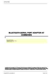
1.0 General Description The National Semiconductor LMX9820A Bluetooth Serial Port module is a highly integrated radio, baseband controller, and memory device implemented on an FR4 substrate. All hardware and firmware is included to provide a complete solution from antenna from the complete lower and upper layers of the Bluetooth stack, up to the application support layers including the Generic Access Profile (GAP), the Service Discovery Application Profile (SDAP), and the Serial Port Profile (SPP). The module includes a configurable service database to fulfill service requests for additional profiles on the host. The LMX9820A features a small form factor (10.1 x 14.1 x 2.0 mm) design, which solves many of the challenges associated with compact system integration. Moreover, the LMX9820A is pre-qualified as a Bluetooth Integrated Component. Conformance testing through the Bluetooth qualification program enables a fast time to market after system integration by ensuring a high degree of compliance and interoperability.
The firmware supplied with this device offers a complete Bluetooth (v1.1) stack including profiles and command interface. This firmware features point-to-point and pointto-multipoint link management supporting data rates up to the theoretical maximum over RFComm of 704 kbps. The internal memory supports up to three active Bluetooth data links and one active SCO link.
1.1 APPLICATIONS ■ Personal Digital Assistants ■ POS Terminals ■ Data Logging Systems ■ Audio Gateway applications
2.0 Functional Block Diagram
FIRMWARE (INCLUDES
LINK MGMNT PROCESSOR (LMP)
UART
PROFILES AND COMMAND
UART_RX UART_TX UART_RTS# UART_CTS#
INTERFACE) IOVCC TX_SWITCH_P ENV0
ANTENNA
AUX LNA TR SW
DIGITAL
BASEBAND
SMART RADIO
CONTROLLER
PORTS
COMPACTRISC™ CORE
PA
SYNTHESIZER
FLASH
RAM
ADVANCED AUDIO INTERFACE
INTERFACE SELECT
JTAG
VOLTAGE
ANALOG
REGULATORS
DIGITAL
ENV1 LSTAT_0 LSTAT_1 HOST_WU RESET_B# RESET_5100#
ISEL1 ISEL2
VDD_ANA_OUT VDD_DIG_OUT VDD_DIG_PWR_D#
CRYSTAL/OSCILLATOR
AAI_STD AAI_SFS AAI_SRD AAI_SCLK
VCC
DIG_GND[1:2]
CompactRISC is a trademark of National Semiconductor Corporation. Bluetooth is a registered trademark of Bluetooth SIG, Inc. and is used under license by National Semiconductor.
© 2005 National Semiconductor Corporation
www.national.com
LMX9820A Bluetooth Serial Port Module
APRIL 2005
LMX9820A Bluetooth Serial Port Module
3.0 Features ■ ■ ■ ■
– File Transfer Protocol (FTP) – Object Push Profile (OPP) – Headset (HSP) – Handsfree Profile (HFP) ■ On-chip application support including: – Command Interface: – Link setup and configuration (also Multipoint) – Configuration of the module – In-System Programming (ISP) – Service database modifications – Default connections – UART Transparent mode – Different Operation modes: – Automatic mode – Command mode
Bluetooth version 1.1 qualified Implemented in CMOS technology on FR4 substrate Temperature Range: -40°C to +85°C FCC certified on LMX9820ADONGLE, FCC ID ED9LMX9820ASM.
3.1 DIGITAL HARDWARE ■ Baseband and Link Management processors ■ CompactRISC Core ■ Integrated Memory: – Flash – RAM ■ UART Command/Data Port: – Support for up to 921.6k baud rate ■ Auxiliary Host Interface Ports: – Link Status – Transceiver Status (Tx or Rx) – Operating Environment Control: – Default Bluetooth mode – In System Programming (ISP) mode ■ Advanced Power Management (APM) features ■ Advanced Audio Interface for external PCM codec
3.3 DIGITAL SMART RADIO ■ Accepts external clock or crystal input: – 12 MHz – 20 ppm cumulative clock error required for Bluetooth ■ Synthesizer: – Integrated VCO and loop filter – Provides all clocking for radio and baseband functions ■ Antenna Port (50 ohms nominal impedance): – Embedded front-end filter for enhanced out of band performance ■ Integrated transmit/receive switch (full-duplex operation via antenna port) ■ Typical -81 dBm input sensitivity ■ 0 dBm typical output power
3.2 FIRMWARE ■ Complete Bluetooth Stack including: – Baseband and Link Manager – L2CAP, RFCOMM, SDP – Profiles: – GAP – SDAP – SPP ■ Additional Profile support on host for any SPP based profile, like – Dial Up Networking (DUN) – Facsimile Profile (FAX)
3.4 PHYSICAL DIMENSIONS ■ Compact size: 10.1mm x 14.1mm x 2.0mm ■ Complete system interface provided in Land Grid Array on underside for surface-mount assembly ■ Metal shield included
Figure 1. Physical Illustration
www.national.com
2
Revision 1.0
1.0 2.0 3.0
4.0 5.0 6.0
7.0
8.0
9.0 10.0
General Description . . . . . . . . . . . . . . . . . . . . . . . . . . . . 1 1.1 APPLICATIONS . . . . . . . . . . . . . . . . . . . . . . . . . . . 1 Functional Block Diagram . . . . . . . . . . . . . . . . . . . . . . . 1 Features . . . . . . . . . . . . . . . . . . . . . . . . . . . . . . . . . . . . . . 2 3.1 DIGITAL HARDWARE . . . . . . . . . . . . . . . . . . . . . . 2 3.2 FIRMWARE . . . . . . . . . . . . . . . . . . . . . . . . . . . . . . 2 3.3 DIGITAL SMART RADIO . . . . . . . . . . . . . . . . . . . . 2 3.4 PHYSICAL DIMENSIONS . . . . . . . . . . . . . . . . . . . 2 Connection Diagram . . . . . . . . . . . . . . . . . . . . . . . . . . . . 4 Pad Descriptions . . . . . . . . . . . . . . . . . . . . . . . . . . . . . . 5 Electrical Specifications . . . . . . . . . . . . . . . . . . . . . . . . 8 6.1 GENERAL SPECIFICATIONS . . . . . . . . . . . . . . . . 8 6.2 DC CHARACTERISTICS . . . . . . . . . . . . . . . . . . . . 9 6.3 RF PERFORMANCE CHARACTERISTICS . . . . 10 6.4 PERFORMANCE DATA (TYPICAL) . . . . . . . . . . 12 Functional Description . . . . . . . . . . . . . . . . . . . . . . . . . 14 7.1 BASEBAND AND LINK MANAGEMENT PROCESSORS 14 7.1.1 Bluetooth Lower Link Controller . . . . . . . . . . . . 14 7.1.2 Bluetooth Upper Layer Stack . . . . . . . . . . . . . . 14 7.1.3 Profile Support . . . . . . . . . . . . . . . . . . . . . . . . . 14 7.1.4 Application with Command Interface . . . . . . . . 14 7.2 MEMORY . . . . . . . . . . . . . . . . . . . . . . . . . . . . . . . 15 7.3 CONTROL AND TRANSPORT PORT . . . . . . . . . 15 7.4 AUXILIARY PORTS . . . . . . . . . . . . . . . . . . . . . . . 15 7.4.1 Reset_5100 and Reset_b# . . . . . . . . . . . . . . . 15 7.4.2 Operating Environment Pads (Env0 and Env1) 15 7.4.3 Interface Select Inputs (ISEL1, ISEL2) . . . . . . 15 7.4.4 Module and LInk Status Outputs . . . . . . . . . . . 15 7.5 AUDIO PORT . . . . . . . . . . . . . . . . . . . . . . . . . . . . 16 Digital Smart Radio . . . . . . . . . . . . . . . . . . . . . . . . . . . . 17 8.1 FUNCTIONAL DESCRIPTION . . . . . . . . . . . . . . 17 8.2 RECEIVER FRONT END . . . . . . . . . . . . . . . . . . . 17 8.2.1 Poly-Phase Bandpass Filter . . . . . . . . . . . . . . . 17 8.2.2 Hard Limiter and RSSI . . . . . . . . . . . . . . . . . . . 17 8.3 RECEIVER BACK END . . . . . . . . . . . . . . . . . . . . 17 8.3.1 Frequency Discriminator . . . . . . . . . . . . . . . . . 17 8.3.2 Post-Detection Filter and Equalizer . . . . . . . . . 17 8.4 AUTOTUNING CIRCUITRY . . . . . . . . . . . . . . . . . 17 8.5 SYNTHESIZER . . . . . . . . . . . . . . . . . . . . . . . . . . 17 8.5.1 Phase-Frequency Detector . . . . . . . . . . . . . . . 17 8.6 TRANSMITTER CIRCUITRY . . . . . . . . . . . . . . . . 18 8.6.1 IQ-DA Converters and TX Mixers . . . . . . . . . . 18 8.7 CRYSTAL REQUIREMENTS . . . . . . . . . . . . . . . 18 8.7.1 Crystal . . . . . . . . . . . . . . . . . . . . . . . . . . . . . . . 18 8.7.2 TCXO (Temperature Compensated Crystal Oscillator) 21 8.7.3 ESR (Equivalent Series Resistance) . . . . . . . . 22
Revision 1.0
11.0
12.0
13.0
14.0
15.0 16.0 17.0
3
System Power-Up Sequence . . . . . . . . . . . . . . . . . . . Integrated Firmware . . . . . . . . . . . . . . . . . . . . . . . . . . 10.1 FEATURES . . . . . . . . . . . . . . . . . . . . . . . . . . . . 10.1.1 Operation Modes . . . . . . . . . . . . . . . . . . . . . . 10.1.2 Default Connections . . . . . . . . . . . . . . . . . . . . 10.1.3 Event Filter . . . . . . . . . . . . . . . . . . . . . . . . . . . 10.1.4 Default Link Policy . . . . . . . . . . . . . . . . . . . . . 10.1.5 Audio Support . . . . . . . . . . . . . . . . . . . . . . . . . Power Reduction . . . . . . . . . . . . . . . . . . . . . . . . . . . . . 11.1 LOW POWER MODES . . . . . . . . . . . . . . . . . . . . 11.2 UART TRANSPORT LAYER CONTROL . . . . . . 11.2.1 Hardware Wake-Up Functionality . . . . . . . . . . 11.2.2 Disabling the UART Transport Layer . . . . . . . 11.2.3 LMX9820A Enabling the UART Interface . . . . 11.2.4 Enabling the UART Transport Layer from Host Command Interface . . . . . . . . . . . . . . . . . . . . . . . . . . . 12.1 FRAMING . . . . . . . . . . . . . . . . . . . . . . . . . . . . . . 12.1.1 Start and End Delimiters . . . . . . . . . . . . . . . . . 12.1.2 Packet Type ID . . . . . . . . . . . . . . . . . . . . . . . . 12.1.3 Opcode . . . . . . . . . . . . . . . . . . . . . . . . . . . . . . 12.1.4 Data Length . . . . . . . . . . . . . . . . . . . . . . . . . . 12.1.5 Checksum . . . . . . . . . . . . . . . . . . . . . . . . . . . . 12.2 COMMAND SET OVERVIEW . . . . . . . . . . . . . . Usage Scenarios . . . . . . . . . . . . . . . . . . . . . . . . . . . . . 13.1 SCENARIO 1: POINT-TO-POINT CONNECTION 32 13.2 SCENARIO 2: AUTOMATIC POINT-TO-POINT CONNECTION 33 13.3 SCENARIO 3: POINT-TO-MULTIPOINT CONNECTION 34 Application Information . . . . . . . . . . . . . . . . . . . . . . . 14.1 MATCHING NETWORK . . . . . . . . . . . . . . . . . . . 14.2 FILTERED POWER SUPPLY . . . . . . . . . . . . . . . 14.3 HOST INTERFACE . . . . . . . . . . . . . . . . . . . . . . 14.4 CLOCK INPUT . . . . . . . . . . . . . . . . . . . . . . . . . . 14.5 SCHEMATIC AND LAYOUT EXAMPLES . . . . . Soldering . . . . . . . . . . . . . . . . . . . . . . . . . . . . . . . . . . . Physical Dimensions . . . . . . . . . . . . . . . . . . . . . . . . . Datasheet Revision History . . . . . . . . . . . . . . . . . . . .
23 24 24 24 24 24 24 24 26 26 26 26 26 26 26 27 27 27 27 27 27 27 28 32
35 35 35 35 35 35 39 41 42
www.national.com
LMX9820A Bluetooth Serial Port Module
Table of Contents
LMX9820A Bluetooth Serial Port Module
4.0 Connection Diagram 1
2
3
4
5
6
7
8
9
10
11
12
13
NC
NC
NC
NC
NC
NC
NC
PI1_ RF_CE_TP11
NC
Tx_rx_ synch
CCB_ Clock
BBCLK
PI2_TP12
NC
RF GND
RF GND
RF GND
RF GND
RF GND
RF GND
Clk-
Clk+
AAI_srd
Env1
AAI_std
32kHz_CLKI
NC
RF GND
RF GND
RF GND
RF GND
RF GND
RF GND
Tx_rx_ data
Uart_rx
Uart_rts#
AAI_sfs
AAI_sclk
32kHz_CLKO
NC
RF GND
RF GND
RF GND
RF GND
RF GND
RF GND
CCB_data
Uart_tx
Uart_cts#
Reset_ 5100#
Dig_gnd_1
NC
NC
RF GND
RF GND
RF GND
RF GND
RF GND
RF GND
Lstat_0
Env0
J_rdy
USB_D+
USB_D-
NC
NC
RF GND
RF GND
RF GND
RF GND
RF GND
RF GND
Lstat_1
Host_wu
J_tdi
J_tdo
NC
RF GND
RF GND
RF GND
RF GND
RF GND
NC
Reset_b#
J_tms
J_tck
NC
VCC
TX_ Switch_P
NC
RF GND
RF GND
RF GND
RF_inout
RF GND
RF GND
RF GND
IOVCC
ISEL2
NC
NC
NC
CCB_ latch
ISEL1
A
B
C
D
E
F USB_VCC PH3_TP9
G Dig_gnd_2 USB_Gnd PH2_TP8
H
J NC
VDD_ANA_OUT NC VDD_DIG_OUT NC VDD_DIG_PWR_D#
NC
X-Ray (Top View)
Figure 2. Connection Diagram
Table 1. Ordering Information Order Number
www.national.com
Shipment Method
LMX9820ASM
Tape & Reel 250 pcs
LMX9820ASMX
Tape & Reel 2000 pcs
4
Revision 1.0
Table 2. System Interface Signals Pad Location
Direction
Description
Clk-
B8
Input
Xtal g or Negative Clock Input. Typically connected along with XTAL_D to an external surface-mount AT-cut crystal. Leave not connected in case Clk+ is connected to external crystal oscillator.
Clk+
B9
Input
Xtal d or Positive Clock Input. Typically connected along with XTAL_G to an external surface-mount AT-cut crystal. Can also be configured as a frequency input when using an external crystal oscillator. When configured as a frequency input, typically connected to an external Temperature Compensated Crystal Oscillator (TCXO) through an Alternating Current (AC) coupling capacitor.
32kHz_CLKI
B13
Input
32 kHz Clock input. Not supported by LMX9820A. Connect to ground. Pad required for mechanical stability.
32kHz_CLKO
C13
Output
32 kHz Clock Output. Not supported by LMX9820A. Treat as no connect. Pad required for mechanical stability.
RF_inout
H8
Input/Output
RF Antenna Port. 50Ω nominal impedance. Typically connected to an antenna through a 6.8 pF capacitor.
ISEL2
H13
Input
Module Interface Select Input Bit 1
ISEL1
J13
Input
Module Interface Select Input Bit 0
Pad Name
Table 3. USB Interface Signals (not supported by LMX9820A firmware) Pad Location
Direction
USB_VCC
F12
Input
USB_D+
E11
Input/Output
USB Data Positive 1
USB_D-
E12
Input/Output
USB Data Negative 1
USB_Gnd
G12
Input
Pad Name
1.
Description USB Transceiver Power Supply + 1
USB Transceiver Ground. Connect to GND.
Treat as no connect. Pad required for mechanical stability.
Table 4. UART Interface Signals Pad Location
Direction
Uart_tx
D9
Output
UART Host Control Interface Transport, Transmit Data
Uart_rx
C9
Input
UART Host Control Interface Transport, Receive Data
Uart_rts#
C10
Output
Uart_cts#
D10
Input
Pad Name
1. 2.
Description
UART Host Control Interface Transport, Request to Send 1 UART Host Control Interface Transport, Clear to Send 2
Treat as no connect if not used. Pad required for mechanical stability. Connect GND if not used.
Revision 1.0
5
www.national.com
LMX9820A Bluetooth Serial Port Module
5.0 Pad Descriptions
LMX9820A Bluetooth Serial Port Module
5.0 Pad Descriptions (Continued) Table 5. Auxiliary Ports Interface Signals Pad Location
Direction
H12
Input
2.85V to 3.6V Logic Threshold Program Input.
Reset_b#
G8
Input
Reset for Smart Radio. Connect to Reset_5100.
Reset_5100#
D11
Input
Reset for Baseband processor. Low active, either connect to host or use pull-up with max. 1KΩ resistor.
Lstat_0
E8
Output
Link Status Bit 0
Lstat_1
F8
Output
Link Status Bit 1
Host_wu
F9
Output
Host Wakeup
Env0
E9
Input
Module Operating Environment Bit 0
Env1
B11
Input
Module Operating Environment Bit 1
TX_Switch_P
H3
Output
Pad Name IOVCC
Description
Transceiver Status. 0 = Receive; 1 = Transmit.
Table 6. Audio Port Interface Signals Pad Location
Direction
AAI_srd
B10
Input
AAI_std
B12
Output
AAI_sfs
C11
Input/Output
Advanced Audio Interface Frame Synchronization 1
AAI_sclk
C12
Input/Output
Advanced Audio Interface Clock 1
Pad Name
1.
Description Advanced Audio Interface Receive Data Input 1 Advanced Audio Interface Transmit Data Output 1
Treat as no connect if not used. Pad required for mechanical stability. Table 7. Test Interface Signals Pad Location
Direction
J_rdy
E10
Output
J_tdi
F10
Input
JTAG Test Data 1
J_tdo
F11
Input/Output
JTAG Test Data 1
J_tms
G9
Input/Output
JTAG Test Mode Select 1
J_tck
G10
Input
PI1_RFCE_TP11
A8
Test Pin
Module Test Point 1
PI2_TP12
A13
Test Pin
Module Test Point 1
Tx_rx_data
C8
Test Pin
Module Test Point 1
Tx_rx_synch
A10
Test Pin
Module Test Point 1
CCB_Clock
A11
Test Pin
Module Test Point 1
CCB_data
D8
Test Pin
Module Test Point 1
CCB_latch
J12
Test Pin
Module Test Point 1
BBCLK
A12
Test Pin
Module Test Point 1
PH3_TP9
F13
Test Pin
Module Test Point 1
PH2_TP8
G13
Test Pin
Module Test Point 1
Pad Name
www.national.com
Description JTAG Ready 1
JTAG Test Clock 1
6
Revision 1.0
1.
Treat as no connect. Pad required for mechanical stability.
Table 8. Power, Ground, and No Connect Signals Pad Name
Pad Location
Direction
Description
NC
A1, A2, A3, A4, A5, A6, A7, A9, B1, C1, D1, D13, E1, E13, F1, G1, G7, H1, H4, J1, J3, J6, J7, J9, J10, J11
No Connect
RF GND 1
B2, B3, B4, B5, B6, B7, C2, C3, C4, C5, C6, C7, D2, D3, D4, D5, D6, D7, E2, E3, E4, E5, E6, E7, F2, F3, F4, F5, F6, F7, G2, G3, G4, G5, G6, H5, H6, H7, H9, H10, H11
Input
Radio System Ground. Must be connected to RF Ground plane. Thermal relief required for proper soldering.
Dig_gnd_1 1
D12
Input
Digital Ground
Dig_gnd_2 1
G11
Input
Digital Ground
VCC
H2
Input
2.85V to 3.6V Input for Internal Power Supply Regulators
VDD_ANA_OUT
J2
Output
Voltage Regulator Output/Power Supply for Analog Circuitry. If not used, place pad and do not connect to VCC or Ground.
VDD_DIG_OUT
J5
Output
Voltage Regulator Output/Power Supply for Digital Circuitry. If not used, place pad and do not connect to VCC or Ground.
VDD_DIG_PWR_D#
J4
Input
1.
No Connect. Pad required for mechanical stability.
Power Down for the Internal Power Supply Regulator for the Digital Circuitry. Place pad and do not connect to VCC or Ground.
Connect RF GND, Dig_gnd_1, and Dig_gnd_2 to a single ground plane.
Revision 1.0
7
www.national.com
LMX9820A Bluetooth Serial Port Module
5.0 Pad Descriptions (Continued)
LMX9820A Bluetooth Serial Port Module
6.0 Electrical Specifications
The following conditions apply unless otherwise stated in the tables below:
6.1 GENERAL SPECIFICATIONS
• TA = -40°C to +85°C
Absolute Maximum Ratings (see Table 9) indicate limits beyond which damage to the device may occur. Operating Ratings (see Table 10) indicate conditions for which the device is intended to be functional.
• VCC = 3.3V, IOVCC = 3.3V • RF system performance specifications are guaranteed on National Semiconductor Austin Board rev1.0b reference design platform.
This device is a high performance RF integrated circuit and is ESD sensitive. Handling and assembly of this device should be performed at ESD free workstations.
Table 9. Absolute Maximum Ratings Min
Max
Unit
VCC
Symbol
Core Logic Power Supply Voltage
-0.3
4.0
V
IOVCC
I/O Power Supply Voltage
-0.3
4.0
V
USB_VCC1
USB Power Supply Voltage
-0.5
3.63
V
VI
Voltage on any pad with GND = 0V
-0.5
3.6
V
PinRF
RF Input Power
+15
dBm
TS
Storage Temperature Range
+125
oC
TL
Lead Temperature (solder 4 sec)
+235
oC
ESD-HBM
ESD, Human Body Model
2000 2
V
ESD-MM
ESD, Machine Model
200
V
1. 2.
Parameter
-65
USB Interface not supported by LMX9820A firmware. Treat as no connect. Pad required for mechanical stability. Antenna pin passes 1500V HBM.
Table 10. Recommended Operating Conditions1 Symbol
Parameter
Min
Typ 2
Max
Unit
VCC3
Module Power Supply Voltage
2.85
3.3
3.6
V
IOVCC 4
I/O Power Supply Voltage
2.85
3.3
3.6
V
tR
Module Power Supply Rise Time
50
ms
TO
Operating Temperature Range
-40
+85
°C
HUMOP
Humidity (operating, across operating temperature range)
10
90
%
HUMNONOP
Humidity (non-operating, 38.7oC web bulb temperature)
5
95
%
1. 2. 3. 4.
Maximum voltage difference allowed between VCC and IOVCC is 500 mV. Typical operating conditions are VCC = 3.3V, IOVCC = 3.3V operating voltage and 25°C ambient temperature. VCC internally regulated to VDD_ANA (see Table 11) IOVCC internally regulated to VDD_DIG (see Table 11)
Table 11. Power Supply Electrical Specifications (Analog and Digital LDOs) Symbol
Parameter
Min
Typ1
Max
Unit
VDD_ANA_OUT2
Analog Voltage Output Range
2.8
V
VDD_DIG_OUT3
Digital Voltage Output Range
2.5
V
1. 2. 3.
Typical operating conditions are VCC = 3.3V, IOVCC = 3.3V operating voltage and 25°C ambient temperature. Values reflect voltages of internally generated, regulated voltages VDD_ANA and VDD_DIG Output of internally generated regulated voltage VDD_ANA Output of internally generated regulated voltage VDD_DIG
www.national.com
8
Revision 1.0
Note: The voltage regulators are optimized for the internal operation of the LMX9820A. Because any noise coupled into these supplies can have influence on the radio perfor-
mance, it is highly recommended to have no additional load on their outputs.
Table 12. Power Supply Requirements1 Symbol
Parameter
Min
Typ2
Max
Unit
ICC-TX
Power supply current for continuous transmit
68
mA
ICC-RX
Power supply current for continuous receive
62
mA
ICC-Inq
Inquiry
31
mA
IRXSL
Receive Data in SPP Link, slave 3,4
23
mA
IRXM
Receive Data in SPP Link, master 3,4
18
mA
IHV3
Active HV3 SCO Audio Link
22
mA
ISnM
Sniff Mode, sniff interval 1 second 3
8
mA
ISC-TLDIS
Scanning, no active link, TL disabled 3,5
2.5
mA
IIdle
Idle, scanning disabled, TL disabled 3,5
0.15
mA
1. 2. 3. 4. 5.
Power supply requirements based on Class II output power. VCC = 3.3V, IOVCC = 3.3V, Ambient Temperature = +25°C. Average values. Based on UART Baudrate 115.2kbit/s. TL: Transport Layer
6.2 DC CHARACTERISTICS Table 13. Digital DC Characteristics Symbol
Parameter
Condition
Min
Max
Units
VCC 1
Core Logic Supply Voltage
2.85
3.6
V
IOVCC2
IO Supply Voltage
2.85
3.6
V
VIH
Logical 1 Input Voltage
0.7 x VDD_ANA
VDD_ANA + 0.5
V
VIL
Logical 0 Input Voltage
-0.5
0.2 x VDD_ANA
V
VHYS
Hysteresis Loop Width3
0.1 x VDD_ANA
V
IOH
Logical 1 Output Current
VDD_ANA = 2.8V
-1.6
mA
IOL
Logical 0 Output Current
VDD_ANA = 2.8V
1.6
mA
IOHW
Weak Pull-up Current
VDD_ANA = 2.8V
-10
µA
IIH
High-level Input Current
VIH = VDD_ANA = 2.8V
- 10
10
µA
IIL
Low-level Input Current
VIL = 0
- 10
10
µA
IL
High Impedance Input Leakage Current
0V ≤ V IN ≤ VDD_ANA
-2.0
2.0
µA
IO(Off)
Output Leakage Current (I/O pins in input mode)
0V ≤ V OUT ≤ VDD_DIG
-2.0
2.0
µA
1. 2. 3.
VCC internally regulated to VDD_ANA (see Table 11) IOVCC internally regulated to VDD_DIG (see Table 11) Guaranteed by design.
Revision 1.0
9
www.national.com
LMX9820A Bluetooth Serial Port Module
6.0 Electrical Specifications (Continued)
LMX9820A Bluetooth Serial Port Module
6.0 Electrical Specifications (Continued) • TA = -40°C to +85°C • VCC = 3.3V, IOVCC = 3.3V unless otherwise specified
6.3 RF PERFORMANCE CHARACTERISTICS In the performance characteristics tables the following applies:
RF system performance specifications are guaranteed on National Semiconductor Austin Board rev1.0b reference design platform.
• All tests performed are based on Bluetooth Test Specification rev 0.92. • All tests are measured at antenna port unless otherwise specified
Table 14. Receiver Performance Characteristics Symbol RXsense 2
Parameter Receive Sensitivity
PinRF
Maximum Input Level
C/IACI3
Carrier to Interferer Ratio in the Presence of Adjacent Channel Interferer
C/IIMAGE -1MHz Carrier to Interferer Ratio in the Presence of Image-1MHz Interferer IMP3,4
Intermodulation Performance
RSSI
RSSI Dynamic Range at LNA Input
ZRFIN
Input Impedance of RF Port (RF_inout)
Return Loss3
Return Loss
OOB3
Out Of Band Blocking Performance
1. 2. 3.
Typ1
Max
Unit
2.402 GHz
-81
-77
dBm
2.441 GHz
-81
-77
dBm
2.480 GHz
-81
-77
dBm
Condition BER < 0.001
Min
-10
0
dBm
∆FACI = + 1 MHz, PinRF = -60 dBm, BER < 0.001
-1
dB
∆FACI = + 2 MHz. PinRF = -60 dBm, BER < 0.001
-37
dB
∆FACI = + 3 MHz, PinRF = -67 dBm, BER < 0.001
-47
dB
∆f = -3 MHz, PinRF = -67 dBm, BER < 0.001
-32
dB
F1= + 3 MHz, F2= + 6 MHz, PinRF = -64 dBm
-38
-36
-72 Single input impedance Fin = 2.45 GHz
dBm
-52
dBm Ω
50 -8
dB
PinRF = -10 dBm, 30 MHz < FCWI < 2 GHz, BER < 0.001
-10
dBm
PinRF = -27 dBm, 2000 MHz < FCWI < 2399 MHz, BER < 0.001
-27
dBm
PinRF = -27 dBm, 2498 MHz < FCWI < 3000 MHz, BER < 0.001
-27
dBm
PinRF = -10 dBm, 3000 MHz < FCWI < 12.75 GHz, BER < 0.001
-10
dBm
Typical operating conditions are at 2.85V operating voltage and 25°C ambient temperature. The receiver sensitivity is measured at the device interface. Not tested in production.
www.national.com
10
Revision 1.0
4.
The f0 = -64 dBm Bluetooth modulated signal, f1 = -39 dbm sine wave, f2 = -39 dBm Bluetooth modulated signal, f0 = 2f1 - f2, and |f2 - f1| = n x 1 MHz, in which n is 3, 4, or 5. For the typical case, n = 3.
Table 15. Transmitter Performance Characteristics Symbol
Parameter Transmit Output Power
POUTRF 2
Min Typ1
Condition
Max
Unit
2.402 GHz
-3
+1
+4
dBm
2.441 GHz
-3
+1
+4
dBm
2.480 GHz
-3
+1
+4
dBm
-4
1
2
dBm
175
kHz
Power Density 5
Power Density
MOD ∆F1AVG
Modulation Characteristics
Data = 00001111
140
165
MOD ∆F2MAX 3
Modulation Characteristics
Data = 10101010
115
125
∆F2AVG/∆F1AVG 4
Modulation Characteristics
kHz
0.8
20 dB Bandwidth
1000
kHz
Adjacent Channel Power (In-band Spurious)
|M-N|=2
-48
-20
dBm
|M-N|>3
-51
-40
dBm
POUT2*fo 6
PA 2nd Harmonic Suppression
Maximum gain setting: f0 = 2402 MHz, Pout = 4804 MHz
-30
dBm
POUT3*fo 5
PA 3rd Harmonic Suppression
Maximum gain setting: f0 = 2402 MHz, Pout = 7206 MHz
-32
dBm
ZRFOUT
RF Output Impedance/Input Impedance of RF Port (RF_inout)
Pout @ 2.5 GHz
Return Loss 5
Return Loss
ACP 5
1. 2. 3. 4. 5. 6.
Ω
50
-14
dB
Typical operating conditions are at VCC = 3.3V, IOVCC = 3.3V operating voltage and 25°C ambient temperature. The output power is measure at the device interface. ∆F2max > 115 kHz for at least 99.9% of all ∆f2max. Modulation index set between 0.28 and 0.35. Not tested in production. Out-of-Band spurs only exist at 2nd and 3rd harmonics of the CW frequency for each channel. Table 16. Synthesizer Performance Characteristics Symbol
Parameter
Condition
Min
Typ
Max
Unit
fVCO
VCO Frequency Range
tLOCK
Lock Time
f0 + 20 kHz
∆f0offset 1,2
Initial Carrier Frequency Tolerance
During preamble
-75
0
75
kHz
∆f0drift 2,3
Initial Carrier Frequency Drift
DH1 data packet
-25
0
25
kHz
DH3 data packet
-40
0
40
kHz
DH5 data packet
-40
0
40
kHz
Drift Rate
-20
0
20
kHz/50µs
tD-Tx
Revision 1.0
Transmitter Delay Time
From Tx data to antenna
11
5000
MHz
120
µs
4
µs
www.national.com
LMX9820A Bluetooth Serial Port Module
6.0 Electrical Specifications (Continued)
LMX9820A Bluetooth Serial Port Module
6.0 Electrical Specifications (Continued) 1. 2. 3.
Frequency accuracy is dependent on crystal oscillator chosen. The crystal must have a cumulative accuracy of 15 ppm @ -40 to +85°C
CL Load Capacitance
16 pF
ESR
80Ω max.
C0 Shunt Capacitance
5 pF
Drive Level
50 ±10uV
Pullability
2 ppm/pF min
Storage Temperature
-40 to +85°C
Table 22. TEW on Arizona Board
www.national.com
20
Reference
LMX9820A
Ct1
10 pF
Ct2
10 pF
Revision 1.0
LMX9820A Bluetooth Serial Port Module
8.0 Digital Smart Radio (Continued) Figure 12. Frequency Offset with 12 pF/12 pF Capacitors
Figure 13. Frequency Offset with 10 pF/10 pF Capacitors Table 23. TCXO NKG3184A
8.7.2 TCXO (Temperature Compensated Crystal Oscillator)
Specification
The LMX9820A also can operate with an external TCXO (Temperature Compensated Crystal Oscillator). The TCXO signal is directly connected to the CLK+, shown in Table 23 on page 21.
Value
Package
5.0 x 3.2 x 1.4 mm (4 pads)
Frequency
12.000 MHz
Stability
1. Input Impedance The LMX9820A CLK+ pin has in input impedance of 2 pF capacitance in parallel with >400kΩ resistance.
18 ppm at -30 to +85°C (inclusive of all conditions)
Output Load
10kΩ/13 pF
2. NKG3184A TCXO The LMX9820A has also been tested with the NKG3184A TCXO. See Table 23 on page 21.
Current Consumption
2.0 mA
Output Level
0.3Vp-p to 2.0Vp-p
Storage Temperature
-40 to +85°C
DC Cut Capacitor
Included in VC-TCXO
Revision 1.0
21
www.national.com
LMX9820A Bluetooth Serial Port Module
8.0 Digital Smart Radio (Continued) 8.7.3 ESR (Equivalent Series Resistance) LMX9820A can operate with a wide range of crystals with different ESR ratings. Reference Table 24 on page 22 and Figure 14 on page 22 for more details. Table 24. System Clock Requirements Parameter
Min
External Reference Clock Frequency
Typ
Max
12 MHz
Frequency Tolerance (over full operating temperature and aging)
15
Crystal Serial Resistance External Reference Clock Power Swing, pk to pk
100
Aging
200
Unit MHz
20
ppm
230
Ω
400
mV
1
ppm per year
Figure 14. ESR vs. Load Capacitance for the Crystal
www.national.com
22
Revision 1.0
9.0 System Power-Up Sequence
2. Reset_b# and Reset_5100# of the LMX9820A are driven high a minimum of 2 ms after the LMX9820A voltage rails are high. The LMX9820A is the properly reset. See Table 25 on page 23.
The following sequence must be performed to correctly power-up the LMX9820A: 1. Apply IOVCC and VCC to the LMX9820A.
VCC tPTOR
IOVCC
Reset_b# Reset_5100
Low
BBP_CLOCK
Low
TX_RX_DATA
High
Low
TX_RX_SYNC
Low
CCB_DATA
Low
CCB_CLOCK
High
CCB_LATCH
LMX9820A
LMX9820A
Oscillator
Initialization
Standby
Active
LMX9820A
Start-Up
Initialization
LMX9820A in Normal Mode
LMX9820A in Power-Up Mode
Figure 15. LMX9820A System Power-Up Sequence Timing
Table 25. LMX9820A System Power-up Sequence Timing Symbol
Parameter
Condition
tPTOR
Power to Reset
VCC and IO VCC at operating voltage level to valid reset
Revision 1.0
23
Min 2
Typ
Max
Unit ms
www.national.com
LMX9820A Bluetooth Serial Port Module
9.0 System Power-Up Sequence (Continued)
LMX9820A Bluetooth Serial Port Module
10.0 Integrated Firmware (Continued) 10.0 Integrated Firmware
nected by another device, it will not switch to transparent mode and continue to interpret data sent on the UART.
The LMX9820A includes the full Bluetooth protocol stack up to RFComm to support the following profiles:
Transparent Mode
— GAP (Generic Access Profile) — SDAP (Service Discovery Application Profile) — SPP (Serial Port Profile) Figure 16 shows the Bluetooth protocol stack with command interpreter interface. The command interpreter offers a number of different commands to support the functionality given by the different profiles. Execution and interface timing is handled by the control application.
If activated, the module does not interpret the commands on the UART which normally are used to configure and control the module. In this case, the packets do not need to be formatted as described in Table 28 on page 27. Instead, all data are directly passed through the firmware to the active Bluetooth link and the remote device.
The LMX9820A supports transparent data communication from the UART interface to a Bluetooth link.
Transparent mode can only be supported on a point-topoint connection. To leave Transparent mode, the host must send a UART_BREAK signal to the module
The chip has an internal data area in Flash that includes the parameters shown in Table 26 on page 25.
Force Master Mode In Force Master mode, the LMX9820A tries to act like an Access point for multiple connections. In this mode, it will only accept a link if a master/slave role switch is accepted by the connecting device. After successful link establishment, the LMX9820A will be master and available for additional incoming links. On the first incoming link the LMX9820A may switch to transparent mode, depending on the setting for automatic or command mode. Additional links will only be possible if the device is not in transparent mode.
Command Interpreter
Control Application
SPP
SDAP
GAP
10.1.2 Default Connections RFComm
SDP
The LMX9820A supports the storage of up to 3 default connections within its NVS. Those connections can either be connected after reset or on demand using a specific command.
L2CAP
Link Manager
10.1.3 Event Filter Baseband
The LMX9820A uses events or indicators to notify the host about successful commands or changes on the Bluetooth interface. Depending on the application, the LMX9820A can be configured. The following levels are defined:
Figure 16. LMX9820A Software Implementation
10.1 FEATURES 10.1.1 Operation Modes
• No Events—the LMX9820A is not reporting any events. Optimized for passive cable replacement solutions.
On boot-up, the application configures the module following the parameters in the data area.
• Standard LMX9820A Events—only necessary events will be reported.
Automatic Mode
• All Events—additional to the standard all changes at the physical layer will be reported.
No Default Connections Stored In Automatic mode the module is connectable and discoverable and automatically answers to service requests. The command interpreter listens to commands and links can be set up. The full command list is supported.
10.1.4 Default Link Policy Each Bluetooth link can be configured to support master/slave role switch, Hold mode, Sniff mode, and Park mode. The default link policy defines the standard setting for incoming and outgoing connections.
If connected by another device, the module sends an event back to the host, where the RFComm port has been connected, and switches to transparent mode.
10.1.5 Audio Support
Default Connections Stored
The LMX9820A offers commands to establish and release synchronous connections (SCO) to support Headset or Handsfree applications. The firmware supports one active link with all available package types (HV1, HV2, HV3), for routing audio data between the Bluetooth link and the advanced audio interface. To provide the analog data interface, an external audio codec is required. The LMX9820A includes a list of codecs which can be used.
If default connections were stored on a previous session, after the LMX9820A is reset, it will attempt to reconnect to each device stored within the data Flash three times. The host will be notified about the success of the link setup via a link status event. Command Mode In Command mode, the LMX9820A does not check the default connections section within the Data Flash. If conwww.national.com
24
Revision 1.0
Table 26. Operation Parameters Stored in LMX9820A Parameter
Default Value
Description
BDADDR
(Hardcoded into device)
Bluetooth device address
Local Name
Serial port device
PinCode
0000
Bluetooth PinCode
Operation Mode
Automatic
Command or Automatic mode
Default Connections
0
Up to three default devices to connect on default
SDP Database
1 SPP entry: Name: COM1 Authentication and encryption enabled
Service discovery database, control for supported profiles
UART Speed
9600
Sets the speed of the physical UART interface to the host
UART Settings
1 Stop bit, parity disabled
Parity and stop bits on the hardware UART interface
Ports to Open
0000 0001
Defines the RFComm ports to open
Link Keys
No link keys
Link keys for paired devices
Security Mode
2
Security mode
Page Scan Mode
Connectable
Connectable/Not connectable for other devices
Inquiry Scan Mode
Discoverable
Discoverable/Not Discoverable/Limited Discoverable for other devices
Default Link Policy
All modes allowed
Configures modes allowed for incoming or outgoing connections (master/slave role switch, Hold mode, Sniff mode, Park mode)
Default Link Timeout
20 seconds
The Default Link Timeout configures the timeout, after which the link is assumed lost, if no packages have been received from the remote device.
Event Filter
Standard LMX9820A events reported
Defines the level of reporting on the UART - No events - Standard events - Standard including ACL link events
Default Audio Settings
None
Configures the settings for the external codec and the air interface format. • Codecs: — Motorola MC145483 — OKI MSM7717 • Air format: — CVSD — µ-Law — A-Law
Revision 1.0
25
www.national.com
LMX9820A Bluetooth Serial Port Module
10.0 Integrated Firmware (Continued)
LMX9820A Bluetooth Serial Port Module
11.0 Power Reduction (Continued) 11.0 Power Reduction The LMX9820A supports several low-power modes to reduce power in different operating situations. The modular structure of the LMX9820A allows the firmware to power down unused modules. The low-power modes have influence on: • UART transport layer—enables or disables the interface. • Bluetooth Baseband activity—firmware disables LLC and radio, if possible.
CTS#
TX
TX
RX
RX
GPIO
Figure 17. UART Null Modem Connections 11.2.2 Disabling the UART Transport Layer The host can disable the UART transport layer by sending the “Disable Transport Layer” Command. The LMX9820A will empty its buffers, send the confirmation event, and disable its UART interface. The UART interface will then be reconfigured to wake up the LMX9820A on a falling edge of the CTS pin.
The activity of the Bluetooth radio mainly depends on application requirements and is controlled by standard Bluetooth operations such as inquiry/page scanning or an active link. A remote device establishing or disconnecting a link may also indirectly change the activity level of the radio.
11.2.3 LMX9820A Enabling the UART Interface
The UART transport layer by default is enabled on device power up. The “Disable Transport Layer” command is used to disable the transport layer. Therefore, only the host-side command interface can disable the transport layer. Enabling the transport layer is controlled by the hardware wake-up signalling. This can be initiated from either the host or an LMX9820A input. See also “LMX9820A Software Users Guide” for detailed information on timing and implementation requirements.
Because the transport layer can be disabled in any situation, the LMX9820A must verify that the transport layer is enabled before sending data to the host. Possible situations in which the LMX9820A will need to re-enable the interface include incoming data or incoming link indicators. If the UART is not enabled, the LMX9820A must assume that the host is in a low-power mode and initiate a wake-up event by asserting RTS and setting HOST_WU to 1. To be able to respond to the wake-up event, the host must monitor its CTS input (i.e. the LMX9820A RTS output).
Table 27. Power Mode Activity UART
RTS#
(optional)
The following LMX9820A power modes, which depend on the activity level of the UART transport layer and the radio activity, are defined:
Bluetooth Radio
RTS# CTS#
Host_WU
11.1 LOW POWER MODES
Power Mode
Host
LMX9820A
As soon as the host activates its RTS output (i.e. the LMX9820A CTS input), the LMX9820A will first send a confirmation event and then start to transmit the events.
Reference Clock
PM0
Off
Off
None
PM1
On
Off
12 MHz
PM2
Off
Scanning
12 MHz
PM3
On
Scanning
12 MHz
PM4
Off
SPP Link
12 MHz
PM5
On
SPP Link
12 MHz
11.2.4 Enabling the UART Transport Layer from Host If the host needs to send data or commands to the LMX9820A while the UART transport layer is disabled, it must first assume that the LMX9820A is sleeping and wake it up by asserting the host RTS output (i.e. the LMX9820A CTS input). When the LMX9820A detects the wake-up signal, it enables the UART and acknowledges the wake-up signal by asserting its RTS output and HOST_WU signal. Additionally, the wake-up event will be acknowledged by sending a confirmation event. When the host has received this “Transport Layer Enabled” event, it knows the LMX9820A is ready to receive commands.
11.2 UART TRANSPORT LAYER CONTROL 11.2.1 Hardware Wake-Up Functionality In some circumstances, the host may switch off the transport layer of the LMX9820A to reduce power consumption. The host and LMX9820A then may shut down their UART interfaces. To simplify the system design, the UART interface is configured for hardware wake-up functionality. For a detailed timing and command functionality, see the “LMX9820A Software Users Guide”. The interface between the host and LMX9820A is shown in Figure 17.
www.national.com
26
Revision 1.0
12.0 Command Interface
12.1.2 Packet Type ID This byte identifies the type of packet. See Table 29 for details.
The LMX9820A offers Bluetooth functionality through either a self-contained slave functionality or a simple command interface. The interface is carried over the UART interface.
12.1.3 Opcode The opcode identifies the command to execute. The opcode values can be found within the “LMX9820A Software User’s Guide” included with the LMX9820A Evaluation Board.
The following sections describe the protocol on the UART interface between the LMX9820A and the host in command mode (see Figure 18). In Transparent mode, no data framing is necessary and the device does not interpret data carried over the interface as commands.
12.1.4 Data Length Number of bytes in the Packet Data field. The maximum size is 333 data bytes per packet.
12.1 FRAMING The connection is considered “Error free”. But for packet recognition and synchronization, some framing is used.
12.1.5 Checksum
All packets sent in both directions are constructed following the model shown in Table 28.
This is a simple Block Check Character (BCC) checksum of the bytes “Packet type”, “Opcode”, and “Data Length”. The BCC checksum is calculated as low byte of the sum of all bytes (e.g., if the sum of all bytes is 0x3724, the checksum is 0x24).
12.1.1 Start and End Delimiters The “STX” character is used as the start delimiter: STX = 0x02. ETX = 0x03 is used as the end delimiter.
Existing device without Bluetooth™ LMX9820A
capabilities UART
UART
Figure 18. Bluetooth Functionality . Table 28. Packet Framing Start Delimiter
Packet Type ID
Opcode
Data Length
Checksum
Packet Data
End Delimiter
1 Byte
1 Byte
1 Byte
2 Bytes
1 Byte
Bytes
1 Byte
- - - - - - - - - - - - - Checksum - - - - - - - - - - - - -
Table 29. Packet Type Identification ID
Direction
Description
0x52
REQUEST
A request sent to the Bluetooth module.
‘R’
(REQ)
All requests are answered by exactly one confirm.
0x43
Confirm
The Bluetooth modules confirm to a request.
‘C’
(CFM)
All requests are answered by exactly one confirm.
0x69
Indication
Information sent from the Bluetooth module that is not a direct confirm to a request.
‘i’
(IND)
Indicating status changes, incoming links, or unrequested events.
0x72
Response
An optional response to an indication.
‘r’
(RES)
This is used to respond to some type of indication message.
Revision 1.0
27
www.national.com
LMX9820A Bluetooth Serial Port Module
12.0 Command Interface (Continued)
LMX9820A Bluetooth Serial Port Module
12.0 Command Interface (Continued) Tables 30 through 40 show the actual command set and the events coming back from the device. A fully documented description of the commands can be found in the “LMX9820A Software Users Guide”.
12.2 COMMAND SET OVERVIEW The LMX9820A has a well-defined command set to: • Configure the device: – Hardware settings – Local Bluetooth parameters – Service database
Note: For standard Bluetooth operation, only commands from Table 30 through Table 32 are used. Most of the remaining commands are only for configuration purposes.
• Set up and handle links Table 30. Device Discovery Commands Command Inquiry
Remote Device Name
Event
Description
Inquiry Complete
Search for devices
Device Found
Lists BDADDR and class of device
Remote Device Name Confirm
Get name of remote device
Table 31. SDAP Client Commands Command
Event
Description
SDAP Connect
SDAP Connect Confirm
Create an SDP connection to remote device
SDAP Disconnect
SDAP Disconnect Confirm
Disconnect an active SDAP link
Connection Lost
Notification for lost SDAP link
SDAP Service Browse
Service Browse Confirm
Get the services of the remote device
SDAP Service Search
SDAP Service Search Confirm
Search a specific service on a remote device
SDAP Attribute Request
SDAP Attribute Request Confirm
Searches for services with specific attributes
Table 32. SPP Link Commands Command Establish SPP Link
Event
Description
Establishing SPP Link Confirm
Initiates link establishment to a remote device
Link Established
Link successfully established
Incoming Link
A remote device established a link to the local device
Set Link Timeout
Set Link Timeout Confirm
Confirms the supervision timeout for the existing link
Get Link Timeout
Get Link Timeout Confirm
Get the supervision timeout for the existing link
Release SPP Link
Release SPP Link Confirm
Initiate release of SPP link
SPP Send Data
SPP Send Data Confirm
Send data to specific SPP port
Incoming Data
Incoming data from remote device
Transparent Mode Confirm
Switch to transparent mode on the UART
Transparent Mode
Table 33. Default Connection Commands Command
Event
Description
Connect Default Connection
Connect Default Connection Confirm
Connects to either one or all stored default connections
Store Default Connection
Store Default Connection Confirm
Store device as default connection
Get List of Default Connections
List of Default Devices
Delete Default Connections
Delete Default Connections Confirm
www.national.com
28
Revision 1.0
Table 34. Power Mode Commands Command
Event
Description
Set Default Link Policy
Set Default Link Policy Confirm
Defines the link policy used for any incoming or outgoing link.
Get Default Link Policy
Get Default Link Policy Confirm
Returns the stored default link policy
Set Link Policy
Set Link Policy Confirm
Defines the modes allowed for a specific link
Get Link Policy
Get Link Policy Confirm
Returns the actual link policy for the link
Enter Sniff Mode
Enter Sniff Mode Confirm
Exit Sniff Mode
Exit Sniff Mode Confirm
Enter Park Mode
Enter Park Mode Confirm
Enter Hold Mode
Enter Hold Mode Confirm Power Save Mode Changed
Remote device changed the power save mode on the link
Table 35. Audio Control Commands Command Establish SCO Link Release SCO Link
Event
Description
Establish SCO Link Confirm
Establish SCO link on existing RFComm link
Release SCO Link Confirm
Release SCO link
SCO Link Established Indicator
A remote device has established a SCO link to the local device
SCO Link Released Indicator
SCO link has been released
Change SCO Packet Type Confirm
Changes packet type for existing SCO link
SCO Packet Type changed indicator
SCO packet type has been changed
Set Audio Settings
Set Audio Settings Confirm
Set audio settings for existing link
Get Audio Settings
Get Audio Settings Confirm
Get audio settings for existing link
Set Volume
Set Volume Confirm
Configure the volume
Get Volume
Get Volume Confirm
Get current volume setting
Mute
Mute Confirm
Mutes the microphone input
Change SCO Packet Type
Table 36. Wake Up Function Commands Command Disable Transport Layer
Revision 1.0
Event
Description
Transport Layer Enabled
Disabling the UART transport layer and activates the hardware wake-up function
29
www.national.com
LMX9820A Bluetooth Serial Port Module
12.0 Command Interface (Continued)
LMX9820A Bluetooth Serial Port Module
12.0 Command Interface (Continued)
Table 37. SPP Port Configuration and Status Commands Command
Event
Description
Set Port Config
Set Port Config Confirm
Set port setting for the “virtual” serial port link over the air
Get Port Config
Get Port Config Confirm
Read the actual port settings for a “virtual” serial port
Port Config Changed
Notification if port settings were changed from remote device
SPP Get Port Status
SPP Get Port Status Confirm
Returns status of DTR and RTS (for the active RFComm link)
SPP Port Set DTR
SPP Port Set DTR Confirm
Sets the DTR bit on the specified link
SPP Port Set RTS
SPP Port Set RTS Confirm
Sets the RTS bit on the specified link
SPP Port BREAK
SPP Port BREAK
Indicates that the host has detected a break
SPP Port Overrun Error
SPP Port Overrun Error Confirm
Used to indicate that the host has detected an overrun error
SPP Port Parity Error
SPP Port Parity Error Confirm
Host has detected a parity error
SPP Port Framing Error
SPP Port Framing Error Confirm
Host has detected a framing error
SPP Port Status Changed
Indicates that remote device has changed one of the port status bits
Table 38. Local Settings Commands Command
Event
Description
Read Local Name
Read Local Name Confirm
Read user-friendly name of the device
Write Local Name
Write Local Name Confirm
Set the user-friendly name of the device
Read Local BDADDR
Read Local BDADDR Confirm
Change Local BDADDR
Change Local BDADDR Confirm
Store Class of Device
Store Class of Device Confirm
Set Scan Mode
Set Scan Mode Confirm
Change mode for discoverability and connectability
Set Scan Mode Indication
Reports end of automatic limited discoverable mode
Get Fixed Pin
Get Fixed Pin Confirm
Reads current PinCode stored within the device
Set Fixed Pin
Set Fixed Pin Confirm
Set the local PinCode
Get Security Mode
Get Security Mode Confirm
Get actual Security mode
Set Security Mode
Set Security Mode Confirm
Configure Security mode for local device (default 2)
Remove Pairing
Remove Pairing Confirm
Remove pairing with a remote device
List Paired Devices
List of Paired Devices
Get list of paired devices stored in the LMX9820A data memory
Set Default Link Timeout
Set Default Link Timeout Confirm
Store default link supervision timeout
Get Default Link Timeout
Get Default Link Timeout Confirm
Get stored default link supervision timeout
Force Master Role
Force Master Role Confirm
Enables/Disables the request for master role at incoming connections
www.national.com
30
Note:
Only use if you have your own BDADDR pool
Revision 1.0
Table 39. Local Service Database Configuration Commands Command
Event
Description
Store SPP Record
Store SPP Record Confirm
Create a new SPP record within the service database
Store DUN Record
Store DUN Record Confirm
Create a new DUN record within the service database
Store FAX Record
Store FAX Record Confirm
Create a new FAX record within the service database
Store OPP Record
Store OPP Record Confirm
Create a new OPP record within the service database
Store FTP Record
Store FTP Record Confirm
Create a new FTP record within the service database
Store IrMCSync Record
Store IrMCSync Record Confirm
Create a new IrMCSync record within the service database
Enable SDP Record
Enable SDP Record Confirm
Enable or disable SDP records
Delete All SDP Records
Delete All SDP Records Confirm
Ports to Open
Ports to Open Confirmed
Specify the RFComm Ports to open on startup
Table 40. Local Hardware Commands Command
Event
Description
Set Default Audio Settings
Set Default Audio Settings Confirm
Configure default settings for audio codec and air format, stored in NVS
Get Default Audio Settings
Get Default Audio Settings Confirm
Get stored default audio settings
Set Event Filter
Set Event Filter Confirm
Configures the reporting level of the command interface
Get Event Filter
Get Event Filter Confirm
Get the status of the reporting level
Read RSSI
Read RSSI Confirm
Returns an indicator for the incoming signal strength
Change UART Speed
Change UART Speed Confirm
Set specific UART speed; needs proper ISEL pin setting
Change UART Settings
Change UART Settings Confirm
Change configuration for parity and stop bits
Test Mode
Test Mode Confirm
Enable Bluetooth, EMI test, or local loopback
Restore Factory Settings
Restore Factory Settings Confirm
Reset
Dongle Ready
Soft reset
Firmware Upgrade
Revision 1.0
Stops the Bluetooth firmware and executes the in-system programming code
31
www.national.com
LMX9820A Bluetooth Serial Port Module
12.0 Command Interface (Continued)
LMX9820A Bluetooth Serial Port Module
13.0 Usage Scenarios (Continued) 13.0 Usage Scenarios
The SPP conformance of the LMX9820A allows any device using the SPP to connect to the LMX9820A.
13.1 SCENARIO 1: POINT-TO-POINT CONNECTION
By switching to transparent mode automatically, the controller has no need for an additional protocol layer; data is sent raw to the other Bluetooth device.
LMX9820A acts only as slave, no further configuration is required.
On default, a PinCode is requested to block unallowed targeting.
Example: Sensor with LMX9820A; hand-held device with standard Bluetooth option.
Air Interface Sensor Device
Standard Device with Bluetooth UART Inquiry Request
Search for Devices
Inquiry Response
SDP Link Request
Get Remote Services
SDP Link Accept
Service Browse Service Response
Release SDP Link Release Confirm
Connected on Port L
SPP Link Request
Establish SPP Link
SPP Link Accept
Link Established
Transparent Mode
Raw Data
LMX9820A
Microcontroller
No Bluetooth commands necessary, only “connected” event indicated to controller.
The client software only shows high level functions.
Figure 19. Point-to-Point Connection
www.national.com
32
Revision 1.0
If step 5 is executed, the stored default device is connected (step 4) after reset (in automatic mode only) or by sending the “Connect to Default Device” command. The command can be sent to the device at any time.
13.2 SCENARIO 2: AUTOMATIC POINT-TO-POINT CONNECTION LMX9820A at both sides. Example: Serial Cable Replacement.
If step 6 is left out, the microcontroller has to use the “Send Data” command, instead of sending data directly to the module.
Device #1 controls the link setup with a few commands as described.
Serial Device #1
Serial Device #2 Air
1. Devices in Range?
Interface Inquiry
Inquiry
Inquiry Result
Inquiry Result
Inquiry Response
Establish SDP Link
Establish SDP Link
SDP Link Request
SDP Link Established
SDP Link Established
SDP Link Accept
Service Browse
Service Browse
Service Browse
RFComm Port = R
Browse Result
Service Response
Release SDP Link
Release SDP Link
Release SDP Link
SDP Link Released
SDP Link Released
Release Confirm
SPP Link Request
Inquiry Request
2. Choose the Device 3. Which COM Port is available?
4. Create SPP Link Establish SPP Link
Establish SPP Link
to Port R1 on Port L2
to Port R on Port L
Connected on Port L
Link Established
SPP Link Accept
Connected on Port R
5. Connect on Default Transparent Mode
(Optional) Store Default Device
Storing Default Device
Device Stored
Device Stored
6. Switch to Transparent Transparent Mode
Transparent Mode
Raw Data
Microcontroller
LMX9820A
LMX9820A
Bluetooth device controls link with
Microcontroller
No Bluetooth commands necessary;
a few commands.
only “connected” event indicated to controller.
1. Port R indicates the remote RFComm channel to connect to. Usually the result of the SDP request. 2. Port L indicates the Local RFComm channel used for that connection. Figure 20. Automatic Point-to-Point Connection
Revision 1.0
33
www.national.com
LMX9820A Bluetooth Serial Port Module
13.0 Usage Scenarios (Continued)
LMX9820A Bluetooth Serial Port Module
13.0 Usage Scenarios (Continued) Serial Device #1 is acting as master for both devices. The host controls which device is sending data, using the “Send data” command. If the device receives data from the other devices, it is packaged into an “Incoming data” event. The event includes the device related port number.
13.3 SCENARIO 3: POINT-TO-MULTIPOINT CONNECTION LMX9820A acts as master for several slaves. Example: Two sensors with LMX9820A; one hand-held master device with LMX9820A.
If necessary, a link configuration can be stored as default in the master Serial Device #1 to enable the automatic reconnect after reset, power-up, or by sending the “connect default connection” command.
Serial Devices #2 and #3 establish the link automatically as soon as they are contacted by another device. No controller interaction is necessary for setting up the Bluetooth link. Both switch automatically into transparent mode. The host sends raw data over the UART.
Serial Device #2
Serial Device #1 Air Interface Connect to Device #2
Connect to Device #2
see Scenario 2
see Scenario 2
Link Established
Link Established
Connection Request
Automatic Link Setup
on Port L1
Connected on Port L
Transparent Mode
Send Data to Port L1
Send Data Command Raw Data
Data Received
Receive Data Event
from Port L1 LMX9820A
Microcontroller
Serial Device #3
Connect to Device #3
Connect to Device #3
see Scenario 2
see Scenario 2
Link Established
Link Established
Connection Request
Automatic Link Setup
on Port L2
Connected on Port L
Transparent Mode
Send Data to Port L2
Send Data Command Raw Data
Data Received
Receive Data Event
from Port L2 Microcontroller
LMX9820A
LMX9820A
Microcontroller
Figure 21. Point-to-Multipoint Connection
www.national.com
34
Revision 1.0
14.0 Application Information
ISEL2 (pad H13) and ISEL1 (pad J13) can be strapped to the host logic 0 and 1 levels to set the host interface bootup configuration. Alternatively both ISEL2 and ISEL1 can be hardwired over 10kΩ pullup/pulldown resistors. Env0 (pad E9) and Env1 (pad B11) can be left unconnected (both are pulled high), if no ISP capability is required. If the ISP environment mode is needed, then Env0 must be driven to logic low and Reset needs to be asserted. After de-assertion of Reset, the LMX9820A boots into the mode corresponding to the values present on Env0 and Env1. Alternatively, a firmware upgrade command can be used.
Figure 22 on page 35 represents a typical system schematic for the LMX9820A.
14.1 MATCHING NETWORK The antenna matching network may or may not be required, depending upon the impedance of the antenna chosen. A 6.8 pF blocking capacitor is recommended.
14.2 FILTERED POWER SUPPLY It is important to provide the LMX9820A with adequate ground planes and a filtered power supply. It is highly recommended that a 0.1 µF and a 10 pF bypass capacitor be placed as close as possible to VCC (pad H2) on the LMX9820A.
14.4 CLOCK INPUT The clock source must be placed as close as possible to the LMX9820A. The quality of the radio performance is directly related to the quality of the clock source connected to the oscillator port on the LMX9820A. Careful attention must be paid to the crystal/oscillator parameters or radio performance could be drastically reduced.
14.3 HOST INTERFACE To set the logic thresholds of the LMX9820A to match the host system, IOVCC (pad H12) must be connected to the logic power supply of the host system. It is highly recommended that a 10 pF bypass capacitor be placed as close as possible to the IOVCC pad on the LMX9820A. VCC
10 pF
IOVCC
0.01 µF
10 pF
H2 B1 Antenna
14.5 SCHEMATIC AND LAYOUT EXAMPLES
0.01 µF
H12
6.8 pF H8
C9
RF_inout
Connect to system UART bus.
Uart_rx D9
B13
Uart_tx 32kHz_CLKI
No HW Flowcontrol: - CTS GND - RTS NC
D10 Uart_cts C10 Uart_rts
B9
VCC
Clk+ 12 MHz
D11
Y1
Reset_5100 B8 LMX9820A
ClkCt1
max 1KΩ
Reference Table 25 on page 23 for correct POR timing.
G8 Reset_b
Ct2
Connect to PCM codec or leave open
B10
E9
AAI_srd Env0
B12
B11
AAI_std
Reference Table 17 on page 15.
Env1
C11 AAI_sfs C12 AAI_sclk
J13 ISEL1 Dig_gnd[1:2]
RF GND
H13
Reference Table 18 on page 15.
ISEL2
D12, G11
Notes: Capacitor values, Ct1 and Ct2 may vary depending on board design crystal manufacturer specification. Single ground plane is used for both RF and digital grounds.
Figure 22. Example System Schematic
Revision 1.0
35
www.national.com
LMX9820A Bluetooth Serial Port Module
14.0 Application Information (Continued)
LMX9820A Bluetooth Serial Port Module
14.0 Application Information (Continued)
Figure 23. Component Placement (Layer 1)
www.national.com
36
Revision 1.0
LMX9820A Bluetooth Serial Port Module
14.0 Application Information (Continued)
Figure 24. Solid Ground Plane (Layer 2)
Figure 25. Signal Plane (Layer 3)
Revision 1.0
37
www.national.com
LMX9820A Bluetooth Serial Port Module
14.0 Application Information (Continued)
Figure 26. Component Layout Bottom (Layer 4)
www.national.com
38
Revision 1.0
15.0 Soldering
the temperature at which the solder has molten components. The temperature that melting starts at.
The LMX9820A bumps are designed to melt as part of the Surface Mount Assembly (SMA) process. The LMX9820A is assembled with a high-temperature solder alloy to ensure there are no re-reflow conditions imposed upon the module when reflowed to a PCB with these typical low temperature 60/40 (S = 183°C, L = 188°C), 62/36/2 (E = 179°C), or 63/37 (E = 183°C) solder alloys.
• E: Eutectic – Denotes solid to liquid without a plastic phase. The low-temperature solder alloy will reflow with the solder bump and provide the maximum allowable solder-joint reliability. Reflow at a peak of 215 --> 220°C (approximately 30 seconds at peak). Do not to exceed 220°C, measured in close proximity of the modules. to avoid any potential re-reflow conditions.
Where: • S: Solidus – Denotes the points in a phase diagram representing the temperature at which the solder composition begins to melt during heating, or complete freezing during cooling.
Table 41 and Figure 27 on page 40 provide the soldering details required to properly solder the LMX9820A to standard PCBs. The illustration serves only as a guide and National is not liable if a selected profile does not work.
• L: Liquidus – Denotes the points in a phase diagram representing Table 41. Soldering Details Parameter
Value
PCB Land Pad Diameter
24 mil
PCB Solder Mask Opening
30 mil
PCB Finish (HASL details)
63/37 (difference in thickness < 28 micron)
Stencil Aperture
28 mil
Stencil Thickness
5 mil
Solder Paste Used
Low temperature 60/40 (S = 183°C, L = 188°C), 62/36/2 (E = 179°C), or 63/37 (E = 183°C) solder alloys1
Flux Cleaning Process
No Clean Flux System 1
Reflow Profiles 1.
See Figure 27 on page 40
Typically defined by customer.
Revision 1.0
39
www.national.com
LMX9820A Bluetooth Serial Port Module
15.0 Soldering (Continued)
LMX9820A Bluetooth Serial Port Module
15.0 Soldering (Continued)
Profile #
Peak (°C)
Min. (°C)
Max. Rising Slope (°C/s)
Max. Falling Slope (°C/s)
Rising Time 130°C (s)
Time Between 130°C/ 160°C (s)
Rising Time 160°C (s)
Time Between 160°C/ 183°C (s)
Total Time Above 183°C (s)
1
213.9
32.8
2.50
-1.60
208.01
109.00
99.01
57.00
75.00
2
206.7
31.1
2.41
-1.73
213.01
121.01
92.00
53.00
64.00
Figure 27. Typical Reflow Profiles
www.national.com
40
Revision 1.0
LMX9820A Bluetooth Serial Port Module
16.0 Physical Dimensions (Continued) 16.0 Physical Dimensions
NOTES: PAD PITCH IS 1.00 MILLIMETER (.0394”) NON-ACCUMULATIVE. UNLESS OTHERWISE SPECIFIED, ALL DIMENSIONS ARE IN MILLIMETER. TOLERANCE, UNLESS OTHERWISE SPECIFIED: TWO PLACE (.00): ±.01 THREE PLACE (.000): ±.002 ANGULAR: ±1° Figure 28. FR4 Package
Revision 1.0
41
www.national.com
LMX9820A Bluetooth Serial Port Module
17.0 Datasheet Revision History (Continued) 17.0 Datasheet Revision History
stages/definitions of the datasheet. Table 43 lists the revision history and Table 44 lists the specific edits to create the current revision.
This section is a report of the revision/creation process of the datasheet for the LMX9820A. Table 42 provides the
Table 42. Documentation Status Definitions Datasheet Status
Product Status
Definition
Advance Information
Formative or in Design
This datasheet contains the design specifications for product development. Specifications may change in any manner without notice.
Preliminary
First Production
This datasheet contains preliminary data. Supplementary data will be published at a later date. National Semiconductor Corporation reserves the right to make changes at any time without notice in order to improve design and supply the best possible product.S
No Identification Noted
Full production
This datasheet contains final specifications. National Semiconductor Corporation reserves the right to make changes at any time without notice in order to improve design and supply the best possible product.
Obsolete
Not in Production
This datasheet contains specifications on a product that has been discontinued by National Semiconductor Corporation. The datasheet is printed for reference information only.
Table 43. Revision History Revision # (PDF Date) 0.4 (April 2003) 0.6 (February 2004)
Revisions/Comments Initial Datasheet revised to include new radio and additional functionality. Several edits have been made to functional, performance, and electrical details. Updated RF performance values Added 32 kHz frequency support.
0.7 (August 2004)
Updated General Description and Features with Audio Updated Pinout Information Added Audio Section Updated Command Section with audio commands
0.71 (August 2004)
Reviewed Crystal Support Section Added Audio block to application diagram
0.72 (October 2004)
Updated package size Table 9 to Table 15 updated Optional 32.768 kHz crystal support removed Package outline drawing updated to 14.1mm width and 2.0mm height
0.73 (December 2004)
In Table 15, maximum output power range updated to +4dBm.
0.80 (March 2005)
Minor edits for clarity, language, units, formatting, etc. No functional changes.
0.81 (March 2005)
Minor changes in feature list Table 2 updated Added footnote to Table 10 Added description in chapter 6.2 Table 20 updated
0.82 ( March 2005)
Added footnote to Table 13 Figure 22 updated
www.national.com
42
Revision 1.0
LMX9820A Bluetooth Serial Port Module
17.0 Datasheet Revision History (Continued) Table 43. Revision History Revision # (PDF Date)
Revisions/Comments
1.0 draft 1 (March 2005)
Updated Power consumption Table 12
1.0 draft 2 (April 2005)
No functional Update
1.0 draft 3 (April 2005)
Updated C/I in Table 14
1.0 (April 2005)
No functional Update
Table 44. Edits to current revision Section
Revisions/Comments
General Description
•
Connection Diagram
•
Pad Description
•
Electrical Specifications
•
Functional Description
•
Digital Smart Radio
•
System Power Up Sequence
•
Integrated Firmware
•
Low Power Modes
•
Command Interface
•
Application| Information
•
Soldering
•
Physical Dimensions
•
Revision 1.0
43
www.national.com
LMX9820A Bluetooth Serial Port Module National does not assume any responsibility for use of any circuitry described, no circuit patent licenses are implied and National reserves the right at any time without notice to change said circuitry and specifications. For the most current product information visit us at www.national.com.
LIFE SUPPORT POLICY NATIONAL’S PRODUCTS ARE NOT AUTHORIZED FOR USE AS CRITICAL COMPONENTS IN LIFE SUPPORT DEVICES OR SYSTEMS WITHOUT THE EXPRESS WRITTEN APPROVAL OF THE PRESIDENT AND GENERAL COUNSEL OF NATIONAL SEMICONDUCTOR CORPORATION. As used herein: 1. Life support devices or systems are devices or systems which, (a) are intended for surgical implant into the body, or (b) support or sustain life, and whose failure to perform, when properly used in accordance with instructions for use provided in the labeling, can be reasonably expected to result in a significant injury to the user.
2. A critical component is any component of a life support device or system whose failure to perform can be reasonably expected to cause the failure of the life support device or system, or to affect its safety or effectiveness.
BANNED SUBSTANCE COMPLIANCE National Semiconductor certifies that the products and packing materials meet the provisions of the Customer Products Stewardship Specification (CSP-9-111C2) and the Banned Substances and Materials of Interest Specification (CSP-9-111S2) and contain no “Banned Substances” as defined in CSP-9-111S2. National Semiconductor Americas Customer Support Center Email:
[email protected] Tel: 1-800-272-9959
National Semiconductor Europe Customer Support Center Fax: +49 (0) 180-530 85 86 Email:
[email protected] Deutsch Tel: +49 (0) 69 9508 6208 English Tel: +44 (0) 870 24 0 2171 Francais Tel: +33 (0) 1 41 91 8790
www.national.com
National Semiconductor Asia Pacific Customer Support Center Email:
[email protected]
National Semiconductor Japan Customer Support Center Fax: 81-3-5639-7507 Email:
[email protected] Tel: 81-3-5639-7560