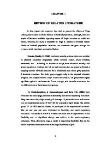
Literature review of impact strength of timber and joints Leijten, Ad. J. M.1 ABSTRACT The use of timber in structures like guard-rail systems requires knowledge about the behaviour at high loading rates. The present study aims at presenting a state of art report with respect to the impact bending strength of timber and to some extent to the behaviour of timber joints at high loading rates. The literature review indicates a difference in the experimental results and the conclusions drawn by code writers. INTRODUCTION The starting point for the determination of many engineering timber properties is the standard short duration test where failure is expected within a few minutes. During the last decades much attention is given to study the behaviour of timber and timber joints with respect to damaging effect of sustained loads, the so-called duration of load effect (DOL). In the design process of timber structures this DOL effect is taken into account by prescribed (reduction) factors. However, there are a number of load cases such as earthquakes and single blasts where timber is exposed to substantially higher loading rates than in the standard short duration test. Examples of single blast loads are explosions but also vehicles that crash against a guard-rail. Both are associated with loading times of a few thousands of a second. In a number of countries like the Netherlands and the USA timber guard-rail systems are being considered as alternatives for the traditional steel guard-rail. Often impact tests showed the ability of wood to withstand impact loads better than standard short duration test. However, the validity of the old test data is questioned as the latest test results show different results. LITERATURE REVIEW OF TIMBER IMPACT TESTS At the beginning of this century studies were performed when aeroplanes were made of wood (McGarvey Cline, 1906). Historically, impact-bending tests were the first types of impact tests. Bodig et.al. (1982) mention the Hatt-Turner test, characterised by the application of impact loads in succession during 1600 the early 1900s and the reason for its later decline. During impact 1400 bending one of several weights 1200 12.5, 25, 50, 100 or 200 lb (1 lb = 1000 0.453 kg) is dropped at mid-span 800 on a simply supported 2 x 2 x 28" (50 x 50 x 710 mm) span wooden 600 beam. The heights of drop increase 400 in successive tests until failure Green 200 occurs or the beam deflects more 12% m.c. 0 than 6" (152 mm). The values in Wood Handbook (1999) refer to 350 400 450 500 550 600 650 experiments with a 22.7 kg (50 lb) Wood density [kg/m3] weight. The height of the maximum drop, or the drop that Figure 2: Wood density versus impact drop height, data of Table 1, according cause failure, is no more than a to the Wood Handbook 1999 comparative value that represents 1
Faculty of Civil Engineering and Geoscience, Delft University of Technology, P.O. Box 5048, 2600 GA Delft, the Netherlands
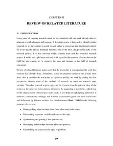
the ability of clear (defect free) wood to absorb shocks that cause stresses beyond the proportional limit. Figure 1 represents some of the test data. Test were performed with wood densities up to 600 kg/m3. Figure 1 only represents one mean value per wood species as the average of the sub species value. The three wood species with the highest drop heights are Hickory (1460 mm), Birch (1230 mm) and Elm (1180 mm). An example of an extreme deviation from the mean is the drop height of 2640 mm for sub-species Shellbark (Hickory) with a density of 620 kg/m3 (not shown in Figure 1). In most cases the deviation for the sub-species is much smaller. The linear regression lines indicate the small influence of the moisture content. This test method only allows comparison between the wood species. Kloot (1954) concluded that the dependency and variation of the impact strength relates more to the test method used than caused by changes in moisture content (m.c. range 4% to 22%). Nevertheless, he showed that at about 10%-15% m.c. the impact resistance is the lowest. For higher and for lower m.c. the impact resistance increases. One of the disadvantages of the impact bending tests with increasing weight drop heights is that at a certain stage the wood fibres can resist the impact but not without substantial damage. The damage leads to a reduced impact resistance and therefore the next time the weight is dropped from the new height the beam fails. Would a weight been dropped immediately from this height the beam might well be able to resist it. Besides impact bending a second impact test method was introduced in the fifties. It was more intended to test the material toughness. In this respect toughness was defined as the work required to break a given specimen in bending under an impact load. Several machines were and still are used to measure the toughness and are based on a pendulum impact hammer, Figure 2. The difference between the energy of the pendulum before and after contact is the energy required to produce failure. Drow et al. (1958) reports that “because different types of machines gives different values standardisation is required and at the moment there is no satisfactory method available to convert data from one test to the other”. Although this test method offers many advantages over the former impact bending test method the standardised Figure 2: Principle of pendulum impact used to dimensions of the specimens is small 20x20x280 mm and only evaluate toughness, (Charpy test) suitable for small clear defect free wood. Comparison with specimens of different size is therefore not simple. During the Second World War, when wood was used to a considerable extent for structural members for training aircraft’s and gliders, it became evident that additional tests data were necessary to improve the understanding of the behaviour of wood under impact load. Therefore, a comprehensive test program was initiated at the Forest Products Laboratory, Madison, US to study the effect of rate of loading on the bending and compression parallel to the grain of two softwoods and two hardwoods; Sitka Spruce, Douglas-fir, Figure 3: Ratio of static and impact bending strength versus loading rate for Maple, Liska (1955). Maple and Birch,
respectively, Liska (1955). The planks were free of defects and as straight grained as possible. The dimensions were small 1x1x4" for compression and for bending 1x2x16" softwoods and 1x1x16" for hardwoods at 14" span. The equilibrium moisture content ranged from 9 to 14%. Loading times ranged from 0.3 to 150 seconds. The bending tests were performed in a hydraulic testing machine with a constant head movement. The average of the controls (reference) mentioned in Figure 3 refer to the standard bending test results. The modification factors for accidental loading in many timber engineering design codes are based on these results. In the Figure 3 the observations are presented for Maple. The data for the other wood species follow the same tendency. The bending strength increases with higher loading rates for all wood species tested. At the highest rate the strength is about 20 to 30% higher than the standardised bending strength. It should be noted that all reported investigations above deal with clear defect free specimens. In the seventies researchers started to test timber of commercially size for impact strength. Jansson (1992) reports tests by Spencer (1978) of Douglas-Fir lumber (38x140x3660mm) loaded at eight different loading rates. The constant rates of loading tests were performed in edge wise four point bending with a clear span of 2515 mm. The observation was that the bending strength of stronger beams increased as the loading rate increased while the low bending strength beams did not responded to higher loading rates in the same way. Apparently, the presence of defects changed the behaviour. More recently Madsen et. Figure 4: Test set-up by Madsen et al. (1986) and Jansson (1992) al. (1986) studied the impact bending strength on simply supported timber beams by dropping a weight from various heights. The three point loading was accomplished by a fit to purpose built machine, Figure 4. The drop height of the 345 kg weight varied. Spruce beams of two commercial sizes were tested; 38x134x914 mm with a span 610 mm and 102x203x1530 mm with a span of 1220 mm. The smallest size beams were sampled in three categories. A) Defect free beams. B) Beams with a 35 mm square notch on the tension side of the beam. C) A knot at the tension side near the loading point. A drop height of 610 mm resulted in an impact velocity of 3,3 m/s. For the larger beams the weight was dropped from 1.5, 1.75 and 2.0m height resulting in an impact velocity of 5.1, 5.5 and 5.9 m/s respectively. On the basis of the test results of the smaller beams it was concluded that the fibre length of the fractured part were much shorter than compared to the static bending test. For the more instrumented larger beams it was concluded that the bending strength and the fracture energies were lower than compared to the static bending test. The mean bending strength under impact appears to be 75% of the static strength. For the lower tail of the strength distribution the affect appears to be less dramatic. However, the test set-up did have a number of shortcomings that affected the strength results one of which was the indentation of the compression zone caused by the loading tup. It was Jansson (1992) who continued the test sequence by Madsen et al. (1986) but changed the test set-up in a way the indentation was strongly reduced. He reports 651 impact tests with the same apparatus on Spruce beams with dimensions of 38 x 89 x 145 mm (2"x 4"x 45") with a clear span of 1095 mm. The specimens were divided into two groups, defect free material in the middle half (class 1 material) and in beams with knots in these sections. Subgroups were loaded in three point static (standardised) bending. The average bending Figure 5: Final results of impact tests by Jansson (1992) strength of defect free material was 82.1 MPa and 67.3 MPa for the population with knots. For the impact tests the weight of 345 kg was dropped from 50, 150 and 300 mm height resulting in a maximum impact velocity of 2,3 m/s. The average times to failure were 25, 17 and 10 milliseconds. Essential in these tests by Jansson ( also for Madsen) is that the impact force was measured directly by means of a load cell between the drop weight and the test specimen. In the analyses of the results Jansson (1992) reports
the importance of separating the applied load in two parts. Firstly, a part which introduce the bending stresses and secondly a part which sets the beam in motion. After all, compared to the standardised bending test the mass of the beam is set in motion so rapidly that inertia forces could no longer be disregarded. It should be pointed out that in all previous tests the inertia forces were always disregarded, as they were assumed negligible. Analytical procedures earlier developed by Bentur et al. (1986) to estimate the inertia effect were explored. Critical in the analytical estimation of the inertia forces was the shape of the deflected beam. Two solutions were derived which depended on the deformed shape of the beam, obviously. In the first assumption the beam is assumed to deflect in a parabolic way. In the second approach the beam is assumed to stay straight except for the part under the impact loading head where all deformation is concentrated. The effort to determine the beam shape experimentally failed as the reading appeared very unreliable. It was assumed that the false readings were caused by high shock waves that led to uncontrolled movements of the measuring devices. Therefore, Jansson (1992) turned to other methods to estimate the inertia influence. Besides a full exploration of the analytical mechanical representation of the behaviour of such beams he decided to choose for a Modal Analysis approach to tackle the Figure 6: Time [s] versus deflection [m] of beams tested by Jansson. problem. Some of the final results of his work is given in Figure 5.
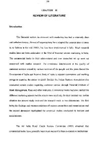
Figure 7: The embedment force versus displacement parallel and perpendicular to the grain direction, according to Girhammer et al. (1988) For clear material (class 1) as well as for the material with knots (class 2) the impact bending strength decreases with decreasing time to failure. The deviation from the test results mentioned earlier is considerable. No strength increase of 20 to 30% but a strength decrease of 15% for the shortest loading time of 10 milliseconds was observed. A FEM based upon time space elements for a Timoshenko beam by A. Kok (1999) shows that the tested beams used in the investigation by Jansson (1992) have shapes that vary with loading time. Sometimes the beam deflects like a parabolic curve sometimes
the curve is like a triangle, Figure 6. At the moment similar test as carried out by Jansson are carried out at TU-Delft but with impact velocities of 7 m/s. LITERATURE REVIEW OF IMPACT TESTS OF TIMBER JOINTS
Figure 8: Load displacement curves of joints with 17 mm (5d) thick middle and side members, all loaded parallel to the grain
Figure 9: Load displacement curves of joints with 34 mm (10d) thick middle and side members, side members loaded parallel to the grain, middle member perpendicular to the grain.
Literature clearly shows a lack of research with respect to high loading rate testing of timber joints. The only reference is the work by Girhammer et. al. (1988). They evaluated the embedment strength and behaviour of three member nailed joints. All members were made of redwood (Pinus Sylvestris) loaded in compression with nails of 3.4 x 100 mm. All tests were performed under deformation control meaning that the loading head moved with a constant speed. The deformation rate varied between 2 mm/s up to 1250 mm/s. The side and middle timber members were of equal thickness and varied in thickness from 5 to 10 times the nail diameter. The load and grain direction corresponded with the middle member while the grain direction of the side members varied from 0 to 900. Besides the nailed joints, the embedment strength was tested for its loading rate dependency with the 3.4 mm diameter nail. The timber thickness of the embedment specimens was 19.2 mm The same loading rates were applied along and perpendicular to the grain as for the joints. It was assumed that the deformation measured was equivalent to the movement of the loading head of the machine. In Figure 7 the embedment-deformation curves are presented as the mean of ten tests for each of the deformation rates. This was justified as the scatter between the results of each group with the same loading rate was small. The same approach was followed for the tests with joints, Figure 8 and 9. It was concluded that the high rate of loading resulted in a substantial increase of the embedment strength and consequently to a higher strength of the nailed joints. Compared to the standard short duration test factors of 1.3 to 1.6 were observed. CONCLUDING The background for the 20% strength increase of timber for impact loading rates is based tests with small clear free specimens. The influence of the inertia forces was neglected. The impact tests on commercial size beams taking into account the inertia forces, indicate the bending strength to decrease for increasing loading rates. Strength reductions up to 15% have been observed. There is a lack of high loading rate data for timber joints. The only test results available indicate an increase of the embedment strength and strength of nailed joints by more than 20%. REFERENCES Bantur,A, Mindess, S, and Banthia, N., 1986, The behaviour of concrete under impact loading: Experimental procedures and method of analysis. Materials and Structures, Vol. 19, No. 113, pp. 371-378. Bodig, J. and Jayne, B. A. 1982, Mechanics of wood and wood composites, ISBN 0-442-00822-8, Van Nostrand Reinhold Company. Drow, J.T., Markwardt, L.J., Youngquist, W.G. 1958, Results of impact tests to compare the pendulum impact and toughness test method, Report 2109, Forest Product Laboratories, Madison, USA. Girhammar, U. and Andersson, H. 1988, Effect of loading rate on nailed timber joint capacity. Journal of Structural Engineering, ASCI, Vol. 114, 1988. Jansson, B. 1992, Impact loading of timber beams, M.Sc. thesis, Faculty of Civil Engineering, University of British Columbia, April. Kloot, N.H. 1954, The effect of moisture content on the impact strength of wood, Australian Journal of applied Science, Vol.5 no.2, pp. 183-186. Liska, J.A., 1955, Effect of rapid loading on the compressive and flexural strength of wood, Report 1767, Forest Products Laboratory, Forest Service, Madison, Wisconsin. Kok, A. 1997, Lumped impulses, discrete displacements and moving load analysis, HERON 1997, vol.42, No. 1, p.3 -23, ISSN 0046-7316 Madsen,B and Mindess, S. 1986, The fracture of wood under impact loading, Material and Structures, Vol. 19, No. 109. Wood Handbook 1999, Wood as a engineering material, Report FPL-GTR-113, Forest Service, Forest Product Laboratory, Madison, Wisconsin.