LICENTIATE THESIS IN STRUCTURAL ENGINEERING AND BRIDGES STOCKHOLM, SWEDEN 2016
Bridge Edge Beams LCCA and Structural Analysis for the Evaluation of New Concepts JOSÉ JAVIER VEGANZONES MUÑOZ
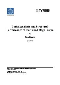
Test DR1a 1800 1600
Load [kN]
1400 1200
1000 800 600 400
Non-linear FEM (Edge beam)
200
Non-linear FEM (No edge beam)
0
0
0,02
0,04
0,06
0,08
Displacement [m]
KTH ROYAL INSTITUTE OF TECHNOLOGY SCHOOL OF ARCHITECTURE AND BUILT ENVIRONMENT
Bridge Edge Beams LCCA AND STRUCTURAL ANALYSIS FOR THE EVALUATION OF NEW CONCEPTS JOSÉ JAVIER VEGANZONES MUÑOZ
Licentiate Thesis, 2016 KTH Royal Institute of Technology School of Architecture and Built Environment Department of Civil and Architectural Engineering Division of Structural Engineering and Bridges SE-100 44, Stockholm, Sweden
II
TRITA-BKN Bulletin 137, 2016 ISSN 1103-4270 ISRN KTH/BKN/B--137--SE © José Javier Veganzones Muñoz, 2016 Akademisk avhandling som med tillstånd av KTH i Stockholm framlägges till offentlig granskning för avläggande av teknisk licentiatexamen fredagen den 12 februari kl. 13:00 i sal Stora konferensrummet (M108), KTH, Brinellvägen 23, Stockholm. Avhandlingen försvaras på engelska.
III
Abstract Bridge edge beams in Sweden may involve up to 60% of the life-cycle measure costs incurred along the road bridge’s life span. Moreover, user costs as means of traffic disturbances are caused. Consequently, the Swedish Transport Administration started a project to find better alternative edge beam design proposals for the society. The goal of this thesis is to contribute to the development of bridge edge beam solutions that can result better for the society in terms of total cost and still fulfill the functional requirements, through the evaluation of new concepts. A life-cycle cost analysis was carried out to assess the proposed alternatives. The results served as a guidance to identify alternatives that could qualify for more detailed studies. One such proposal was a solution without edge beam. Since the edge beam is known to distribute concentrated loads, the removal of such member could lead to loss of robustness of concrete bridge deck slabs. Thus, a structural analysis to determine the influence of the edge beam was performed through nonlinear finite-element modelling validated from experimental evidence available in the literature. An assessment of the existing calculation methods for the overhang slab is also presented. The results show that the edge beam behaves as a load-carrying member which contributes to a wider distribution of shear forces. An increased load resisting capacity for reinforced concrete bridge deck overhang slabs was documented. The removal of the edge beam would imply loss of robustness in the bridge, which might have to be counteracted by an increase of the thickness of the deck slab. Keywords Edge beam, bridge edge beam system, life-cycle cost analysis, bridge deck, overhang slab, structural analysis, design methods, nonlinear, finite element modeling.
IV
V
Sammanfattning Kantbalkar i Sverige kan orsaka upp till 60 % av drift- och underhållskostnader under brons livslängd. Dessutom finns användarkostnader i termer av trafikantstörningar. Som en konsekvens startade Trafikverket ett projekt vars mål var att hitta kantbalkslösningar som kan anses samhällsoptimala. Syftet med denna avhandling är att utveckla de kantbalksutformningar som kan bli bättre för samhället i form av kostnader och kan uppfylla de funktionella och strukturella kraven. En livscykelkostnadsanalys genomfördes för att undersöka de föreslagna lösningarna. Resultaten tolkades som en vägledning för att identifiera förslag som skulle kunna kvalificera sig för mer detaljerade studier. Ett förslag som visade sig vara intressant var en lösning utan kantbalk. Eftersom kantbalken kan fördela koncentrerade laster kan avlägsnandet av en sådan leda till förlust av robusthet av brobaneplattan. Således var inverkan av kantbalken på det strukturella beteendet det som undersöktes genom icke-linjära finit element modeller som validerades från laboratorieförsök i litteraturen. En bedömning av de nuvarande beräkningsmetoderna presenteras också. Resultaten visar att kantbalken uppför sig som ett lastbärande element, som bidrar till en större spridning av tvärkrafter. En ökad lastkapacitet för betongarmerade brobaneplattor dokumenterades. Avlägsnandet av kantbalken skulle innebära förlust av robusthet i brobaneplattan. Detta skulle kunna lösas genom en ökning av plattans tjocklek.
Nyckelord Kantbalkssystem, Livscykelkostnadsanalys, Brobaneplattor, Konsolplattor, Dimensionering, Finit Element Modellering.
VI
VII
Resumen Las vigas de borde en puentes en Suecia pueden causar hasta el 60% de los costes de mantenimiento y reparación durante la vida útil de la estructura. Además, se generan al mismo tiempo altos costes de usuario debido al tráfico provocado por las obras. Por tanto, la Administración de Transportes de Suecia empezó un proyecto para encontrar mejores alternativas para las vigas de borde desde el punto de vista de la sociedad. El objetivo de esta tesis es contribuir al desarrollo de soluciones de vigas de borde que puedan resultar mejor en términos de costes para la sociedad y que a la vez cumplan con los requisitos funcionales mediante la evaluación de nuevos conceptos presentados. Un análisis de costes de ciclo de vida se ha efectuado para investigar las propuestas e identificar aquellas que podrían ser consideradas para estudios futuros. Una alternativa interesante es un diseño sin viga de borde. Debido a que una de las funciones de la viga de borde es distribuir cargas concentradas, prescindir de este miembro podría causar una pérdida de capacidad estructural en el tablero del puente. Por consiguiente, la influencia de la viga de borde fue investigada mediante un análisis estructural por medio de modelos de elementos finitos no lineales previamente validados a través de experimentos de laboratorio disponibles en la bibliografía. Una evaluación de los métodos de cálculo basado en los códigos existentes fue realizada. Los resultados muestran que la viga de borde se comporta como un elemento resistente que distribuye principalmente esfuerzos de cortante. También se ha observado un incremento en la capacidad de carga de la estructura. El hecho de prescindir de la viga de borde implicaría pérdida de capacidad resistente, que podría ser recuperada a través de incrementar el grosor de la losa de hormigón del tablero del puente. Palabras clave Sistema de vigas de borde, Costes de Ciclo de Vida, Dimensionamiento, Modelo de Elementos Finitos, Tableros de puentes.
VIII
IX
Preface This thesis was completed at the Division of Structural Engineering and Bridges in the Department of Civil and Architectural Engineering at the KTH Royal Institute of Technology. I would like to express my sincere gratitude to my supervisors Prof. Emeritus Dr. Håkan Sundquist, Dr. Lars Pettersson, Dr. Costin Pacoste and Dr. Raid Karoumi for having guided, helped and supported me during my work in the last two years. The funding from SBUF is greatly appreciated. I wish to thank to all my institution colleagues for the valuable advice and discussions, and the good atmosphere provided. I also feel thankful to the waterpolo team of Stockholm Polisen for the exciting sport moments we have shared. I express my gratitude to Matthew Stephen “Alabama” for his help with a detailed English review of my first article. My deepest appreciation goes to my parents José and María Pilar, my sisters María Estela, Irene and Talía, rest of family and friends who have encouraged me with a lot of affect from Spain and France, and my girlfriend Julie, who has supported me with patience and love during this first stage of the doctoral studies. Finally and foremost I would like to thank God: Have no fear of moving into the unknown. Simply step out fearlessly knowing that I am with you, therefore no harm can befall you; all is very, very well. Do this in complete faith and confidence. (St. John Paul II).
Stockholm, January 2016 José Javier Veganzones Muñoz
X
XI
List of appended papers This licentiate thesis is based upon the following two scientific articles: Paper I Veganzones Muñoz, José Javier; Sundquist, Håkan; Pettersson, Lars; and Karoumi, Raid (2015) “Life-cycle cost analysis as a tool in the developing process for new bridge edge beam solution”, Structure and Infrastructure Engineering, Volume 49, Pages 1737-1746. DOI: 10.1080/15732479.2015.1095770. Paper II Veganzones Muñoz, José Javier; Pacoste, Costin; Pettersson, Lars; and Karoumi, Raid. “The influence of the edge beam on the structural behavior of bridge deck overhangs” (Manuscript to be submitted for publication) Both papers were planned, implemented and written by the first author. The finite element modelling was performed by the first author. The Coauthors have participated in the planning of the work and contributed to the papers with comments and revisions.
XII
XIII
Nomenclature Abbreviations ACC
Accident costs
ADT
Average daily traffic
BEBS
Bridge edge beam system
EB
Edge beam
nEB
Without edge beam
INV
Investment
LCC
Life-cycle cost
LCCA
Life-cycle cost analysis
LCM
Life-cycle measure
LCP
Life-cycle plan
LCS
Life-cycle strategy
TDC
Traffic delay costs
VOC
Vehicle operation costs
Lower case Latin letters 𝑎𝑎 𝑏𝑏𝑥𝑥 𝑏𝑏𝑦𝑦
𝑏𝑏eb 𝑐𝑐 𝑑𝑑 𝑒𝑒 𝑓𝑓 𝑓𝑓c 𝑓𝑓ct 𝑓𝑓u 𝑓𝑓y
ℎeb 𝑖𝑖𝑦𝑦
Length of the bridge overhang Width of the load in 𝑥𝑥-direction
Width of the load in 𝑦𝑦-direction Width of the edge beam
Distance of the load application point from the bridge overhang root Effective depth at the considered cross-section Eccentricity for the concrete damaged plasticity model Coefficient for the Homberg-Rompers diagrams Compressive strength of concrete measured on cylinders Tensile strength of concrete Tensile strength of reinforcement Yield strength of reinforcement Height of the edge beam Moment of inertia per unit length of a slab strip
XIV
𝑘𝑘t 𝑙𝑙 𝑚𝑚x 𝑚𝑚y 𝑛𝑛 𝑝𝑝 𝑝𝑝𝐿𝐿 𝑝𝑝𝑖𝑖 𝑝𝑝𝑐𝑐 𝑠𝑠 𝑠𝑠xe 𝑡𝑡 𝑡𝑡1 𝑡𝑡2 𝑡𝑡p
𝑤𝑤 𝑤𝑤m 𝑤𝑤s 𝑤𝑤p
𝑤𝑤mR 𝑤𝑤sR 𝑥𝑥u 𝑦𝑦cs 𝑧𝑧
Factor accounting for a tapered height across the slab in the 𝑦𝑦-direction Parameter accounting for the inner slab portions and the webs Bending moment per unit length in the 𝑥𝑥-direction
Bending moment per unit length in the 𝑦𝑦-direction Number of concentrated loads Real interest rate
Nominal interest rate Inflation Benefit rate Spring constant used for the beam on elastic foundation Parameter that accounts for the aggregate size Parameter for the calculation of the bending moment (Sundquist) Height of the slab at the root of the overhang Height of the slab at the free edge of the overhang Thickness of the surfacing Vertical deflection Distribution width for bending moment Distribution width for shear Control perimeter for a punching shear force Distribution width for bending moment for a resultant group of forces Distribution width for shear force a resultant group of forces Height of the compression zone Distance from the center of the load to the root of the overhang Effective shear depth
Upper case Latin letters 𝐴𝐴′ 𝐴𝐴𝐴𝐴𝐴𝐴 𝐵𝐵𝑘𝑘 𝐶𝐶Rd,c 𝐷𝐷
Parameter used for the calculation of the bending moment Average daily traffic Parameter for the calculation of the bending moment (Sundquist) Coefficient from experimental tests (shear strength of concrete) Flexural rigidity of the concrete plate
XV
𝐷𝐷𝑘𝑘 𝐸𝐸c 𝐸𝐸s 𝐹𝐹𝐼𝐼1 𝐹𝐹𝐼𝐼2 𝐼𝐼𝑠𝑠 𝐼𝐼eb 𝐿𝐿 𝐿𝐿𝐿𝐿𝐿𝐿 𝑀𝑀 𝑀𝑀𝑥𝑥 𝑃𝑃 𝑄𝑄Rd 𝑉𝑉 𝑉𝑉Rd 𝑉𝑉ccd 𝑉𝑉td 𝑉𝑉d
Parameter for the calculation of the bending moment (Sundquist) Elastic modulus of concrete Elastic modulus of steel Coefficient for the calculation of the max. moment in the edge beam Coefficient for the calculation of the min. moment in the edge beam Moment of inertia of the bridge slab overhang without the edge beam Moment of inertia of the edge beam Length of a finite cantilever slab Life-cycle cost Bending moment Longitudinal bending moment of the edge beam in the 𝑥𝑥-direction A arbitrary placed concentrated load acting on the overhang Total concentrated load resisting capacity Shear force Shear resisting capacity of concrete per unit length of control perimeter Top compressive concrete chord (shear resistance) Bottom tensile reinforcement chord (shear resistance) Design shear force per unit width
Lower case Greek letters 𝛼𝛼 𝛼𝛼𝑘𝑘 𝜀𝜀 𝜀𝜀s 𝜆𝜆 𝜈𝜈0 𝜈𝜈d 𝜈𝜈pav
Direction of the principal resultant shear force
𝜈𝜈SW
Shear force per unit width due to the self-weight
𝜈𝜈perm 𝜈𝜈Q
Parameter for the calculation of the bending moment (Sundquist) Strain Strain at the tensile reinforcement Parameter for the calculation of the bending moments Principal resultant shear force per unit Design shear force per unit width Shear force per unit width due to the pavement (overlay) Shear force per unit width due to the other permanent loads Shear force per unit length due to a (group of) concentrated load(s)
XVI
𝜈𝜈𝑥𝑥 𝜈𝜈𝑦𝑦
Shear force per unit width acting in the 𝑥𝑥-direction
Shear force per unit length acting in the 𝑦𝑦-direction
Nominal shear resisting capacity of concrete 𝜈𝜈Rd Factor accounting for the size effect in shear strength 𝜉𝜉 Flexural reinforcement ratio 𝜌𝜌𝑙𝑙 Parameter for the calculation of the bending moments 𝜒𝜒 Indexes 0 cs d dist eff lFE m max min nlFE s x y R Rd ACI CEN MC10 PPJ BBK94 B11
Principal (for shear) Critical section Design Distributed Effective Linear finite element Bending moment Maximum Minimum Non-linear finite element Shear Coordinate 𝑥𝑥, 𝑥𝑥-axis direction Coordinate 𝑦𝑦, 𝑦𝑦-axis direction Resultant of a group of forces Resisting capacity According to the American Concrete Institute According to the European Committee for Standardization According to the Model Code 2010 (concrete shear resistance) According to Pacoste et. al. (distribution width) Boverkets Krav (Technical requirements for structures) Bro 11 (Swedish Transport Administration technical regulations)
Others ACI CEN Trafikverket BaTMan
American Concrete Institute European Committee for Standardization The Swedish Transport Administration The Swedish Bridge and Tunnel Management
XVII
Contents Abstract........................................................................................ iii Sammanfattning ........................................................................... v Resumen ..................................................................................... vii Preface ......................................................................................... ix List of appended papers ............................................................. xi Nomenclature ............................................................................ xiii Contents.................................................................................... xvii 1. Introduction .............................................................................. 1 1.1. Background ........................................................................................... 1 1.2. Aim, goals and objectives, and scope ................................................ 4 1.3. Methodology ......................................................................................... 5 1.4. Research contribution.......................................................................... 6 1.5. Structure of the report.......................................................................... 7
2. The bridge edge beam system ................................................ 9 2.1. Definition ............................................................................................... 9 2.2. Function............................................................................................... 10 2.3. Classification ...................................................................................... 10 2.4. Durability ............................................................................................. 12 2.4.1. Life span ................................................................................................. 12 2.4.2. Deterioration initiated during the construction phase .............................. 13 2.4.3. Deterioration during the service life ......................................................... 13 2.4.4. Preventive maintenance.......................................................................... 15 2.4.5. Corrective maintenance .......................................................................... 17
2.5. Design solution proposals by the edge beam group ...................... 18 2.5.1. Concrete integrated edge beam .............................................................. 18 2.5.1. Without edge beam ................................................................................. 19 2.5.2. Steel edge beam ..................................................................................... 20 2.5.3. Prefabricated concrete edge beam ......................................................... 21 2.5.4. Inspection path ........................................................................................ 23
2.6. International perspective ................................................................... 23 2.7. Aesthetics............................................................................................ 24
XVIII
3. Life-cycle Cost Analysis ........................................................27 3.1. Definition and components ................................................................ 27 3.2. The discount rate ................................................................................ 28 3.3. Definition of a Life-cycle Strategy ..................................................... 29 3.4. LCCA of BEBS ..................................................................................... 32 3.4.1. Methodology ............................................................................................ 32 3.4.2. Bridge cases ........................................................................................... 33 3.4.3. Assumptions and limitations .................................................................... 35 3.4.4. The choice of the life-cycle strategy ........................................................ 35 3.4.5. Stainless steel alternatives ...................................................................... 36 3.4.6. The influence of the discount rate ........................................................... 37
3.5. Summary .............................................................................................. 39
4. Structural analysis ..................................................................41 4.1. The role of the edge beam ................................................................. 41 4.2. Swedish codes .................................................................................... 43 4.2.1. Requirements in Bro 11 (TRVK) .............................................................. 43 4.2.2. Recommendations in Bro 11 ................................................................... 45
4.3. Design of bridge deck cantilever slabs ............................................ 46 4.4. Flexural criterion ................................................................................. 47 4.4.1. Simplified calculation methods ................................................................ 48 4.4.2. FE-calculations and distribution widths ................................................... 54
4.5. Shear criterion ..................................................................................... 55 4.5.1. Simplified calculation methods ................................................................ 55 4.5.2. FE-calculations and distribution widths ................................................... 58 4.5.3. Concrete shear resisting capacity ........................................................... 59
4.6. Experimental tests on RC cantilever slabs ...................................... 62 4.7. Non-linear FE-analysis ....................................................................... 65 4.7.1. Material definition .................................................................................... 65 4.7.2. Analysis procedure .................................................................................. 66
4.8. The influence of the edge beam ........................................................ 67 4.8.1. Development of design curves for moment ............................................. 70
4.9. A solution without an edge beam ...................................................... 72 4.10. Summary ............................................................................................ 73
5. Conclusions ............................................................................75 5.1. General conclusions ........................................................................... 75
XIX
5.1.1. LCCA (Paper I – Chapter 3) .................................................................... 75 5.1.2. Structural analysis (Paper II – Chapter 4) ............................................... 76
5.2. Design and LCCA ............................................................................... 77 5.3. Further research ................................................................................. 78
References .................................................................................. 81 Appended papers ....................................................................... 89 Paper I ......................................................................................... 91 Paper II ...................................................................................... 111
INTRODUCTION | 1
1. Introduction 1.1. Background In the last years the bridge edge beam system (BEBS) has become an increasing concern by bridge managers in Sweden. The rationale is the heavy deterioration observed in this bridge member. Consequently, lifecycle measures (LCM) need to be performed (Figure 1). In fact, the BEBS is exposed to harsh conditions such as weather, frost, splashed salt water and car collisions. The Swedish Transport Administration (in Swedish, “Trafikverket”) documented that up to 60% of the total LCM costs of a bridge in Sweden are related to the BEBS. Besides, such preventive and, especially, corrective maintenance brings about undesired road user disturbances.
Figure 1: Examples of deteriorated BEBS in the need of LCMs to be carried out
As means of construction, the working conditions for BEBS are not favorable. Edge beams have usually an elevation from the overlay level that makes the formwork setting complicated. Besides, the concrete finishing is hindered by the anchoring bolts for the railing. These anchoring bolts also require precision in the execution to adequately match the position of the railing elements. This aspect is checked multiple times by surveyors before casting the concrete. Furthermore, construction joints are needed
2 | INTRODUCTION
for big sized edge beams, or for edge beams in long bridges. Such construction joints may aggravate their durability. Trafikverket decided to create a group composed of bridge experts from the construction industry and the research division of the KTH Royal Institute of Technology. The purpose was to develop new design solutions that could become “more optimal for the society”. In total 24 proposals were presented and divided into 4 types. One of these corresponds to the concrete integrated edge beam, which is the standard design in Sweden. Alternative solution type for an enhanced durability is to prefabricate the edge beam in situ and then lift it onto the bridge deck’s formwork, before pouring the concrete. The heavy deterioration of the BEBS eventually results in a replacement. Such LCM takes long time because of the new concrete cast and, hence, causes considerable user costs. As a consequence, a prefabricated steel solution was considered for faster replacements. Furthermore, in order to prevent unfavorable working conditions in the bridge construction, a solution with no actual edge beam was proposed. In such case, it has to be guaranteed that the functionality requirements – including structural – of the edge beam would still be met. A Life-cycle Cost Analysis (LCCA) is often used in the bridge management field to assess and compare different structure and infrastructure proposals. It can also help to decide on an optimal life-cycle strategy (LCS) considering the remaining life span and the condition class (Veganzones Muñoz & Morán Quijano, 2013). This methodology has also been used for decision-making concerning specific bridge structural elements (Safi, 2013). Hence, a LCCA is contemplated as an adequate tool for the development of these new BEBS proposals, where all the involved parties (i.e. owner, user and society) are considered. The condition class of the BEBS has to be adequate to ensure a good performance of the functionality requirements. Figure 2 shows a series of accidents that took place in 2013 in the Tranarp Bridges. In total 84 vehicles – 40 of them trucks – were involved (Myndigheten för samhällsskydd och beredskap [Swedish Civil Contingencies Agency], 2013). The accidents were almost simultaneous in both bridges. One person passed away and 49 were injured (Ibid). The cause of the accident
INTRODUCTION | 3
was the slippery road from the frost combined with a foggy environment. This accident highlights the importance of the BEBS, which in this case had a remarkable behavior as no vehicle fell of the bridge, and so avoided an even more catastrophic accident.
Figure 2: Accident in the Tranarp Bridges (Leprince & Tomas, 2013; Gustavsson, 2013)
The railing is designed, tested and manufactured by specialized companies. However, it is the bridge engineer’s duty to design the edge beam for the case of accidental loads from a vehicle crash. Furthermore, the edge beam needs also to be designed considering the self-weight, permanent loads (e.g. overlay) and service loads (e.g. vehicles). Crack control has to be performed, especially in those areas over intermediate supports in continuous beam bridges. The edge beam contributes to the stiffness of the bridge overhang slab and helps to distribute concentrated loads. The Swedish codes, in contrast, do not allow taking into consideration the edge beam as loadbearing member. The rationale is that the bridge should be open during the execution of the edge beam replacement. Nevertheless, such structural contribution exists during the rest of the life span of the bridge. Hence, it is of interest to study the influence of the edge beam on the structural behavior of the bridge overhang slab. This effect can become paramount to investigate if a solution without edge beam were implemented in real bridge projects. A solution without edge beam might imply that the bridge overhang slab has to be thicker compared to today’s solution with an edge beam. This alternative would also require a railing attached from the side, which is not used in Sweden by Trafikverket. The design of the BEBS may also be affected by other factors that are non-structural. Since the BEBS is the most visible part of the bridge, aes-
4 | INTRODUCTION
thetical aspects are also present. Different techniques to produce more attractive designs exist. Undoubtedly, a good performance of the BEBS from a multi-oriented perspective throughout the bridge’s life span can be ensured by an effective connection between design and LCCA. An adequate design for the bridge case considered that can match a defined LCS would lead to lower costs and maximum benefit to the society.
1.2. Aim, goals and objectives, and scope The aim of the thesis is to bridge the gap between design and LCCA in the field of BEBS. The goal is to contribute to the development of new bridge edge beam solutions that can become better for the society in terms of total cost and that can fulfill the functional and structural requirements through the evaluation of new concepts presented. In order to do that the objectives have been the following: -
-
-
-
-
-
Evaluation and comparison of the new type proposals of BEBS presented by the edge beam group with the aid of a comprehensive LCCA for a wide set of bridge cases typical in Sweden. Address the influence on the results of the values of relevant parameters used for the LCCA and discuss about the definition of an adequate LCS for the BEBS that can lead to lower total life-cycle cost (LCC). Proposition and assessment of BEBS solutions with enhanced durability as means of extending their life span by the use of stainless steel under a LCCA perspective. Analyze the influence of the edge beam on the structural behavior of bridge deck overhang slabs with respect to the load capacity and the failure mode through a validated non-linear finite element (FE) model. Evaluate the efficiency of existing design calculation methods in light of the presence or absence of an edge beam, and present research proposals for the development of design curves based on edge beam types to be used by bridge engineers. Study from a structural perspective the possibility of the development of a solution without edge beam and its implications on the
INTRODUCTION | 5
concrete bridge deck slab, and reflect about its construction and durability aspects. This thesis focuses on road bridges with overhangs, typically slab-on girder bridges or cross-sectional box beam bridges.
1.3. Methodology In order to achieve the aforementioned objectives, the methodology followed consisted of three main steps, namely: literature study, LCCA and structural analysis. The literature study focused on information about existing BEBS types in Sweden and internationally, issues concerning durability of the BEBS and design aspects to take into consideration. A collection of reports is presented in Veganzones Muñoz (2014). The project was started in 2013 and was integrated into the edge beam group, which enabled to attend the meetings, participate in the discussions held and follow the procedure for the presentation of design proposals. A LCCA was decided to be used as a tool to assess and compare the proposals presented by the edge beam group in terms of cost. The results served to identify which of them could qualify for further detailed studies and be implemented on a real bridge project. The LCCA was carried out following a classical scheme where owner, user and society costs are contemplated. An Excel-based application was developed for that purpose. In order to study in detail the structural behavior of the bridge deck overhang slab with and without edge beams a non-linear 3D FE-model was created. For the validation of the FE-model, experimental tests of reinforced concrete (RC) deck slabs without an edge beam were resembled. Then, an edge beam was added to study its influence on the structural behavior. The failure mechanisms for different designs were observed. The results obtained with classical design methods were used to compare with the outcome from the experimental tests and the nonlinear FE-model. The implications of the removal of the edge beam were discussed. Master Theses’ projects from KTH Royal Institute of Technology supported this study. Several meetings and seminars were organized with the
6 | INTRODUCTION
supervisors from the bridge research division at KTH Royal Institute of Technology, with the participation of Trafikverket’s bridge managers and the bridge industry.
1.4. Research contribution This thesis is meant to represent a stepping stone for the research in the field of BEBS. LCCA and structural aspects are investigated for the evaluation of new concepts in this field. •
Contribution to the proposal and development of new BEBS design solutions that can result optimal for the society in terms of cost.
•
Evaluation and comparison from a LCC perspective of the presented design group alternatives. Investigation of the proposals that could qualify for further detailed studies and be implemented in real bridge projects.
•
Study of the possibility of the use of stainless steel as means of extending the life span of the BEBS. Proposal of different alternatives. Performance of an economical evaluation, addressing the influence of the discount rate.
•
Development of a non-linear FE-model that can resemble the shear failure of RC deck overhang slabs with and without an edge beam. Prediction of the load capacity.
•
Demonstration of the load-carrying behavior of the edge beam. Evaluation of its magnitude as means of increased load capacity of the RC overhang slab. Investigation of an efficient distribution of the shear load capacity.
•
Assessment of the existing design methods used for the bridge deck slab’s overhangs and comparison with a former code used in Sweden. Investigation of their efficiency considering the load capacity from experimental tests in the literature, and the influence of an edge beam. Reflection on the robustness of Swedish bridges.
INTRODUCTION | 7
•
Contribution to a detailed development of a proposal without an edge beam, addressing possible implications on the design of the RC overhang slab.
1.5. Structure of the report This thesis begins with a first introductory chapter, in which the background, the aim and scope, the methodology of investigation and the research contribution are presented. Chapter 2 consists of defining and characterizing the BEBS. A classification is presented according to different sources. Durability as means of life span, and preventive and corrective maintenance is illustrated. The group proposals of the edge beam project are shown. Aesthetical aspects are described. Chapter 3 elaborates on the use of a LCCA in order to evaluate and compare the BEBS design alternatives, including the standard solution in Sweden. The influence of the discount rate is presented. The definition of an adequate LCS is addressed. The use of stainless steel as reinforcement in a concrete integrated edge beam is studied from a LCC perspective. Chapter 4 deals with the design of RC overhang slabs considering the presence and absence of an edge beam. An overview of the Swedish codes as means of requirements and recommendations is presented. A literature background regarding the classical design methods for bridge cantilever slabs with respect to bending moments and shear forces is presented. Calculations using a linear-elastic FE-model and the use of distribution widths are covered. Experimental evidence to understand the behavior of overhang slabs is shown. Background to the development of a 3D non-linear FE-model is presented. The influence of an edge beam in linear-elastic FE-analyses is illustrated. Finally, an overview of a solution without an edge beam is shown. Chapter 5 presents the main conclusions of the work in this thesis. A reflection on design and LCCA is provided. Future work proposals to be performed for the continuation of this research project are described. The two papers of which this work is based on are presented at the end of this report. Paper I evaluates and compares proposal types presented
8 | INTRODUCTION
by the edge beam group with the aid of a comprehensive LCCA. The influence of parameters used is addressed. The positive influences on the LCC of a stainless steel reinforced solution and of the enhanced construction technique are estimated. Paper II investigates the influence of the edge beam on the structural behavior of RC bridge deck overhangs. A validated non-linear FE-model is presented to predict the behavior of the overhang slab subjected to concentrated loads. The efficiency of simplified design methods is evaluated. Possible implications from a structural point of view of the removal of the edge beam are presented.
THE BRIDGE EDGE BEAM SYSTEM | 9
2. The bridge edge beam system 2.1. Definition The edge beam is a bridge structural member whose main functions are to provide an adequate attachment to the railing, support the overlay (pavement), contribute to the drainage system, distribute concentrated loads and be aesthetically pleasant. The bridge edge beam system – BEBS – (Figure 3) is defined as a group of structural and non-structural bridge members composed of: a) b) c) d)
The edge beam The railing The drainage system Secondary elements: lightning poles, sound barriers, protection from splashed water, protection nets, curb system, etc.
Figure 3: A typical bridge edge beam system (BEBS)
In some cases the bridge deck membrane sealer and the overlay located close to the edge beam are also included as part of the BEBS. The ra-
10 | THE BRIDGE EDGE BEAM SYSTEM
tionale is that the LCMs related to these parts are carried out simultaneously in order to reduce user disturbances (user costs).
2.2. Function The following requirements should be fulfilled: a) The edge beam: • Provide an adequate railing attachment • Distribute concentrated loads • Contribute to the drainage • Provide support for the overlay (pavement) • Be aesthetically pleasant b) The railing: • Keep vehicles from not falling of the bridge. c) Drainage system: • Dewater the bridge deck slab. • Collect the contaminated water.
2.3. Classification Trafikverket’s bridge and tunnel management system (BaTMan) distinguishes the edge beam types according to the level of the overlay, as displayed in Figure 4 (Trafikverket, 2013): a) Raised edge beam
b) Non-raised edge beam
c) Low edge beam
Figure 4: Edge beam types according to BaTMaN (Trafikverket, 2013)
THE BRIDGE EDGE BEAM SYSTEM | 11
Fasheyi (2013) presented a more comprehensive classification, referring to the BEBS and its different components: a) According to the design (Figure 5): • Integrated edge beam • Non-integrated edge beam (in Swedish, “brokappa”)
Figure 5: BEBS types according to the design, adapted from Sundquist (2011)
b) According to the drainage system (same as BaTMan, Figure 4): • Raised edge beam • Non-raised edge beam • Low edge beam c) According to the type of railing (Figure 6) • Steel railing i. Post attached by bolts and nuts ii. Post cast into a recess • Concrete barrier i. Integrated ii. Non-integrated • Mixed steel-concrete
12 | THE BRIDGE EDGE BEAM SYSTEM
a)
b)
c)
Figure 6: BEBS with different railing types: a) steel, b) concrete and c) mixed
2.4. Durability 2.4.1. Life span The life span of edge beams was discussed in Mattson, Sundquist, & Silfwerbrand (2007). A survival analysis concluded that the real median life span is 58 years for European graded roads, and 75 years for the rest of roads in a sample size of 1850 bridges from the Mälardalen region (Figure 7). This result could be justified because of the difference in the high average daily traffic that causes more deterioration. However, the fact that European roads are prioritized for the maintenance compared to other roads should be considered. Silfwerbrand (2008) stated that brand new concrete edge beams should perform adequately at least more than 45 years. In fact, any estimation of the life span of the BEBS is uncertain because a group of bridge members is involved – not only the edge beam –. Moreover, several factors are influencing the performance. Normally, the condition class of a single member will determine the life span of the BEBS. In reality, the life span of the BEBS can be highly related to the bridge deck membrane sealer (waterproofing layer) and the overlay (pavement). Since the LCM intervals for such members can be considered known, a bridge manager can decide to carry out LCMs related to the BEBS simultaneously. This issue is further discussed in Chapter 3. The condition class of a member can be influenced by certain factors. Examples of such are the average daily traffic (ADT), the kind of edge beam, the type of materials used, the climate zone, the road type and category, or the type and owner of the bridge.
THE BRIDGE EDGE BEAM SYSTEM | 13
Figure 7: Survival curve for edge beams located in European roads and other roads in the Mälardalen region (Mattson, Sundquist, & Silfwerbrand, 2007)
2.4.2. Deterioration initiated during the construction phase The following mechanisms bring about the deterioration of the BEBS during the concrete cast during the construction phase in a new bridge or the edge beam replacement: a) Plastic shrinkage cracks. b) Thermal contraction cracks. The formation of concrete cracks during the cooling of concrete when replacing the edge beams was studied in Samuelsson (2005). c) Bad execution of works. 2.4.3. Deterioration during the service life Racutanu (2001) revealed that one-third of the bridge damage noted in a large sample of Swedish bridges is related to the BEBS (Figure 8).
14 | THE BRIDGE EDGE BEAM SYSTEM
Figure 8: Percentage distribution of damage remarks from a sample made of 353 bridges in different parts of Sweden (Racutanu, 2001)
The following mechanisms bring about the deterioration of the bridge edge beam system during the service life: a) Steel corrosion (Figure 9a), caused by • Chloride attack • Sulfate attack • Carbonation in the concrete b) Concrete cracking and, subsequently, spalling (Figure 9a), caused by • Loading • Freeze-thaw • Corrosion in the steel • Vegetation growth c) Failure (Figure 9b), caused by • Vehicle collision • Collapse of the bridge
THE BRIDGE EDGE BEAM SYSTEM | 15
a)
b)
Figure 9: a) Steel corrosion and subsequent concrete spalling, and b) Failure of the bridge edge beam system because of a vehicle collision
Critical locations where this deterioration occurs are listed below: a) Areas close to the dewatering pipes in the bridge deck (Figure 10a). b) Expansion joints (Figure 10b) c) The connection of the railing post and the edge beam, for old bridges where the attachment of the railing is carried out by placing the post into a recess and casting concrete subsequently (Figure 10c). Nowadays cast in bolt attachment is a requirement. a)
b)
c)
Figure 10: Critical locations of the BEBS: a) Drainage, b) Expansion joints, c) Railing post
2.4.4. Preventive maintenance LCMs corresponding to preventive maintenance are listed below: -
Major and minor inspections Operation and maintenance • Impregnation, which consists of applying an impermeable layer on the concrete in order to protect the reinforcement from chloride attack and subsequent corrosion. The use of impregnation is discussed in
16 | THE BRIDGE EDGE BEAM SYSTEM
•
Silfwerbrand (2008) where it was concluded that it is more cost-effective to apply it into old bridges rather than modern ones. Railing repainting, which used to be carried out some years ago for corroded railings. Recently Trafikverket has considered that this LCM is not cost-efficient anymore.
As preventive maintenance it can be also understood the use of materials or techniques that can extend the life span of the BEBS. In this regard, the durability of steel is paramount since corrosion is the main driving factor causing deterioration in RC. Recently in Sweden two ways to control corrosion have been applied: -
Cathodic protection, which consists of introducing an anode so that the reinforcement becomes the cathode in the electrochemical cell. This technique has been used in the Öland’s bridge (Figure 11). A LCCA showed that this alternative was the most adequate in comparison to other solutions, included stainless steel (Maglica, 2012). In order to use cathodic protection, the reinforcement must have an adequate resistance capacity, i.e. the steel should not be heavily corroded. The approximated cost is 6000-7000 SEK/m-edge beam. It also requires annual inspection. The additional life span estimated is of 30 years.
Figure 11: a) Installation of cathodic net and b) concrete cast in the edge beams of the bridge in Öland (Maglica, 2012).
-
Stainless steel, which reduces the corrosion speed. A life span of 120 years can be reached according to the Eurocode. A stainless steel edge beam can be considered maintenance free. Not only does this have a positive effect on LCM costs, but also on user
THE BRIDGE EDGE BEAM SYSTEM | 17
costs. Other advantages of stainless steel are that the concrete cover can be reduced to 30 mm and that it can be recycled up to 90%. Trafikverket has recently replaced an edge beam using stainless steel in a bridge with high 𝐴𝐴𝐴𝐴𝐴𝐴 in order to prevent future maintenance (Figure 12). A disadvantage is the material price, which is estimated to be 4-6 times more expensive than normal carbon steel. However, if considered all construction costs (material, machinery and labor), this difference may not become significant. A LCCA for a standard concrete integrated edge beam is presented in Chapter 3. a)
b)
Figure 12: Edge beam replacement with stainless steel reinforcement
2.4.5. Corrective maintenance LCMs corresponding to corrective maintenance are listed below: -
Repair, replacement & rehabilitation: • Concrete repair, which normally consists on sealing the existing cracks. The surface of the damaged area is hammered and cleaned. Binding material and a new layer of concrete is applied. Different damage categories exist: 030, 30-70, 70-100, and >100 mm. • Edge beam replacement, where the heavily damaged edge beam is cut using a water-jet technique. The formwork and the reinforcement are set, and a new edge beam is cast in situ. • Railing replacement, which can be caused because of a vehicle collision, or the edge beam replacement.
18 | THE BRIDGE EDGE BEAM SYSTEM
•
-
Drainage system replacement, because of a bad performance of the former system due to deterioration or vegetation growth, among others. Recycling & disposal, after an edge beam replacement, or at the end of the bridge’s life span.
2.5. Design solution proposals by the edge beam group The edge beam group was created in order to present alternative proposals for the design of the BEBS. The project was conducted at the KTH Royal Institute of Technology in cooperation with Trafikverket and the construction industry. The project started June 2012 and finished November 2014. The group presented 24 alternative design solutions proposals in total, which were divided in 4 groups (Pettersson & Sundquist, 2014): 1. 2. 3. 4.
Concrete integrated edge beam (“Platsgjuten kantbalk”) Without edge beam (“Utan egentlig kantbalk”) Steel edge beam (”Stålkantbalk”) Prefabricated concrete edge beam (”Prefabricerad kantbalk”)
A fifth group including an inspection path was also proposed. In this report only a design proposal of each group will be presented. The rest of the design solutions are presented in Pettersson & Sundquist (2014). 2.5.1. Concrete integrated edge beam The concrete integrated edge beam is the standard solution in Sweden. The edge beam is cast in situ with the rest of the concrete deck slab. The railing is attached afterwards. The minimum recommended dimensions by Trafikverket are 400x400 mm2 (Trafikverket, 2011b). In reality, larger dimensions may be needed because of the space needed for the reinforcement, typically 450x450 mm2. Other recommendations and requirements are presented and discussed in Section 4.2. A typical design is shown in Figure 13.
THE BRIDGE EDGE BEAM SYSTEM | 19
Figure 13: Group I - Concrete Integrated Edge Beam
2.5.1. Without edge beam In this design alternative there is no actual edge beam. A continuous L-steel profile is anchored to the deck in order to support the overlay and contribute to the drainage system. The railing may be attached from the side or from the top, in the latter case with the help of a horizontal plate. This solution has not been used in Sweden yet. A design proposal is presented in Figure 14.
20 | THE BRIDGE EDGE BEAM SYSTEM
Figure 14: Group II - Without edge beam
2.5.2. Steel edge beam A U-shaped steel edge beam is anchored from the side of the bridge deck slab. The railing posts are attached to it by bolts. The U-shaped steel edge beam is covered by a bolted external plate. Two vertical steel plates are placed at each railing post to provide stiffness. A design proposal is presented in Figure 15. This type has so far not been used in Sweden. However, Trafikverket has decided to carry out a demonstration project with this solution in a real bridge in Mellösa (South of Stockholm). In this case, it will be used as a replacement for an existing damaged edge beam. Information about the project phase can be found in (Ramos, 2015). Trafikverket’s intention is to make use of this alternative as a fast solution for the replacement of deteriorated edge beams in order to reduce traffic disturbances (personal communication with Trafikverket’s bridge manager).
THE BRIDGE EDGE BEAM SYSTEM | 21
Figure 15: Group III - Steel edge beam
2.5.3. Prefabricated concrete edge beam A typical design is shown in Figure 16. The construction steps are presented in Figure 17. The edge beam is cast in situ. Afterwards, it is lifted onto the bridge deck’s formwork, where the resting part of the slab is cast. Eventually the edge beam is integrated. This solution is believed to have better durability. The rationale is the enhanced quality in the concrete due to favorable working conditions in comparison to the Swedish standard design. Besides, the shrinkage brought about by the deck concrete cast induces a pre-stressing effect on the edge beam. This fact results in a positive action in terms of cracking.
22 | THE BRIDGE EDGE BEAM SYSTEM
Figure 16: Group IV - Concrete prefabricated edge beam
Figure 17: Construction steps for Group IV: a) Formwork, b) Concrete pour, c) Lifting to the bridge deck slab, d) Final position before casting of the bridge deck
THE BRIDGE EDGE BEAM SYSTEM | 23
2.5.4. Inspection path A variation of the aforementioned groups can be to include a so called inspection path, which can serve as a walking or cycling platform by the road and provides space for bridge inspections. A proposed design is shown in Figure 18.
Figure 18: Group V - Edge beam with inspection path
2.6. International perspective A large part of the research contributions concerning BEBS has lately been carried out in Sweden. Ehrengren (2000) presented a state-of-theart inventory of edge beam designs used in countries with climates similar to that in Sweden. Troive (2008) illustrated the main functions the BEBS should fulfil along with the advantages and disadvantages of different designs. Fasheyi (2013) performed an international study where issues concerning maintenance were addressed. Several design types belonging to different countries across the world can be found in these reports. A collection of them can be found in Veganzones Muñoz (2014).
24 | THE BRIDGE EDGE BEAM SYSTEM
2.7. Aesthetics The BEBS is one of the most exposed members of the bridge. Therefore, its design may be influenced by architects, especially in those bridges located in an urban area. In Switzerland, an edge beam (Figure 19) was designed to be used in all bridges of the light rail network connecting Zurich and the airport to be both aesthetically pleasing and distinctive (Lüthi & Zwicky, 2007).
Figure 19: The cross section design of the bridge of the light rail network in the Balsberg Viaduct in Zurich (Lüthi & Zwicky, 2007).
Common design techniques to produce more attractive edge beams are listed below and visualized in Figure 20: a) Sloped edge beams, where the inclination of the edge beam produces a shining effect from the sunrays incidence. b) Sloped-banded edge beams, similar to the previous one, but with different inclined bands highlighting the border. c) Circular shaped edge beams, which provide a geometrically good-looking side view. d) Steel railings with different shapes and colors.
THE BRIDGE EDGE BEAM SYSTEM | 25
a) Concrete
a) Steel cover on concrete
b) Concrete
b) Steel cover on concrete
c) Concrete
c) Steel
d) Steel railing
d) Steel railing
Figure 20: Design of aesthetically pleasant edge beams
Nevertheless, such designs may lead to ineffective and costly solutions (Karim, 2011). This could be the case of a landscape bridge in the north of Stockholm. The edge beams were designed in a sloped banded manner (Figure 21a, b). This implied additional material and labor costs, as for example the complicated formwork layout (Figure 21b). Besides, the fact that the edge beams had a height of 2m resulted in the decision of
26 | THE BRIDGE EDGE BEAM SYSTEM
placing joints in between successive concrete casts (Figure 21d). This way cracking from shrinkage cracks and tensile stresses on piers and abutments could be controlled. A disadvantage was that more reinforcement and more complicated forming were needed. The joint material used was extruded polystyrene foam (Kelindeman, 2014). a) Cross sectional design
b) Edge beam during construction
c) Formwork layout d) Joint material
Figure 21: Edge beam in the landscape bridge: a) Cross sectional design, b) Edge beam during construction, c) Formwork layout and d) Joint material (Kelindeman, 2014)
LIFE-CYCLE COST ANALYSIS | 27
3. Life-cycle Cost Analysis 3.1. Definition and components LCCA has been used in the procurement phase as a tool to compare a set of different design solutions and select the alternative that is better for the society in terms of costs. Bridge management systems have also made use of it to choose an optimal life-cycle strategy considering the remaining life of the structure. ISO15686-5 (2008) provides the following definition for LCC and LCCA: Life-cycle Cost (LCC) is the cost of an asset, or its parts, while it fulfills its performance requirements. Life-cycle Cost Analysis (LCCA) is a methodology for the systematic evaluation of the Life-cycle Cost over a specified period of time as defined in the agreed scope. The different LCC contributions can be divided into parts as different parties in society will be either responsible for or affected by the costs occurring as a consequence of building or utilizing the structures (Sundquist & Jutila, 2007): -
Owner costs User costs Society costs Failure costs Aesthetical & Cultural values
Owner, user and society costs, and the formulae used to calculate them are presented in Paper I. Failure costs refer to the probability of
28 | LIFE-CYCLE COST ANALYSIS
failure of the structure considered. For BEBSs they can be neglected since they can be considered not significant in comparison with the other contributions. Concerning aesthetical and cultural values, Safi, Du, Sundquist, & Karoumi (2013) proposed a holistic approach to consider such aspects. Even though these features can become important in the BEBS, as shown in Section 2.7, it has been decided not to include them as there is no widely accepted calculation method for them and their influence in the results may become more pronounced than it should. Thus, the total LCC in this study is expressed as (Eq. 1):
𝐿𝐿𝐿𝐿𝐿𝐿 = 𝐿𝐿𝐿𝐿𝐿𝐿owner + 𝐿𝐿𝐿𝐿𝐿𝐿user + 𝐿𝐿𝐿𝐿𝐿𝐿society
(Eq. 1)
3.2. The discount rate The future costs along the life span of the structure are discounted by using the discount rate. The value of the discount rate is usually accounted as the real interest rate. The real interest rate is calculated from the nominal interest rate from long loans, the inflation and possible positive or negative effects on the structure (Eq. 2): 𝑝𝑝 = Where: -
𝑝𝑝𝐿𝐿 − 𝑝𝑝𝑖𝑖 − 𝑝𝑝𝑐𝑐 1 + 𝑝𝑝𝑖𝑖
(Eq. 2)
𝑝𝑝𝐿𝐿 is the nominal interest rate for long loans. 𝑝𝑝𝑖𝑖 is the inflation. 𝑝𝑝𝑐𝑐 is a factor accounting for a positive or negative effect in the structure.
The inflation is normally accounted as the one in the society obtained from the net price index. This fact has been discussed in Sundquist (2011) where it was shown that the costs in the construction sector grow more rapidly than those in society (Figure 22). This would result in higher inflation and lower real interest rate. On the other hand, the Swedish
LIFE-CYCLE COST ANALYSIS | 29
State encourages Trafikverket productivity in time as means of higher discount rates.
Figure 22: Comparison of the evolution of the costs according to E84 for steel and concrete structures, the consumer price index and the net price index (Sundquist, 2011).
Along the last decades the discount rate has been reduced in Sweden. In the 80s it was reduced from 8% to 5%, and in 1994 the discount rate was changed to 4%. Recently Trafikverket has announced that the recommended discount rate should be 3,5% (Trafikverket, 2015). It is a common practice in LCCA to perform a sensitivity analysis concerning the influence of different values of the discount rate on the final results.
3.3. Definition of a Life-cycle Strategy A LCS is defined as the set of one or various life-cycle plans (LCPs) carried out at specific points throughout the life span so that the structure can fulfill its performance requirements. Each LCP contains one or several life-cycle measures (LCMs). Figure 23 shows an example of a LCS for a structure:
30 | LIFE-CYCLE COST ANALYSIS
Figure 23: Example of an infrastructure’s life-cycle including the LCS and the owner costs incurred along the design life span
Before performing a LCCA the LCS needs to be defined considering the bridge management process. The bridge management process refers to the series of actions or steps taken to organize and coordinate the LCMs in order for the bridge to fulfill its performance requirements. The bridge manager has to contemplate 1) whether a specific LCM must be carried out and, if so, 2) when is the adequate time for it. Concerning the first decision, the resources available for maintenance are a critical factor. Not all bridges can be maintained. Thus, the bridge manager has to prioritize based on the condition class and the location. Bridges located in urban areas or on primary roads are generally favored (personal communication with Trafikverket bridge manager). The user costs play an important role for the second decision. Possibilities for an enhanced planning of the LCS exist, which would lead to an improvement of the bridge management process, as an action to effectively coordinate the LCMs. A recent practice is to bundle the LCMs in LCPs in order not to perform them in successive years and cause high user costs (Adey & Hajdin, 2005; Huang & Huang, 2012; Mirzaei & Adey, 2014). This methodology is known as concurrent maintenance. Surely,
LIFE-CYCLE COST ANALYSIS | 31
the bridge manager needs to define a safe interval within which the LCP can be carried out, so that the fact of having “delayed” LCM does not result in additional costs because of an excessive deterioration. Nishibayashi, Kanjo, & Katayama (2006) presented a diagram showing the variation of the total LCC including user costs with respect to the LCP intervals in bridges (Figure 24a). An excessive deterioration corresponds in this case with the left part of the curve. Not only the cost of LCMs should be considered but also the user costs incurred. The activity of the bridge manager should not only be referred to the decision making given a condition class of one or several elements that can vary over time during the structure’s life span. This activity should also be extended “back in time” to the investment (INV) phase. In other words, design and LCC should be coupled, as is the aim of this thesis. In this regard, the trade-off between INV costs and LCMs costs is of great interest for the owner. An increased quality in the design can result in higher INV but lower LCM costs, and vice versa, shown in Figure 24b (Sundquist, 2011). Stainless steel can be an example for the former case. The decision of whether staying in the left part (low INV-high LCM) or the right part (high INV-low LCM) can also be conditioned by certain factors as for example the discount rate, which is discussed in Section 3.2. a)
b)
Figure 24: Schematic curves showing a) the optimal repair timing with minimum LCC, adapted from Nishibayashi et. al. (2006), and b) LCC against the quality of the structure, adapted from Sundquist (2011).
Figure 24 suggests the idea that there is an optimum balance between INV and LCM, including the LCP intervals. As explained before, longer intervals between the LCPs may lead to higher costs (left part of
32 | LIFE-CYCLE COST ANALYSIS
the curve in Figure 24a). A bridge manager can wonder if an optimal strategy can be to carry out continuous short interval maintenance so that no corrective maintenance with high road disturbances is needed. In this case, the sum of numerous preventive LCMs and low associated user costs could lead to high 𝐿𝐿𝐿𝐿𝐿𝐿 (right part of the curve in Figure 24a). The owner should with help of the bridge manager should aim to find the inflection point in the curve in Figure 24b in order to define an adequate LCS which would lead to the lowest total 𝐿𝐿𝐿𝐿𝐿𝐿 and, hence, maximum benefit to the society.
3.4. LCCA of BEBS 3.4.1. Methodology Paper I presents a LCCA focused only on the BEBS to evaluate and compare different design proposals in light of the costs incurred to different parties in the society. All typical Swedish bridges were grouped into different categories to perform an extensive analysis (see Section 3.4.2). The LCC calculations were performed for the representative solution of each BEBS group illustrated in Section 2.5. An excel-based application following the scheme depicted in Figure 25 was developed for this purpose. In order to provide accurate input data concerning the INV costs a Master Thesis project was carried out. Three bridge construction projects in Sweden were monitored. Material, machinery and labor cost were calculated for each construction step. LCMs information was based on information provided by the Swedish Bridge and Tunnel Management System (BaTMan) and engineering experience from the edge beam group. The parameters used for the user costs calculations are presented in Paper I (Veganzones, Sundquist, Pettersson, & Karoumi, 2015).
LIFE-CYCLE COST ANALYSIS | 33
Figure 25: Structure of the LCC model and its different levels in the Excel-based application
3.4.2. Bridge cases The division in categories can be performed according to certain parameters considered relevant to the study. In this thesis, the bridge cases have been defined according to the combination of: -
Bridge length: short (10-15 m) and long bridges (100-200 m). Road type: one or two lanes 3.5-m lanes with 2.0-m shoulder in each direction, and a 2.5-m median strip in the latter case. Urban or non-urban area: high (2,500 vehicles per lane/day) or low (10,000 vehicles per lane/day) ADT.
The reason for choosing these parameters is that, when combined, they can widely define the great majority of all existing bridge cases in Sweden. Six bridge cases have been studied (Figure 26). The remaining ones – long or short bridge with two lanes in each direction in a nonurban area – are excluded because their presence in Sweden is rare (Trafikverket, 2013).
34 | LIFE-CYCLE COST ANALYSIS
BRIDGE CASE 1
Road E45 - Rätan (Jämtland’s county)
Short bridge
Road type 1
Non-urban area
(10-15 m)
2.0+3.5+3.5+2.0
Low ADT (5,000 veh/d)
BRIDGE CASE 2
Road 160 -Vindön (Västra Götaland’s county)
Long bridge
Road type 1
Non-urban area
(100-200 m)
2.0+3.5+3.5+2.0
Low ADT (5,000 veh/d)
BRIDGE CASE 3
Vårby Allé - Hanninge (Stockholm’s county)
Short bridge
Road type 1
Urban area
(10-15 m)
2.0+3.5+3.5+2.0
High ADT (20,000 veh/d)
BRIDGE CASE 4
Järlaleden - Nacka (Stockholm’s county)
Long bridge
Road type 1
Urban area
(100-200 m)
2.0+3.5+3.5+2.0
High ADT (20,000 veh/d)
BRIDGE CASE 5
Road E22 - Röslov (Skåne’s county)
Short bridge
Road type 2
Urban area
(10-15 m)
2.0+3.5+3.5+2.5+3.5+3.5+2.0
High ADT (40,000 veh/d)
BRIDGE CASE 6
Road 73 - Johanneshovsbro (Stockholm’s county)
Long bridge
Road type 2
Urban area
(100-200 m)
2.0+3.5+3.5+2.5+3.5+3.5+2.0
High ADT (40,000 veh/d)
Figure 26: The six bridge cases accounted in the LCCA with a Swedish bridge example for each case
LIFE-CYCLE COST ANALYSIS | 35
3.4.3. Assumptions and limitations LCCA should be used as a tool to evaluate and compare different alternatives. In order to perform a fair study it is paramount to identify and explain the existing assumptions and limitations. Possible sources of them when studying BEBS design solutions are listed below: -
Influence of the BEBS design on other bridge elements. The design life span of the BEBS and the influence of certain factors on it (see Section 2.4.1). The design life span of the bridge. The definition of the LCS, discussed below. BEBS elements included, and the influence between each other on the choice of the LCS. The discount rate used, see Section 3.4.5. The definition of the parameters for the user costs calculations.
3.4.4. The choice of the life-cycle strategy In this thesis a default LCS was defined for each solution based on engineering expertise and statistical data available (Trafikverket, 2013). For the solutions that have not been constructed yet in Sweden so far – Group II and III – alternative LCSs were proposed and studied. The excel application can be used to define other different LCSs for specific bridge cases at hand. The case of continuous short interval maintenance and the limiting interval year so that such LCS could become optimal under certain assumptions for a specific bridge case can also be investigated. Such scenario analyses serve as a basis to select those solutions that could qualify for further detailed studies where the uncertain parameters are investigated. This work refers to the Bridge Edge Beam System, not only to the edge beam itself. If a LCM is to be performed, Trafikverket may take advantage to carry out other LCMs related to other elements, that is, the practice of concurrent maintenance, as explained in Section 3.3. All these LCMs carried out simultaneously will constitute a LCP (Figure 23).
36 | LIFE-CYCLE COST ANALYSIS
The next step is to decide the exact moment of the execution of the LCP. The approach taken in this study has been to define a governing LCM called “Master” which is the LCM that requires longer time to be executed in comparison to the resting LCMs, which are called “Slaves”. 3.4.5. Stainless steel alternatives Enhanced durable edge beams that can survive over the life span of the bridge are an alternative option to regular maintenance. In this regard, stainless steel has lately been contemplated in order to extend the life span of the BEBS and even consider it maintenance free. Indeed, stainless steel is already required for the railing attachment to the edge beam in order to prevent corrosion in that area. To extend its use to the edge beam reinforcement is a possibility. When considering such option, the material price of stainless steel is the principal concern of the owner. Thus, a discussion topic has been the amount of stainless steel needed in the edge beam to effectively extend its life span. In Trafikverket’s project mentioned in Section 2.4.4 the longitudinal and transversal reinforcement and the anchorages were stainless steel (Figure 27a). However, the possibility of having only the transversal reinforcement stainless (Figure 27b) has been proposed in order to save expenses and reach the same durability (personal communication with Valbruna Stainless and Swerea KIMAB). The rationale is that it is sufficient to protect the area closest to the external environment, which in this case would correspond to the outer reinforcement layer i.e. the transversal reinforcement. a)
b)
Figure 27: Design solutions with stainless steel in a) the transversal reinforcement only, and b) the transversal and longitudinal reinforcement, and the anchorage.
LIFE-CYCLE COST ANALYSIS | 37
A LCCA analysis was performed for both design alternatives for bridge case 1 and 6 (Figure 28). The results show that both stainless steel alternatives can become up to 20% and 40% better in terms of LCC for bridge cases 1 and 6, respectively. A slight difference in the INV cost is appreciated between the two stainless steel designs. a) Bridge case 1
b) Bridge case 6 REGULAR vs STAINLESS STEEL
REGULAR vs STAINLESS STEEL 25 000
Costs (SEK/m)
Costs (SEK/m)
20 000 15 000 10 000 5 000 0
50 000 45 000 40 000 35 000 30 000 25 000 20 000 15 000 10 000 5 000 0
Regular steel
INV 9 998
LCM 4 484
USER-C 31 113
Total LCC 45 596
17 529
Stainless steel a)
10 708
3 173
15 724
29 604
17 015
Stainless steel b)
10 194
3 173
15 724
29 091
Regular steel
INV 9 643
LCM 4 930
USER-C 7 622
Total LCC 22 195
Stainless steel a)
10 353
3 348
3 828
Stainless steel b)
9 839
3 348
3 828
Figure 28: LCC comparison for a solution with regular steel, full reinforced stainless steel and only transversal reinforced stainless steel for a) Bridge Case 1 and b) Bridge Case 6.
Stainless steel can also be used in other solution proposals from the edge beam group. This has for example been for the steel edge beam solution which is going to be first implemented on a real bridge in spring 2016. Apart from extending the life span, to use stainless steel was motivated by the presence of a railway track underneath. A detailed description of the design phase was presented by Ramos (2015). 3.4.6. The influence of the discount rate Figure 29 displays the influence of discounts rates from 2.0% up to 7.0% on the LCM costs, UC and LCC for bridge case 3. These values have been chosen since they are within a common interval in industrialized countries (Salokangas, 2009; Thoft-Christensen, 2011). Low discount rates lead to higher total 𝐿𝐿𝐿𝐿𝐿𝐿, whereas higher discount rates result in lower total LCC. A variation of 3-4 times the value of the total 𝐿𝐿𝐿𝐿𝐿𝐿 was observed. The discount rate also influences the decision of choosing stainless steel to be used in the BEBS. Figure 30 shows a sensitivity analysis car-
38 | LIFE-CYCLE COST ANALYSIS
ried out for Type I for bridge case 6 where the discount rate is varied from 2.00% to 7.00%. High discount rates lead to an almost negligible difference in terms of 𝐿𝐿𝐿𝐿𝐿𝐿. However, for low discount rates, the use of stainless steel leads to a considerable lower 𝐿𝐿𝐿𝐿𝐿𝐿. Hence, lower values of the discount rate encourage the use of better quality materials that can reduce the LCM costs incurred along the bridge’s life span.
Figure 29: Influence of the discount rate on the LCM costs, user costs and 𝐿𝐿𝐿𝐿𝐿𝐿
Figure 30: The influence of the interest rest on the total 𝐿𝐿𝐿𝐿𝐿𝐿 for bridge case 6 using the design solution Type I with regular steel and with stainless steel
LIFE-CYCLE COST ANALYSIS | 39
3.5. Summary -
LCCA is a tool that can be used for the development of new BEBS solutions that can be better for the society in terms of cost in order to evaluate and compare them. Such methodology allows taking into consideration the cost contribution from different parties that are involved throughout the life span of the structure. From this assessment it can be concluded which alternatives can qualify for further detailed studies.
-
The importance of the definition of an adequate LCS for the bridge case at hand during the preliminary design. Concurrent maintenance schemes that group LCMs into LCPs allow for the reduction of user costs. A governing “Master” LCM can be chosen to decide on the execution time of a LCP.
-
For long bridges the concrete integrated edge beam (Type I) may be a good solution whereas for short bridges the prefabricated edge beam (Type IV) may be a good solution. Uncertainties related to Type II and III exist. A scenario analysis shows that under certain assumptions these solutions may become better from a LCCA perspective. Thus, these solutions are proposed for thorough study and subsequent implementation in a real bridge project. Structural design aspects should also be considered.
-
Stainless steel can be used to extend the design life span of the BEBS. This material can be used in all design proposals presented. The total LCC is shown to be lower in comparison to a design solution with normal steel because of the LCM costs and, especially, the user costs.
-
The discount rate is usually accounted as the real interest rate. The recommended value in Sweden by Trafikverket is 3.5%. The influence of this value on the total LCC is addressed by sensitivity analyses, as a common practice in LCCA. A low value of the discount rate encourages the investment in better quality solutions (high INV costs) that do not require important maintenance (low LCM costs) during the life span.
40 | LIFE-CYCLE COST ANALYSIS
STRUCTURAL ANALYSIS | 41
4. Structural analysis 4.1. The role of the edge beam The design of edge beams might be influenced by different factors that actually are non-related to structural behavior. One such factor is aesthetics as explained in Section 2.7. Even though it is not a roadway bridge, an interesting case to mention was an investigation of concrete cracks in a railway composite bridge with very big edge beams carried out by Ansnaes & Elgazzar (2012) (Figure 31). The thesis motivated that the cracks observed in the edge beams were because these were behaving as a load-carrying member due to its considerable cross-sectional size, in comparison to the rest of the deck slab. Nevertheless, the edge beams had not been designed for that purpose. It was stated that the reinforcement ratio to limit the crack width should have been increased. a)
b)
Figure 31: Cross section of the Ångermanälven bridge (Ansnaes & Elgazzar, 2012).
The railing type may also condition the edge beam design. This was the case for the two bridges in Rotebro where the use of high containment level H4 railings led to bigger edge beams than usual (470 x 565 mm2). In the eastern bridge the initial number of longitudinal rebars was increased from 9 to 11 (Kelindeman, 2014). However, because of the cracks that appeared after construction, it was decided subsequently to further in-
42 | LIFE-CYCLE COST ANALYSIS
crease to 13 longitudinal rebars in the western bridge. Another feature in the solution is the substitution of the drip groove (drop nose) at the bottom surface for a longer inwards and outwards sloped area (Figure 32). FREE BRIDGE WIDTH H4 RAILING WITH FOOTPLATE
MEMBRANE SEALER OVERLAY
DRAINAGE
Figure 32: Cross sectional design of the Rotebro bridge
The dimensions of the edge beam do affect the structural behavior of the bridge deck slab. The study of this influence is paramount for the development of the BEBS type II and III, where such load-carrying contribution does not exist. Smith & Mikelsteins (1988) demonstrated the influence of edge stiffened slabs on slab-on-girder bridges on the load distribution as means of deflection and moments, and suggested that a refined method of analysis which includes the edge stiffening effect. Vaz Rodrigues R. (2007) investigated the influence of edge beam sizes (including without edge beam) on the bending moment and shear force distributions with a linear-elastic FE-analysis in a cantilever slab. The self-weight was not included. A smooth reduction of the shear forces was observed at the overhang support and the perimeter around the loads closer to the root. In contrast, the shear forces at the perimeter around the loads within the slab close to the free edge were of a considerable lower magnitude. The presence of an edge beam was contributing to transfer the load in the longitudinal direction and providing a wider distribution of the shear forces.
STRUCTURAL ANALYSIS | 43
A smooth reduction of the magnitude of the bending moment at the root of the cantilever was reported for larger edge beams. Duran (2014) studied this effect in a bridge case study in Stockholm for the load models defined in the Eurocode. The addition of the self-weight resulted in lower bending moment for the case without edge beam. This enables investigate the limit where having an edge beam can affect positively or negatively the flexural resistance. The factors governing this effect would be the size of the edge beam and the span of the overhang. Klowak, Mufti, & Bakht (2010) investigated the hypothesis of archingaction in stiffened bridge deck cantilever slab overhangs subjected to static and fatigue concentrated loads. A large edge beam acting as a barrier was considered. A laboratory test with a full-scale bridge deck showed evidence of such arching-action which would mean a break-through in cantilever behavior when subjected to a concentrated load (ibid). Further studies are ongoing.
4.2. Swedish codes In Sweden the bridge technical regulations called Bro 11 is published by Trafikverket and divided into two parts: Requirements –“TRVK Tekniska Krav”–, (Trafikverket, 2011a) and Recommendations –“TRVR Tekniska Råd”–, (Trafikverket, 2011b). Aspects considered relevant for the BEBS are presented below. 4.2.1. Requirements in Bro 11 (TRVK) Concerning the edge beam (Bro 11, principally sections B and D): -
-
A drip groove (‘drop nose’) must be provided (B.1.11.1). The height over the overlay and the horizontal distance between the railing and the inner part of the edge beam must be the same as the edge beam corresponding to the crash test (B.1.11.2). In bridge deck slabs over roads, railway tracks, water bodies, etc. the height over the overlay must be at least of 80 mm. to facilitate the drainage of water (B.1.11.2).
44 | LIFE-CYCLE COST ANALYSIS
-
-
-
-
In the wing walls the design will be the same as in the superstructure of the bridge. The edge beam should have an insulation layer (D.1.2.4.2). The reinforcement must ensure a good crack distribution (D.1.2.4.6). Connections to the reinforcement for the measurement of the electrical potential must be provided. The maximum distance allowed between two different measuring points is 100 m. (D.1.4.2.2). For the calculation of forces and moments in the direction of the main girder, the edge beam plus 100 mm. inside the bridge deck slab must not be accounted for in the contributing flange width. The rationale is that the bridge overhang must be designed so it can stand while there is a replacement of the edge beam. A traffic load placed at a distance of 1 m. from the edge beam’s inner side should be used for the structural resistance verification. The influence of the edge beam on the overall stiffness may not be considered (D.2.2.1.2). If the pavement requires support, the edge beam may not be designed as a non-raised edge beam (G.3.2.6).
Concerning the railing (mainly section G.9): -
-
-
The design must be carried out according to SS-EN 1317-5. The requirements concerning the capacity class H2 and the injury risk class B according to SS-EN 1317-2 must be fulfilled (G.9.1.1). The height over the overlay to the top chord must be of at least 1100 mm (G.9.1.2.1). The free opening between the edge beam top edge and the middle railing and between the middle railing and the top chord must not be over 450 mm. If this is not fulfilled an additional middle railing must be placed (G.9.1.2.1). The verification of the railing attachment must be calculated according to SS-EN 1991-2, 4.7.3.3(2). Other details of the railing can be checked in section G.9.1.6.
STRUCTURAL ANALYSIS | 45
Concerning the drainage system (principally section G.5): -
The drainage pipe will be built in the lowest part of the bridge deck slab towards the edge beam or the ground drainage hole (G.3.2.10).
Some requirements of the lighting poles are listed below: -
A drip groove (‘drop nose’) must be provided. The design must allow for an adequate drainage so that the water does not accumulate.
Requirements concerning other secondary elements in the bridge edge beam system can be found in section G.12. 4.2.2. Recommendations in Bro 11 Concerning the edge beam: -
-
-
-
A raised edge beam should have a slope inwards the bridge deck slab of at least 1:20. For the rest of edge beam types a slope outwards the bridge deck slab of at least 1:20 should be provided. The thickness of the bridge deck slab in a road bridge should be of at least 170 mm (D.1.2.6). The edge beam should be designed with an adequate height and width so that a good concentrated load distribution is provided (D.1.2.7.3). The edge beam should be designed so that the resistance and the measures of the railing attachment are adequate. In a road bridge the minimum dimensions are 400 x 400 mm2. The anchorage corresponding to the railing should be accounted for in the reinforcement calculations (D.1.2.7.3). The exposure class in a road bridge should be of XD3 or XF4. The longitudinal reinforcement should be of at least 7∅16. In case of bridge overhangs more reinforcement is usually needed. The minimum reinforcement in the edge beam should be distributed in the following way (D.1.4.1.6): • 2 bars in the upper outer corner. • 2 bars in the upper inner corner. • 1 bar in the middle outer side.
46 | LIFE-CYCLE COST ANALYSIS
-
• 2 bars in the bottom part (1 bar in each corner). The transversal reinforcement should be of at least ∅10 s 300 mm. The anchorage should be of at least ∅16 mm (D.1.4.1.6). The electrical contact between the reinforcement and the railing can lead to corrosion taking place in the latter. This should be checked through the electrical potential connections. However, in a bridge of an electrified railway track the control should show that there is an electrical contact with the railing (D.1.4.2).
Concerning the railing: -
The railing may be designing when deciding on the cross-section and length of the edge beam (B.1.12.2).
Recommendations about the drainage system are found in section B.1.10.1. With respect to other secondary elements, recommendations for the lighting poles can be found in Bro 11 Section G.
4.3. Design of bridge deck cantilever slabs Normally bridge deck overhangs are geometrically designed with a tapered thickness across the concrete slab decreasing from the root towards the free edge ending in an edge beam. For a structural analysis bridge overhangs slabs in beam bridges with a box cross section, or those where a concrete slab lies on steel or concrete girders (Figure 33) may be designed by treating them as cantilever slabs in isolation without any appreciable loss of accuracy (Bakht, 1981). However, such assumption of full fixity should be handled with care because it might lead to conservative estimates, as explained later on. The generic problem is described as a concentrated load – or a group of them – acting at an arbitrary point of the bridge deck overhang slab (Figure 33). A multi-level assessment of RC bridge deck slabs was proposed by Plos, Shu, Zandi, & Lundgren (2015): -
Level I: Classical simplified methods (traditional approach) Level II: 3D linear shell FE-analysis (current approach) Level III: 3D non-linear shell FE-analysis
STRUCTURAL ANALYSIS | 47
-
Levels IV and V: 3D non-linear continuum analysis, depending on the modeling of the bonding of the reinforcement.
Classical simplified calculations may be suitable for its use at the design office instead of a FE-model, or alternatively to control the results if a FE-model was developed. A two-step procedure with a sectional analysis is followed. For a RC cantilever slab, 1) the design transversal bending moment per unit width along x-axis 𝑚𝑚𝑦𝑦,d and the design shear force per unit width 𝜈𝜈d along the the critical cross section considered are calculated and 2) verified against the corresponding resisting capacity. The flexural and shear criteria are explained below. The longitudinal bending moment 𝑀𝑀𝑥𝑥,d (𝑥𝑥) in the edge beam should also be checked, and a crack control needs to be included. Non-linear analyses allow for the calculation of the load capacity 𝑄𝑄Rd. In level IV a verification of the anchorage should be performed and in level III a shear/punching verification is additionally needed. Level V is a purely one-step procedure as the previous tasks are already reflected in the analysis.
Figure 33: Generic problem of a concentrated load applied on a bridge deck overhang slab
4.4. Flexural criterion The exact solution to the problem of a cantilever slab with a concentrated load arbitrarily applied was traditionally pursued by designers. A time-line review of the development of classical simplified handcalculation methods to derive 𝑚𝑚𝑦𝑦,d and 𝑀𝑀𝑥𝑥,d is presented. These methods are lower-bound and based on the theory of elasticity. A moment field is considered a lower bound if a) it is in equilibrium and b) the moments at all points of the structure are smaller than the corresponding yielding moments. The load corresponding to that moment field is always smaller
48 | LIFE-CYCLE COST ANALYSIS
or equal to the actual failure load. Upper-bound methods can also be used; the reader is referred to (Lu, 2004) for a detailed description. The notation used is illustrated in Figure 34.
Figure 34: Notation used for the flexural criterion of a bridge overhang slab structurally idealized as a cantilever slab
4.4.1. Simplified calculation methods -
Beam theory based
Wästlund (1964) The generic problem is formulated as a beam on elastic foundation that refers to the concrete slab divided into strips. The model presumes that the concentrated load 𝑃𝑃 is acting on the edge beam. Eq. 3-4 express the formulation to derive 𝑚𝑚𝑦𝑦 and 𝑀𝑀𝑥𝑥 (𝑥𝑥). The maximum value of 𝑚𝑚𝑦𝑦 (𝑥𝑥) is reached at 𝑥𝑥 = 0 (Eq. 6). The maximum and minimum value of 𝑀𝑀𝑥𝑥 (𝑥𝑥) is reached at 𝑥𝑥 = 0 and 𝑥𝑥/𝑎𝑎 = 𝜋𝜋/(2𝜆𝜆𝑎𝑎) respectively (Eq. 7-8). 𝜆𝜆 is a parameter that depends on the moment of inertia per unit length of the plate strip 𝑖𝑖𝑦𝑦 , the moment of inertia of the edge beam 𝐼𝐼eb and a factor accounting for a tapered thickness 𝑘𝑘t . A chart with values of the latter parameter can be found in Sundquist (2011). 𝑚𝑚𝑦𝑦 (𝑥𝑥) = 𝑀𝑀𝑥𝑥 (𝑥𝑥) =
𝜆𝜆𝜆𝜆𝜆𝜆 −𝜆𝜆𝜆𝜆 𝑒𝑒 (cos 𝜆𝜆𝜆𝜆 + sin 𝜆𝜆𝜆𝜆) 2 𝑃𝑃 −𝜆𝜆𝜆𝜆 𝑒𝑒 (cos 𝜆𝜆𝜆𝜆 − sin 𝜆𝜆𝜆𝜆) 4𝜆𝜆
(Eq. 3)
(Eq. 4)
STRUCTURAL ANALYSIS | 49
𝜆𝜆 =
3𝑘𝑘t 𝑖𝑖𝑦𝑦 4𝑎𝑎3 𝐼𝐼eb
𝑚𝑚𝑦𝑦,max = 𝑚𝑚𝑦𝑦,d =
𝑀𝑀𝑥𝑥,max = 𝑀𝑀𝑥𝑥,d1 =
(Eq. 5) 𝜆𝜆𝜆𝜆𝑎𝑎 2
𝑀𝑀𝑥𝑥,min = 𝑀𝑀𝑥𝑥,d2 = − -
Plate theory based
𝑃𝑃𝑃𝑃 4𝜆𝜆𝑎𝑎
0,052 𝜆𝜆𝑎𝑎
(Eq. 6) (Eq. 7)
(Eq. 8)
Jaramillo (1950) Jaramillo (1950) presented an exact solution in terms of proper integrals for 𝑚𝑚𝑦𝑦 (𝑥𝑥) due to a concentrated load acting at an arbitrary point of an infinitely long cantilever plate of constant width and thickness. The solution is derived by plate theory and is transformed into series form by means of contour integration, and is illustrated by numerical examples. Pucher (1951) and Homberg & Ropers (1965) Pucher (1951) presented influence surfaces for the calculation of 𝑚𝑚𝑦𝑦,d at the root of the bridge overhang for constant thickness slabs. They are based on classical plate theory assuming small deflections and no shear deformations. Homberg & Ropers (1965) extended this work by including variable thicknesses (linear and parabolic) and multiple spans including cantilevers. Figure 35 shows an example of an influence surface for a root-free edge thickness ratio 𝑡𝑡2 /𝑡𝑡1 = 2. The effect of the edge beam may be accounted for by extending the concrete slab with a portion equivalent to the flexural rigidity of the edge beam. This approach should be handled with care since it might lead to inaccurate results if the flexural rigidity is not small compared to that of the slab.
50 | LIFE-CYCLE COST ANALYSIS
To calculate 𝑚𝑚y,max the concentrated load 𝑃𝑃 is placed on the application point of the concrete slab of Figure 35, using the corresponding scale to the slab represented. The influence surface that matches with this location will indicate the coefficient 𝑓𝑓 used in Eq. 9. In case of multiple 𝑛𝑛 loads, several coefficients 𝑓𝑓𝑛𝑛 can be used for each (Eq. 10). Multiple positions of the load with respect the symmetry line in order to find the most critical case should be contemplated.
Figure 35: Example of an influence surface for the calculation of 𝑚𝑚y,max for a thickness variation of 𝑡𝑡2 /𝑡𝑡1 = 1/2. Reproduced from Homberg & Ropers (1965)
𝑚𝑚y,max = 𝑚𝑚𝑦𝑦,d = 𝑓𝑓 𝑃𝑃
(Eq. 9)
𝑚𝑚y,max = 𝑚𝑚𝑦𝑦,d = � 𝑓𝑓𝑛𝑛 𝑃𝑃𝑛𝑛
(Eq. 10)
𝑛𝑛
Reismann & Cheng (1970)
𝑖𝑖=0
Reismann & Cheng (1970) presented a solution for a cantilever plate strip reinforced by a beam bonded to its free edge and clamped to the opposite parallel edge. A concentrated load 𝑃𝑃 is applied on the edge beam. Beam/plate stiffness ratios in bending and torsion are introduced. The results are expressed in terms of improper integrals and are evaluated by a numerical integration procedure. A solution without an edge
STRUCTURAL ANALYSIS | 51
beam is also presented, which leads to the same results obtained by Jaramillo (1950). Sundquist (2010) Sundquist (2010) avoided the use of improper integrals in the problem by assuming the transversal free edges of the cantilever to be simply supported. An analytical solution using plate theory of a finite cantilever slab of a length 𝐿𝐿 with an edge beam subjected by a concentrated load 𝑃𝑃 was presented to calculate 𝑚𝑚𝑦𝑦,max and 𝑀𝑀𝑥𝑥,max (Eq. 11-12). The calculation of the parameters 𝐵𝐵𝑘𝑘 , 𝛼𝛼𝑘𝑘 , 𝐷𝐷𝑘𝑘 and 𝑡𝑡 are explained in Sundquist (2008), and depend on the flexural rigidity (𝐷𝐷) of the plate, the elastic modulus of concrete (𝐸𝐸c ) and the moment of inertia of the edge beam (𝐼𝐼eb ). Sundquist (2010) also showed that Wästlund’s solution using beam theory was more conservative compared to his solution based on plate-theory. A drawback from using these solutions is that the load shall be placed on the edge beam and not in the slab. A possibility for avoid this limitation could be to consider the part of the slab located from the load application point to the free edge as an edge beam. This option nevertheless would not be suitable for loads close to the root of the overhang. ∞
𝑚𝑚𝑦𝑦,max 𝛼𝛼𝑘𝑘 𝐿𝐿 = � 𝑎𝑎2 𝛼𝛼𝑘𝑘2 𝐵𝐵𝑘𝑘 2 sin 𝑃𝑃 2 𝑘𝑘=1,2,… ∞ 2
𝑀𝑀𝑥𝑥,max 𝐸𝐸c 𝐼𝐼eb 𝑎𝑎 = � � 𝑃𝑃𝑃𝑃 𝐷𝐷𝐷𝐷 𝐿𝐿 -
� (𝑘𝑘𝑘𝑘)2 [𝐵𝐵𝑘𝑘 sinh 𝑡𝑡
𝑘𝑘=1,2,…
(Eq. 11)
(Eq. 12)
𝛼𝛼𝑘𝑘 𝐿𝐿 + 𝐷𝐷𝑘𝑘 (− sinh 𝑡𝑡 + 𝑡𝑡 cosh 𝑡𝑡)] sin 2
FE-model based
Bahkt & Holland (1976) Bakht & Holland (1976) presented a semi-graphical simplified solution for the elastic analysis of wide cantilever slabs of linearly varying thickness based on the equations derived by Sawko & Mills (1971). A distribution of the transversal moment 𝑚𝑚𝑦𝑦 (𝑥𝑥) at any point of the cantilever slab can be derived (Eq. 13). Coefficients 𝐴𝐴′ are obtained from tables which depend on the ratio of thicknesses 𝑡𝑡2 /𝑡𝑡1 , the relative position of the load
52 | LIFE-CYCLE COST ANALYSIS
𝑐𝑐/𝑎𝑎 and the reference station 𝐵𝐵 = 𝑥𝑥/𝑎𝑎. Such coefficients were calculated from a FE-model by satisfying Eq. 13. Jaeger, L.-G., & Bakht (1990) rewrote Eq. 11 as an algebraic function from a linear elastic solution (Eq. 14). This equation is currently used by Canadian codes (Canadian Standards Association, 2015). This approach would be more justifiable for steel plates but in fact it is a safe side approximation for cracked concrete. 𝑚𝑚𝑦𝑦 (𝑥𝑥, 𝑦𝑦) = 𝑚𝑚𝑦𝑦 (𝑥𝑥, 𝑦𝑦) =
𝑃𝑃 ′ 1 𝐴𝐴 𝜋𝜋 cosh � 𝐴𝐴′ 𝑦𝑦 � 𝑐𝑐 − 𝑥𝑥
(𝑐𝑐 − 𝑦𝑦)4 𝑃𝑃 ′ 𝐴𝐴 𝜋𝜋 [(𝑐𝑐 − 𝑦𝑦)2 − (𝐴𝐴′𝑥𝑥/2)2 ]2
𝑚𝑚𝑦𝑦,𝑚𝑚𝑚𝑚𝑚𝑚 = 𝑚𝑚𝑦𝑦,d = 𝑚𝑚𝑦𝑦 (0,0) =
𝑚𝑚𝑦𝑦 (0,0) ∙ 𝜋𝜋 𝑃𝑃 ′ 𝐴𝐴 → 𝐴𝐴′ = 𝜋𝜋 𝑃𝑃
(Eq. 13)
(Eq. 14)
(Eq. 15)
The presence of an edge beam was considered following the same approach. A non-dimensional parameter in terms of plate/edge beam stiffness ratios (𝐼𝐼eb /𝐼𝐼s ) was added to the tables to obtain new values of 𝐴𝐴′ (Figure 36). Bakht (1981) also introduced an expression to calculate the maximum sagging and hogging for the edge beam 𝑀𝑀𝑥𝑥 using coefficients that can be obtained from a similar graph that depends on the values of 𝑡𝑡2 /𝑡𝑡1 , 𝑐𝑐/𝑎𝑎, and 𝐼𝐼eb /𝐼𝐼s . A solution for semi-infinite wide cantilever slabs with a similar procedure was also presented (Bakht, 1981). Dilger, Tadros, & Chebib (1990) The assumption of full fixity at the clamped edge was studied by Dilger, Tadros, & Chebib (1990). A comparison through a FE-analysis of a bridge overhang modelled as a cantilever in isolation, and together with the webs and the top and bottom slabs was presented. It was shown that, for relatively thin and deep webs, transversal bending moments higher by up to 40% were obtained if the slab was structurally idealized as a cantilever. The flexible restraint provided smaller moments at the root, especially for short overhang spans and loads very close to the support. A new parameter 𝑆𝑆 ∗ = 4𝑎𝑎/𝑙𝑙 was introduced to represent the elastic restraint, where 𝑙𝑙 is the length of the internal portion of the slab. Similar design charts to obtain 𝐴𝐴′ were presented (Figure 37). A case of 𝑆𝑆 ∗ = ∞ means a
STRUCTURAL ANALYSIS | 53
rigid restraint and corresponds to the cases presented by Bakht & Holland (1976). t2 / t1 = 1
t2 / t1 = 1
1,2
1,2
B=0,00 1
1
0,8
0,8 Ib/Is=7,5
Ib/Is=2
0,6
B=0,25
A'
A'
Ib/Is=1 Ib/Is=1 Ib/Is=2
0,4
Ib/Is=15
0,6
Ib/Is=7,5 Ib/Is=15
0,4
Ib/Is=1
Ib/Is=7,5
Ib/Is=2 0,2
Ib/Is=15
Ib/Is=1 Ib/Is=2
0
0,2
B=0,50 B=0,75
0
0,2
0,4
Ib/Is=7,5 Ib/Is=15
0,6
0,8
0
1
0
0,2
c/a
0,4
0,6
0,8
1
c/a
Figure 36: Design chart for the coefficients 𝐴𝐴′ depending on or different thickness ratios 𝑡𝑡2 /𝑡𝑡1 , relative distance of the load application point with respect to the root of the overhang 𝑐𝑐/𝑎𝑎, the reference stations 𝑥𝑥/𝑎𝑎, and the ratio of plate/edge beam moment of inertia 𝐼𝐼eb /𝐼𝐼s . Adapted from Bakht & Holland (1976) t2 / t1 = 1
1,6 1,4
S*=∞
S*=1,0
S*=0,5
S*=∞
S*=1,0
S*=0,5
S*=∞
S*=1,0
S*=∞
S*=1,0
1,2
A'
1 0,8
B=0,00 0,6 0,4
B=0,25
0,2 0
B=0,75
B=0,50 0
0,2
0,4
0,6
0,8
1
c/a
Figure 37: Design chart for the coefficients 𝐴𝐴′ for a thickness ratio of 𝑡𝑡2 /𝑡𝑡1 = 1, relative distance of the load application point with respect to the root of the overhang 𝑐𝑐/𝑎𝑎, the reference stations 𝐵𝐵 = 𝑥𝑥/𝑎𝑎, the ratio of plate/edge beam moment of inertia 𝐼𝐼eb /𝐼𝐼s and the parameter 𝑆𝑆 ∗ . Adapted from Dilger et. al. (1990)
54 | LIFE-CYCLE COST ANALYSIS
Mufti, Bakht & Jaeger (1993) Mufti, Bakht, & Jaeger (1993) extended the previous work to analyze as well hogging moments in internal deck slab panels as well. If the overhangs are stiffened by an edge beam the authors suggested extending the overhang by an equivalent portion with the same flexural rigidity. The cantilever was assumed to have infinite width. For loads near the transverse free edge it was suggested to use a factor of 2 to obtain the bending moment. 4.4.2. FE-calculations and distribution widths The Eurocode (CEN [European Committee for Standardization], 1998) provide a graphical calculation of the plastic rotation capacity for different compression height-effective depth ratios 𝑥𝑥u /𝑑𝑑. It is stated that moments achieved through linear elastic analysis and linear FE-analysis may be redistributed, provided that the resulting distribution remains in equilibrium with the applied loads. However, there is no clear formulation for the distribution widths (𝑤𝑤m ). Designers usually account for the maximum 𝑚𝑚y obtained from the FE-model, which may lead to conservative estimates. Pacoste, Plos, & Johansson (2012) proposed recommendations for the calculation of the distribution width, denoted here as 𝑤𝑤m,PPJ (Eq. 16). For loading situations involving two forces a wider distribution width (𝑤𝑤mR ) can be used according to Eq. 15 and Figure 38. 𝑤𝑤m = 𝑤𝑤m,PPJ =
𝑥𝑥𝑢𝑢 C55 ⎧ 0,25 ≥ ≥ 0,15 for concrete classes < 7𝑑𝑑 + 𝑏𝑏𝑥𝑥 + 𝑡𝑡p 𝑑𝑑 67 ⎪min � for � 𝑥𝑥𝑢𝑢 C55 10𝑑𝑑 + 1,3𝑦𝑦 𝑐𝑐𝑐𝑐 = 0,15 ≥ ≥ 0,10 for concrete classes ≥ ⎨ 𝑑𝑑 67 𝑥𝑥 ⎪ 𝑢𝑢 2ℎ + 𝑏𝑏 + 𝑡𝑡 for values of outside the above limits p ⎩ 𝑑𝑑
• • • •
𝑤𝑤m,R = 2𝑥𝑥R + 𝑤𝑤m
(Eq. 16)
(Eq. 17)
𝑑𝑑 is the effective height of the cross section studied, 𝑏𝑏𝑥𝑥 is the width of the load, 𝑡𝑡p is the thickness of the overlay, 𝑦𝑦cs is the distance from the center of the load application to the critical cross section
STRUCTURAL ANALYSIS | 55
•
𝑥𝑥u is the depth of the neutral axis at the ultimate limit state after redistribution (should be evaluated for the section with the highest reinforcement ratio).
a)
b)
Figure 38: Distribution width for the bending moment for a) one concentrated load b) and two concentrated loads
4.5. Shear criterion 4.5.1. Simplified calculation methods Two types shear brittle failure modes are traditionally identified: oneway shear and two-way shear (punching). One-way shear is related to line loads and linear supports. Two-way shear is associated to concentrated loads. In bridge deck cantilever slabs a mixture of both has been documented according to experimental tests, which are described later. Thus, both one-way and two-way shear design criteria should be adopted. -
One-way shear (Eq. 18): 𝜈𝜈d = 𝜈𝜈Q + 𝜈𝜈SW + 𝜈𝜈pav + 𝜈𝜈perm < 𝜈𝜈Rd [kN/m]
(Eq. 18)
56 | LIFE-CYCLE COST ANALYSIS
𝜈𝜈Q =
𝑄𝑄d [kN/m] 𝑤𝑤s,B11
(Eq. 19)
Where: • 𝜈𝜈Q is the shear force per unit length due to a (group of) concentrated load(s), calculated from Eq. 19. • 𝜈𝜈SW is the shear force per unit width due to the self-weight. • 𝜈𝜈pav is the shear force per unit width due to the overlay. • 𝜈𝜈perm is the shear force per unit width due to the other permanent loads. • 𝑤𝑤s,B11 is the distribution width for shear calculated according to Bro 11 (Eq. 20). Figure 39 illustrates the calculation of 𝑤𝑤s,B11 for a concentrated load. For two concentrated loads the principle illustrated in Figure 38b applies. Figure 39b shows an example for four concentrated loads. 𝑤𝑤s,B11 = max �
7𝑑𝑑 + 𝑏𝑏𝑥𝑥 + 𝑡𝑡p 10𝑑𝑑 + 1,3𝑦𝑦𝑐𝑐𝑐𝑐
(Eq. 20)
Figure 39a: Distribution width for the shear force for a) one concentrated load
STRUCTURAL ANALYSIS | 57
Figure 39b: Distribution width for the shear force for a) one concentrated load and b) multiple concentrated loads
-
Two-way shear – punching (Eq. 21):
A three-sided control perimeter (𝑤𝑤p ) around the concentrated loads leaving the side closest to the free edge can be used for RC overhang slabs (Vaz Rodrigues, Fernández Ruiz, & Muttoni, 2008). The value of 𝑤𝑤p could be calculated following Figure 40. According to Eurocode and ACI the distance from the load application should be 2𝑑𝑑 and 𝑑𝑑/2, respectively. Since this approach may result conservative, Vaz Rodrigues R. (2007) proposed instead to calculate 𝑤𝑤p using the maximum principal shear obtained from a linear-elastic FE-analysis (𝜈𝜈lFE,max ) and the flexural load capacity (𝑄𝑄m,Rd ) calculated from a simplified method (Eq. 23). 𝜈𝜈d = 𝜈𝜈Q + 𝜈𝜈SW + 𝜈𝜈pav + 𝜈𝜈perm < 𝜈𝜈Rd [kN/m] 𝜈𝜈Q =
𝑄𝑄d [kN/m] 𝑤𝑤p
𝑤𝑤p =
𝑄𝑄m,Rd 𝜈𝜈lFE,max
(Eq. 21)
(Eq. 22)
(Eq. 23)
58 | LIFE-CYCLE COST ANALYSIS
Figure 40: Definition of a three-sided control perimeter for a group of four concentrated loads
4.5.2. FE-calculations and distribution widths -
One-way shear:
The principal shear force 𝜈𝜈0 from the shear forces in 𝑥𝑥 and 𝑦𝑦directions obtained from the FE-model should be considered (Eq. 24). The distribution widths according to Bro 11 (𝑤𝑤s,B11 ) are calculated according to (Eq. 25). Pacoste et. al. (2012) have recently proposed refined recommendations, denoted here as 𝑤𝑤s,PPJ (Eq. 26). For a certain load positon, a linear interpolation between the maximum (𝑤𝑤s,max ) and minimum (𝑤𝑤s,min ) distribution widths should be performed (Figure 41). The minimum is restricted by a distance 𝑎𝑎min from the railing. A limiting condition for the calculation of an effective distribution width 𝑤𝑤s,eff is illustrated in Figure 42. The motivation for this is to account for only those shear forces that are carried in the 𝑦𝑦-direction. 𝜈𝜈0 = �𝜈𝜈x 2 + 𝜈𝜈y 2
𝑤𝑤𝑥𝑥 = (x1 − x2 ) ∶ 𝜈𝜈(x2 ) = 𝜈𝜈(x1 ) = 0,1 ∙ 𝜈𝜈0,max,lFE 𝑤𝑤s,B11 = min � 7𝑑𝑑 + 𝑏𝑏 + 𝑡𝑡 max � 10𝑑𝑑 + 1,3𝑦𝑦cs
(Eq. 24)
(Eq. 25)
STRUCTURAL ANALYSIS | 59
7𝑑𝑑 + 𝑏𝑏𝑥𝑥 + 𝑡𝑡p 𝑤𝑤s,max = max � for 𝑦𝑦 = 0 10𝑑𝑑 + 1,3𝑦𝑦cs
𝑤𝑤s,min
7𝑑𝑑 + 𝑏𝑏𝑥𝑥 + 𝑡𝑡p = min � for 𝑦𝑦 = 𝑦𝑦max 10𝑑𝑑 + 1,3𝑦𝑦cs
(Eq. 26)
Figure 41: Calculation of the distribution width for shear forces according to Pacoste et. al. (2012)
Figure 42: Limiting condition for the distribution width 𝑤𝑤𝑥𝑥,𝑚𝑚
4.5.3. Concrete shear resisting capacity The second step in the process is to verify the criteria calculating the concrete nominal shear resisting capacity 𝜈𝜈Rd . The origin of this contribution of concrete comes from Ritter (1899) who is considered the first person to present the concept of diagonal tension in the web of a beam (Taub & Neville, 1960). An analogy with a truss structure where the stirrups
60 | LIFE-CYCLE COST ANALYSIS
contributed in tension was formulated. Mörsch (1909) stated that such diagonal tension brought about the failure and stated that 𝜈𝜈Rd depended only on the concrete compressive capacity. Talbot (1909) added that the flexural reinforcement, the height and the span of the beam also contributed. A formula to calculate the shear resisting capacity of concrete was developed by Clark (1951) accounting for these factors. Taylor (1974) summarized the contributions of different mechanisms to shear resistance capacity of concrete and estimated its magnitude: • • • •
Compression stresses in the non-cracked concrete (20-40%). Arch action, depending on the distance to the support and the longitudinal reinforcement in the surrounding area. Aggregate interlock or crack friction (35-50%). Dowel action from the longitudinal reinforcement (15-25%).
Another mechanism recently discussed is the consideration of the influence of a variable depth in a RC slab. A positive effect as means of increased shear resistance can occur because of the contribution of the top compressed concrete chord (𝑉𝑉ccd ) and the bottom tensile reinforcement chord (𝑉𝑉td ). A review on the available codes and experimental tests carried out to investigate this effect are discussed below.
Figure 43: Contribution to the shear resisting capacity of the top compressed concrete chord and the bottom tensile reinforcement chord for a beam close to the support
Formulation for non-prestressed RC members without stirrups The formulation presented in the Eurocode (CEN, 1998) to calculate 𝜈𝜈Rd (Eq. 27) is based originally on the empirical mathematical expressions presented by (Zsuty, 1971). The critical cross section is considered to be at a distance of half the effective depth (2𝑑𝑑) from the load applica-
STRUCTURAL ANALYSIS | 61
tion. However, in Sweden, Bro11 recommends to use 𝑑𝑑/2 instead (Trafikverket, 2011b). The minimum shear reinforcement may be omitted in members such as slabs where transverse redistribution of loads is possible. The influence of a tapered geometry should be considered for members with stirrups, even though in some countries it is allowed to use for members without (Rombach & Kohl, 2013). Zanuy & Gallego (2015) concluded that it is not consistent to account for such effect if Eurocode is used because of the different background of both equations. The formulation of ACI318-15 (ACI [American Concrete Institute], 2014) to calculate 𝜈𝜈Rd (Eq. 28) is based on modified compressed field theory. The influence of the size effect 𝜉𝜉 is not reflected. The consideration of an inclined compressive chord is expressed as means of a flexureshear interaction 𝑉𝑉/𝑀𝑀. Such expression is considered to be suitable according to experimental tests (Zanuy & Gallego, 2015). The formulation presented in the Model Code (CEB-FIP, 2013) is based on a comprehensive mechanical model presented by Bentz, Vecchio, & and Collins (2006). This model also implicitly considers the interaction between bending and shear (Eq. 29). The critical cross section is considered to be at a distance of half the effective depth (𝑑𝑑/2) from the load application. The cross-section close to the support is recommended to be checked. The nominal shear strength 𝜈𝜈Rd according to the old Swedish code BBK94 is calculated according to (Eq. 30). This formulation uses directly the tensile strength of concrete 𝑓𝑓ct with no top limitation. The critical cross section is considered to be at a distance of half the effective depth (𝑑𝑑/2). The positive or negative influence of a tapered height beam or slab may be considered for the calculation of 𝜈𝜈Rd with a term 𝜈𝜈i , represented in Eq. 31-32. Eurocode 𝜈𝜈Rd,CEN = 𝐶𝐶Rd,c ∙ 𝜉𝜉 ∙ (100 ∙ 𝜌𝜌𝑙𝑙 ∙ 𝑓𝑓𝑐𝑐 )1/3 ∙ 𝑑𝑑 [kN/m] 𝜉𝜉 = 1 + �
200 [𝑚𝑚𝑚𝑚] 𝑑𝑑
1/2
𝜈𝜈Rd,min = �0,035 ∙ 𝜉𝜉 3/2 ∙ 𝑓𝑓𝑐𝑐 �
(Eq. 27)
62 | LIFE-CYCLE COST ANALYSIS
ACI 318-15 𝜈𝜈Rd,ACI = �0,16 ∙ �𝑓𝑓𝑐𝑐 + 17 ∙ 𝜌𝜌𝑙𝑙 ∙
Model Code (one-way shear) 𝜈𝜈Rd,MC90 =
BBK94
𝑉𝑉𝑉𝑉 � ∙ 𝑑𝑑 [kN/m] 𝑀𝑀
0,4 1,300 ∙ ∙ 𝑧𝑧 ∙ �𝑓𝑓𝑐𝑐 [kN/m] 1 + 1500𝜀𝜀𝑠𝑠 1000 + 𝑠𝑠xe
𝜈𝜈Rd,BBK = 𝜉𝜉BBK ∙ (1 + 50 ∙ 𝜌𝜌𝑙𝑙 ) ∙ 0,30 ∙ 𝑓𝑓ct ∙ 𝑑𝑑 [kN/m] 𝜉𝜉BBK = �
𝜈𝜈i =
• • • • • • • • • •
1,4 1,6 − 𝑑𝑑 1,3 − 0,4𝑑𝑑 0,9
for 𝑑𝑑 ≤ 0,2 for 0,2 < d ≤ 0,5 for 0,5 < d ≤ 1 for 𝑑𝑑 > 1
𝜈𝜈Rd,eff = 𝜈𝜈Rd + 𝜈𝜈i [kN/m]
𝑚𝑚d 𝑚𝑚d (𝑡𝑡2 − 𝑡𝑡1 ) tan 𝛼𝛼 = [kN/m] 𝑑𝑑 𝑑𝑑 𝑎𝑎
(Eq. 28)
(Eq. 29)
(Eq. 30)
(Eq. 31) (Eq. 32)
Where: 𝐶𝐶Rd,c is a factor that depends on experimental tests 𝑑𝑑 is the effective depth 𝜉𝜉 is a factor accounting for the size effect 𝜌𝜌l is the flexural reinforcement ratio, 𝜌𝜌𝑙𝑙 ≤ 0,02 𝑓𝑓c is the compressive strength of concrete measured on cylinders. 𝜀𝜀 is the strain at the critical cross-section in the fiber located at 0,6𝑑𝑑 from the extreme compression fiber 𝜀𝜀s is the strain at the tensile reinforcement 𝑠𝑠xe accounts for the influence of the aggregate size 𝑧𝑧 is the effective shear depth 𝑚𝑚d is the design bending moment
4.6. Experimental tests on RC cantilever slabs
A bridge designer may wonder which failure type will eventually occur in reality. A ductile flexural failure is obviously preferred compared to a brittle shear failure. This fact can be related to the use of transversal reinforcement, which has been a recent discussion topic among engineers in Sweden. Contractors aim not to use stirrups in order to ease the construc-
STRUCTURAL ANALYSIS | 63
tion and save expenses. This section describes experimental tests to provide more knowledge about the strength of RC cantilever slabs depending on factors such as the presence of an edge beam, the amount of flexural reinforcement, the use of stirrups, the load position and the geometrical arrangement. Miller, Aktan, & Shahrooz (1994) performed a destructive test on a 38 year old decommissioned concrete slab bridge under two concentrated loads. The bridge failed in shear not reaching the theoretical flexural failure load. Yield occurred just before failure. Ibell & Morley (1999) conducted series of full scale tests on a concrete beam-and-slab bridge deck with no stirrups under concentrated loads. The specimens failed in shear and no or limited yielding was documented. Lu (2003) carried out a series of 9 tests on reduced scale RC cantilever without stirrups. Different reinforcement ratios and load configurations, and the effect of an edge beam were studied. For low reinforcement ratios a ductile failure was observed terminated by a secondary shear failure. High reinforcement ratios led to a sudden brittle shear failure, but increased the strength of the slab. For the case of an edge beam an increase of the load capacity and slightly more ductile behavior was documented (Figure 44). The shear crack did not go through the edge beam but developed within the slab region between the cantilever root and the edge beam. Recommended guidelines for design of RC bridge cantilevers were presented, including a proposal for punching control perimeters for cases with and without edge beam based on the topology of the critical sections. A reasonable agreement was found with the experimental tests. Vaz Rodrigues R. (2007) studied the shear strength of RC bridge deck slabs without shear reinforcement. Six large-scale tests on two cantilevers with different load configurations and flexural reinforcement ratios were carried out. A brittle shear failure was observed. The theoretical flexural failure load was never reached. The failure load increased with the number of applied loads. For the tests performed with the same number of loads, the failure load decreased with the reinforcement ratio. Significant yielding occurred in top ant bottom reinforcement for test DR1a (four concentrated loads). For the rest of the tests no or very limited yielding was reported. The critical shear cracks did not seem to form from
64 | LIFE-CYCLE COST ANALYSIS
the existing flexural cracks. A non-linear model that could predict displacements and rotations was presented. The experimental results resulted in good agreement with the shear criteria proposed by Muttoni (2003).
Experimental Test by Lu (2004) 50
Test G2S2
45
Test G2S3
40 35
Load (kN)
30 25 20 15 10 5 0
0
5
10
15
Deflection (mm)
Figure 44: Test configurations and load-deflection curves for a slab without an edge beam (Test G2S2) and with an edge beam (Test G2S3). Adapted from Lu (2003)
Rombach & Latte (2008) conducted 12 large-scale tests on four specimens. The influences of the stirrups and of an inclined tapered thickness were studied. A spontaneous brittle shear failure was observed for the cantilever slabs without stirrups. The bending reinforcement did not yield. The load capacity measured was higher than the one calculated
STRUCTURAL ANALYSIS | 65
from design. The specimens with stirrups had a ductile bending failure, with a considerable yielding plateau. The influence of the tapered thickness almost was not perceptible, which led to the performance of new series of tests but in this case with single supported beams (Rombach, Kohl, & Nghiep, 2011). The contribution of the concrete compressed chord was studied as means of inclining the top part with angles varying from 0-10 degrees. A brittle spontaneous shear failure was documented among great part of the slabs, except the ones with higher angle of inclination which had a bending failure. In terms of the total load resisting capacity, the consideration of a positive influence of the inclined haunch could lead to unsafe results for designing concrete members with varying depth without shear reinforcement. Zanuy & Gallego (2015) carried out a parametric analysis based on the tests and suggested that there is an optimal value of the haunch angle that provides the highest shear strength.
4.7. Non-linear FE-analysis In order to account for the influence of the edge beam on the structural behavior of the concrete bridge deck slab a non-linear 3D FE-model with continuum elements should be created. Shell elements, in contrast, are not suitable to represent shear failure for this case. For its validation experimental tests on concrete deck slabs should be resembled. For Sweden it is a good alternative to use the ones carried out by Vaz Rodrigues R. , 2007. The reason is that the scale of the tests (3/4 of Swiss bridges) almost corresponds with the real Swedish bridge dimensions. The goal in this thesis was not to find a model varying parameters for each experimental test, but to use the same validated FE-model for all the tests studied. Once this goal is achieved, the same FE-model can be used for other purposes, such as the addition of an edge beam, the influence of different concrete thicknesses, reinforcement ratios, etc. 4.7.1. Material definition Depending on the FE-program used different material models will exist for each material. In this work, the commercial software for numerical simulations ABAQUS has been used. In ABAQUS a material model considered adequate to represent the concrete behavior is “Concrete Damaged Plasticity”, as it can both describe compressive and tensile failure. The input data from the experimental test corresponding to each material
66 | LIFE-CYCLE COST ANALYSIS
should be used. If such information is not available, different methods to define the behavior of the material in the literature exist. A good description and comparison between stress-strain curves can be found in Kmiecik & Kaminski (2011). General background about numerical models in concrete and its use to predict shear type crack initiation is presented in Malm (2009). For the steel, a material model that can be used is “Plastic”, which allows for a plastic isotropic hardening after yielding. 4.7.2. Analysis procedure In this study, the ultimate load of the RC deck slab is characterized by brittle failure which causes a sudden change in the structural behavior and results in singularities of the tangent stiffness matrix. Therefore, convergence issues may arise if a static analysis is used with NewtonRaphson or arc-length approaches. Instead, a dynamic analysis can be performed. An explicit solver was used because it can be considered efficient for the kind of problem studied which involves large deformations. Since this procedure is intended for dynamic problems, a quasi-static approach where the loads are applied in a smooth manner was used. This method prevented inertial forces affecting the results considerably. The acceleration varies only a small amount each increment. These inertial effects can be also attenuated by introducing material damping or adjusting the mass properties. The total energy of the model should be compared to internal kinetic energy to ensure that inertial effects do not influence the outcome. In reality, the consecution of the experimental tests is carried out in a quasi-static manner, as the load is applied by using a controlled velocity in order to reach failure. Nevertheless, a real time-scale representation of the test is not practical as too much computational need is required. The problem should be accelerated in some manner having as a goal the modeling of the event in the shortest time possible where the inertial forces remain negligible. The influence of the time-step needs to be studied in order to reach a consistent solution.
STRUCTURAL ANALYSIS | 67
4.8. The influence of the edge beam Paper II addresses the influence of an edge beam in the structural behavior of a RC bridge overhang. An additional study using a linearelastic FE-analysis is presented in this section. The influence of the presence and absence of an edge beam applying the failure load 𝑄𝑄exp in the experimental tests by Vaz Rodrigues R. (2007) is investigated. The size of the edge beam considered was 400 x 400 mm2. The distribution widths for shear 𝑤𝑤s,PPJ and bending moment 𝑤𝑤m,PPJ used follow the guidelines by Pacoste et. al. (2012). Shear force Figure 46 shows the distribution of the total shear force per unit width 𝜈𝜈0 along the corresponding critical cross section for tests DR1a, DR1b and DR1c, illustrated in Figure 45. The maximum values of the shear force per unit width from the FE-model (𝜈𝜈lFE,max ) and the distributed shear force (𝜈𝜈lFE,dist ) are presented in Table 1.
Figure 45: Shear critical cross sections for tests DR1a, DR1b and DR1c Table 1: Maximum shear force per unit width (𝜈𝜈lFE,max ) and distributed shear force per unit width (𝜈𝜈lFE,dist ) using the distribution widths (𝑤𝑤s,PPJ ) for the failure load in the experimental tests (𝑄𝑄exp ) Test DR1a CS-I DR1a CS-II DR1b DR1c
𝑄𝑄exp [kN]
nEB
EB
nEB
𝜈𝜈lFE,max [kN/m] EB
nEB/EB
nEB
1397
1709
2937
362
313
0,86
274
𝑤𝑤s,PPJ [mm]
𝜈𝜈lFE,dist [kN/m]
𝜈𝜈lFE,max 𝜈𝜈lFE,dist
EB
nEB/EB
nEB
EB
189
0,69
1,32
1,65
1397
4142
4142
558
531
0,99
324
312
0,96
1,72
1,71
1025 910
3370 2890
3370 2890
551 768
547 762
0,99 0,99
314 325
314 324
1,00 1,00
1,75 2,36
1,74 2,33
nEB: without edge beam; EB: with edge beam
68 | LIFE-CYCLE COST ANALYSIS
Test DR1a - Principal shear force distribution (CSII)
Test DR1a - Principal shear force distribution (CSI)
800
Without EB
700
Distributed
600
With EB
500
Distributed EB
400 300 200 100 0
0
1
2
3
4
5
6
7
8
9
Total shear force (kN/m)
Total shear force (kN/m)
800
Distributed
600
With EB
500
Distributed EB
400 300 200 100 0
10
Without EB
700
0
1
2
3
Distance (m)
Total shear force (kN/m)
Total shear force (kN/m)
Distributed
600
With EB
500
Distributed EB
400 300 200 100 1
2
3
4
5
6
Distance (m)
6
7
8
9
10
9
10
800
Without EB
700
0
5
Test DR1c - Principal shear force distribution
Test DR1b - Principal shear force distribution 800
0
4
Distance (m)
7
8
9
10
700
Without EB
600
Distributed
500
With EB
400
Distributed EB
300 200 100 0
0
1
2
3
4
5
6
7
8
Distance (m)
Figure 46: Total shear force distribution and corresponding distribution widths 𝑤𝑤s,PPJ along the critical cross sections for tests DR1a, DR1b and DR1c for the case of 𝑄𝑄exp
Even though the presence of an edge beam is not clearly distinguished by the formulae to calculate 𝑤𝑤s,PPJ , an interesting fact to highlight is the change of the shear flow direction because of such member. The stream lines become more perpendicular to the support which affects the limitation for the calculation of 𝑤𝑤s,PPJ visualized in Figure 42. This limitation affects the case test DR1a in the critical cross section I. The edge beam influences the shear distribution concerning the loads placed closest to the free edge whereas it is almost negligible for the loads closest to the root of the overhang. These results are in the line of the ones presented previously by Vaz Rodrigues R. (2007). Bending moment Figure 47 shows the distribution of 𝑚𝑚y for 𝑄𝑄exp . The cases with and without edge beam are presented for tests DR1a, DR1b and DR1c. For the calculation of 𝑤𝑤m,PPJ the ratio 𝑥𝑥u /𝑑𝑑 calculated was 0,13. Thus, the second formula in (Eq. 17) has been used. A comparison between the maximum
STRUCTURAL ANALYSIS | 69
transversal bending moment from the FE-model (𝑚𝑚y,max ) and the distributed one (𝑚𝑚y,distr) is presented in Table 2. Test DR1a: Critical Cross Section - Cantilever root
Bending moment (kN/m)
700
Without EB
600
Distributed
500
With EB
400
Distributed EB
300 200 100 0
0
1
2
3
4
5
6
7
8
9
10
Distance (m)
Test DR1b: Critical Cross Section - Cantilever root
Test DR1c: Critical Cross Section - Cantilever root 700
600
Without EB
500
Distributed
Bending moment (kN/m)
Bending moment (kN/m)
700
With EB
400
Distributed EB
300 200 100 0
0
1
2
3
4
5
6
7
8
9
Distributed
500
With EB
400
Distributed EB
300 200 100 0
10
Without EB
600
0
1
2
3
Distance (m)
4
5
6
7
8
9
Distance (m)
Figure 47: Bending moment distribution 𝑚𝑚y and distribution widths 𝑤𝑤m,PPJ along the critical cross sections for tests DR1a, DR1b and DR1c for the case of 𝑄𝑄exp Table 2: Maximum transversal bending moment distribution (𝑚𝑚y,max ) and distributed transversal bending moment (𝑚𝑚y,distr ) following the distribution widths (𝑤𝑤s,PPJ ) for the total load failure in the experimental tests 𝑄𝑄exp
Test DR1a DR1b DR1c
𝑚𝑚y,max 𝑚𝑚y,distr
𝑄𝑄exp [kN]
nEB
EB
nEB
𝑚𝑚y,max [kN/m] EB
nEB /EB
nEB
𝑚𝑚y,distr [kN/m] EB
nEB /EB
nEB
EB
1397 1025 910
1934 1934 1034
1934 1934 1034
604 476 430
555 472 427
1,09 1,01 1,01
581 456 430
538 450 426
1,08 1,01 1,01
1,04 1,11 1,06
1,03 1,11 1,06
𝑤𝑤m,PPJ [mm]
EB: without edge beam; EB: with edge beam
A smooth reduction of 𝑚𝑚y at the cantilever’s root exists for the case of four concentrated loads (test DR1a), which is in agreement with the results presented by Vaz Rodrigues R. (2007). The FE-model, in contrast with hand-calculation methods, considers the presence of the edge beam. With respect to the case of one or two concentrated loads near the canti-
10
70 | LIFE-CYCLE COST ANALYSIS
lever root and the longitudinal free edge (tests DR1b and c) such effect can be considered negligible. 4.8.1. Development of design curves for moment Homberg & Ropers diagrams are currently used in Sweden as a handcalculation method. This may lead to conservative results. Therefore, it is suggested that similar graphs as the ones initially developed by Bakht are built for the Swedish case using adequate edge beam ratios to calculate 𝑚𝑚𝑦𝑦 (𝑥𝑥, 𝑦𝑦). Figure 50 shows the coefficients 𝐴𝐴′ that should be used for different relative load positions 𝑐𝑐/𝑎𝑎. The ratios 𝐼𝐼eb /𝐼𝐼S used are 0,38 and 0,57, which correspond to edge beam sizes of 400x400 mm2 and 600x400 mm2, and a slab of the dimensions of a bridge in Stockholm. Because of the elastic-linear nature of this analysis, for multiple load cases 𝑃𝑃𝑖𝑖 the curves obtained could be added together in order to obtain the transversal moment distribution. Figure 49 shows an example of the calculation of the distribution of 𝑚𝑚𝑦𝑦 at the root of the cantilever for four concentrated loads corresponding to load model 1 of the Eurocode. A similar procedure could be done to derive the maximum and minimum longitudinal bending moment in the edge beam (𝑀𝑀𝑥𝑥,max and 𝑀𝑀𝑥𝑥,min ), as presented by Bakht (1981). The formulae presented in Eq. 33-34 could be used for the crack control check in the edge beam. 𝑀𝑀𝑥𝑥,max = 𝐹𝐹𝐼𝐼1 𝑃𝑃𝑃𝑃 𝑀𝑀𝑥𝑥,min = 𝐹𝐹𝐼𝐼2 𝑃𝑃𝑃𝑃
(Eq. 33)
(Eq. 34)
STRUCTURAL ANALYSIS | 71
Bending moment at the overhang's root - B=x/a=0 1,600 1,400 1,200 1,000
A'
0,800
Ib/Is=0,57
0,600
Ib/Is=0,38
0,400 0,200 0,000
0,00 0,10 0,20 0,30 0,40 0,50 0,60 0,70 0,80 0,90 1,00
c/a
Figure 48: Proposed 𝐴𝐴′ coefficients to be used for the case of a typical Swedish bridge for the calculation of a) 𝑚𝑚𝑦𝑦 (𝑥𝑥, 𝑦𝑦) at the overhang’s root
Distribution of my - Load model 1
160
my (kN/m)
140 120 100
my (LM1-P1)
80
my (LM1-P2)
60
my (LM1-P3)
40
my (LM1-P4)
20 0
my (LM1) 0,0
2,0
4,0
6,0
8,0
10,0
x (m)
Figure 49: Calculation of 𝑚𝑚y for four concentrated loads 𝑃𝑃𝑖𝑖 corresponding to load model 1 of the Eurocode Bending moment in the edge beam - Ib/Is=0,38 0,40 0,20 0,00 -0,20 -0,40 -0,60 -0,80 -1,00 -1,20 -1,40
F_I1 F_I2
0,00
0,20
0,40
0,60
0,80
1,00
c/a
Figure 50: Proposed 𝐴𝐴′ coefficients to be used for the case of a typical Swedish bridge for the calculation of 𝑀𝑀𝑥𝑥,max (𝑥𝑥, 𝑦𝑦) and 𝑀𝑀𝑥𝑥,min (𝑥𝑥, 𝑦𝑦)in the edge beam
72 | LIFE-CYCLE COST ANALYSIS
4.9. A solution without an edge beam A solution without an edge beam should ensure that the requirements explained in Section 2.2 are fulfilled. A steel plate can be mounted from the side to function as support of the overlay and contribute to the drainage system. The railing can be top- or side-mounted. The former is traditionally used in Sweden. Trafikverket, which owns great part of Swedish bridges, would allow the use of the latter if it is CE-labelled, which is currently provided by certain railing manufactories in Sweden. A wide variety of side-attached railings can be found in North America.
Figure 51: Examples of side-mounted railing in USA (Midwest Roadside Safety Facility, 2010)
From a structural point of view, for bridge decks with an overhang the increased load-capacity that the edge beam provides should be “replaced” in some manner if this member is removed to keep the bridge’s robustness. This fact will need to be addressed by the design engineer. An alternative could be to increase the thickness of the concrete in the area close to the free edge. Another option could be to include transversal reinforcement. However, this would imply undesired additional costs and the contractors would prefer to avoid this choice. As explained in Section 2.5.2, Trafikverket, after the edge beam group project, has decided to implement a new steel edge beam solution proposed by the consulting firm Ramböll in a frame bridge. In reality, the steel edge beam is not contributing to the distribution of concentrated
STRUCTURAL ANALYSIS | 73
loads. This was not relevant a frame bridge was considered. If this solution is to be implemented in a bridge with an overhang the considerations explained above should be accounted for. Apart from the solution presented in Section 2.5.1, another proposal without an edge beam has been proposed by the Swedish construction company NCC. The design consists of a side-mounted railing with a continuous steel plate along the bridge deck. A prototype of this solution for a frame is visualized in Figure 52.
Figure 52: Prototype of a solution without an edge beam for a bridge deck with an overhang (left part) and a frame bridge (right part)
4.10. Summary -
The edge beam design can be affected by non-structural related factors associated with other components in the BEBS. The Swedish bridge code Bro 11 presents requirements and recommendations to be followed (Trafikverket, 2011a-b).
-
Experimental tests in the literature show that RC overhang slabs without transversal reinforcement will most probably fail in shear. If stirrups are present a ductile bending failure would be expected. The consideration of the inclined chords for an increased shear resistance capacity still remains unclear.
-
A two-step procedure with a cross-sectional analysis can be performed to design RC bridge deck overhangs using simplified design methods or through a linear-elastic FE-analysis, as described in this chapter. Distribution widths for bending moments and shear forces should be used. A non-linear analysis can be con-
74 | LIFE-CYCLE COST ANALYSIS
templated as a one-step procedure where the load capacity of the RC slab is directly obtained. -
The presence of the edge beam should be accounted for in the design of RC overhang slabs. The flow of shear forces is modified and the load capacity is increased. Distribution widths according to Pacoste et. al. allow for the consideration of such effect.
-
A solution without an edge beam could result better for the society in terms of cost. Principal issues concerning functional aspects have been addressed. From a structural point of view, the removal of the edge beam in a bridge with an overhang should be investigated in the design phase.
CONCLUSIONS | 75
5. Conclusions 5.1. General conclusions This thesis is meant to represent a stepping stone for further research in the field of bridge edge beam systems. New concepts related to BEBS proposals that can become better for the society in terms of cost and that can fulfill the functional requirements - including structural – have been evaluated. For that purpose new concepts are investigated as means of LCCA and structural analysis. In this regard, the work presented is associated to a project started by Trafikverket called “More robust bridge decks” (Sundquist, 2011). This project aims to develop efficient bridge deck solutions concerning lower LCC and enhanced constructability. As a result, more robust bridge decks as means of higher load capacity and less life-cycle measures needed are sought. The following general conclusions from the research carried out are presented: 5.1.1. LCCA (Paper I – Chapter 3) -
LCCA is a tool that can be used for the development of new BEBS solutions that can be better for the society in terms of cost in order to evaluate and compare them. The group proposals from the edge beam group have been evaluated. For long bridges the concrete integrated edge beam (Type I) may be a good solution whereas for short bridges the prefabricated edge beam (Type IV) may be a suitable solution. Type II and III can qualify for further detailed studies and are proposed for thorough study and subsequent implementation in a real bridge project. An adequate definition of a LCS for the bridge case considered is paramount.
-
A low value of the discount rate encourages the investment in better quality solutions (high INV costs) that do not require im-
76 | CONCLUSIONS
portant maintenance (low LCM costs) during the life span. This is the case for stainless steel, which can be used to extend the design life span of the BEBS. The total LCC is shown to be lower in comparison to a design solution with normal steel because of the LCM costs and, especially, the user costs. Proposals of the reinforcement layout have been presented. 5.1.2. Structural analysis (Paper II – Chapter 4) -
The presence of an edge beam increases the load capacity of RC overhang slabs for loads placed near the free edge. This ‘stiffening effect’ is related with the edge beam’s load-carrying function. An efficient distribution of the shear resisting capacity of the RC overhang slab was observed. The influence of the edge beam for loads close to the overhang root is almost insignificant.
-
Consequently, if compared with existing road bridges, the removal of the edge beam would imply loss of robustness to that of an overhang with an edge beam. Thus, the depth of the cross section closest to the transversal free edge of the overhang might need to be increased to maintain the same load capacity.
-
Quite conservative estimates are obtained for simple hand calculations, even more if a punching problem is contemplated. The code BBK94 may over predict the total load resisting capacity of the bridge overhang. This could motivate the lack of desired sufficient robustness of Swedish bridges. This fact is accentuated if a positive influence of a variable depth is considered. The influence of the edge beam should be accounted for in the existing design regulations for loads applied near the free edge.
-
The choice of the maximum shear force and bending moment obtained from the FE-models as the design values is very conservative. The results obtained using the distribution widths proposed by Pacoste et. al. (2012) is considered very adequate, even for the cases with an edge beam.
-
Non-linear FE-models with solid elements can predict in an acceptable way the shear failure of RC slabs of bridge overhangs
CONCLUSIONS | 77
without stirrups. The total load resisting capacity and the displacement can be obtained. A quasi-static analysis procedure using an explicit solver can be used to prevent convergence issues.
5.2. Design and LCCA This thesis aims to contribute to bridge the gap between design and LCCA in the field of bridge edge beams. The main problems are related to life-cycle measure costs and their associated user costs. A good design should account for these issues. In other words, the bridge designer should also behave as a bridge manager. The deterioration of the BEBS is brought about by the mechanisms explained previously in this thesis. The design should be performed in order to face them along the bridge’s life span. The edge beam should also be designed accordingly so that an adequate crack distribution is obtained to prevent deterioration and ensure longer life span. If a solution with no actual edge beam is considered, the issues described above concerning functionality and structural behavior should be addressed. The designer could think about a solution that can last longer so that there is almost no need to apply LCMs. An opposite alternative could be to design a solution that can actually deteriorate but that can be repaired and replaced in an easier and faster manner. It is important to notice that usually user costs are one of the major contributions to the total LCC. The designer may wonder which of both approaches should be taken. In his double role the definition of an adequate LCS for the bridge case at hand during the preliminary design is paramount. Concurrent maintenance schemes that group LCMs into LCPs allow for the reduction of user costs. A governing “Master” LCM can be chosen to decide on the execution time of a LCP. Once a LCS has been defined a LCCA can be performed. One of the parameters affecting the approach that could be taken is the discount rate used. A design with low INV costs which are associated to high LCM costs which would be the case of a high discount rate, and vice versa.
78 | CONCLUSIONS
5.3. Further research The following research proposals are suggested: -
Development of a solution without an edge beam addressing more in detailed the aforementioned issues. From the previous proposals, different approaches of how to increase the load capacity lost because of the removal of the edge beam could be investigated. The use of stirrups or the increase of the slab thickness could be decided upon the consecution of a LCCA. An interesting aspect would be the modelling of a vehicle crash. The performance of the connections of the railing to the concrete bridge deck could be inspected.
-
Study of the structural design of edge beams. Investigation of critical parts of the bridge such as the transverse free edges or the supports in continuous beam bridges. Calculation of the design bending moment in the edge beam and evaluation of the crack control. Areas over supports are known as a problem, since high reinforcement ratios are required to fulfill the requirements. This implies at the same time that additional load-carrying capacity is attributed to the edge beam. This would enforce the argument of considering the edge beam for the design of the RC deck slab.
-
The influence of different thicknesses and inclination angles in the bridge overhang slab, considering dimensions from Swedish bridges. The contribution of a tapered geometry to the shear resisting capacity of the member can be investigated. The location of the critical cross section for shear for multiple concentrated loads is of interest.
-
The influence of the flexural reinforcement ratio and the inclusion of transversal reinforcement. An evaluation of the load resisting capacity and the failure mode can be carried out. Besides, the influence of the material models used could be explored, especially different definitions of the compressive and tensile concrete strength.
CONCLUSIONS | 79
-
Investigation of different failure modes depending on the geometry of the bridge overhang and the size of the edge beam. The limitation between flexural and shear failure through a parametric study can be performed.
-
Development of design methods that account for the presence of an edge beam. Proposals of increased nominal concrete shear capacity and the shear distribution widths to be used for simplified calculation methods and FE-analyses.
-
Carry out a LCCA for the design proposals that were decided to be studied in detail and implemented in real bridge projects. In this regard, a follow-up of the construction of the steel edge beam in the project of the bridge in Mellösa for the collection of input data to be used could be performed. The definition of an adequate LCS for this case should be investigated.
-
Investigation of the life span of the BEBS. The practice of concurrent maintenance can be studied. The condition class of the elements of the BEBS at the moment of execution of the LCM should be documented. The decision making procedure of the bridge manager upon certain circumstances could be reflected.
-
Modelling additional experimental tests of RC cantilever slabs with and without an edge beam available in the literature. Give a broader validity to the non-linear FE-model used. If possible, carry out new experimental or field tests on RC bridge deck slabs with and without edge beam, and different overhang spans. A better understanding of the structural behavior in the ultimate limit state should be provided.
80 | CONCLUSIONS
REFERENCES | 81
References
ACI [American Concrete Institute]. (2014). 318-14: Building Code Requirements for Structural Concrete and Commentary. Farmington Hills, Michigan: ACI. Adey, B., & Hajdin, R. (2005). Potential use of inventory theory to bundle interventions in bridge management systems. Transportation Research Board, Vol.1933(1), 44-49. doi: 10.3141/1933-06 Ansnaes, V., & Elgazzar, H. (2012). Concrete Cracks in Composite Bridges. Stockholm: KTH Royal Institute of Technology. Retrieved from http://kth.divaportal.org/smash/get/diva2:545298/FULLTEXT01 Bakht, B. (1981). Simplified Analysis of Edge Stiffened Cantilever Slabs. Journal of the Structural Division, 535-550. Bakht, B., & Holland, D. (1976). A manual method for the elastic analysis of wide cantilever slabs of linearly varying thickness. Canadian Journal of Civil Engineering, Vol. 3 (4), pp. 523-530. Bentz, E., Vecchio, F., & and Collins, M. (2006). Simplified modified compression field theory for calculating shear strength of reinforced concrete elemens. ACI Structural Journal, Vol. 103 No. 4, 614-624. Boverket. (1994). Betongkonstruktioner [Concrete design]. Boverket. Canadian Standards Association. (2015). CAN/CSA-S6 Canadian Highway Bridge Design. Missisauga, Ontario: Canadian Standards Association. CEB-FIP. (2013). fib Model Code for Concrete Structures 2010. Lausane, Switzerland. CEN [European Committee for Standardization]. (1998). EN 1317-2:1998 Road restraint systems - Part 2: Performance classes, impact test acceptance criteria and test methods for safety barriers. Brussels: CEN. Clark, A. (1951). Diagonal Tension in reinforced concrete beams. ACI Journal 48 (2), 145-156. Dilger, W. H., Tadros, G., & Chebib, J. (1990). Bending moments in cantilever slabs. Development in Short and Medium Span Bridges '90, Vol. 1, pp. 265-276.
82 | REFERENCES
Duran, E. (2014). Design of edge beams. Stockholm: KTH Royal Institute of Technology. Retrieved from http://www.divaportal.org/smash/get/diva2:732710/FULLTEXT01.pdf Ehrengren, E. (2000). Kantbalkar och räckesinfästningar - nya tekniska lösningar? [Edge beam and railing coupling - New technical solutions?]. Master Thesis, Uppsala University, Uppsala. European Committee for Standardization [CEN]. (2005). Eurocode 2: Design of concrete structures - Part 1-1: General rules and rules for buildings. EN 1992-1-1. Fasheyi, A. (2013). Optimal Edge Beam System - International study. Stockholm: KTH Royal Institute of Technology. TRITA-BKN Tekniska rapport 2013:04, ISSN KTH/BKN/R-04-SE Stockholm, 2013. Fédération International du Béton (fib). (2010). Model code for concrete structures. Berlin: Ernst & Sohn. Frangopol, D. M. (2010). Life-cycle performance, management, and optimisation of structural systems under uncertainty: accomplishments and challenges. Strcture and Infrastructure Engineering: Maintenance, Management, Life-cycle Design and Performance, 7:6, 389-413. doi: 10.1080/15732471003594427 Gustavsson, N. (2013, January 15). 100 fordon i masskrock - en man död. Retrieved October 12, 2015, from Helsingborgs Dagblad: http://www.hd.se/nyheter/skane/2013/01/15/100-fordon-imasskrock---en-man-dod/ Homberg, H., & Ropers, W. (1965). Farhrbahnplatten mit veränderlicher Dicke; Erster Band. Springer-Verlag. Huang, Y.-H., & Huang, H.-Y. (2012). A model for concurrent maintenance of bridge elements. Automation In Construction, Vol.21, pp.74-80. doi: 10.1016/j.autcon.2011.05.014 Ibell, T., & Morley, C. M. (1999). Stregth and Behavior in Sehar of Concrete Beam-and-Slab Bridges. ACI Structural Journal, Vol. 96 No. 3, 386-392. ISO15686-5. (2008). Building and constructed assets-service-life planning. Part 5: Life-cycle costing. Swedish Standard Institute. Jaeger, L.-G., & Bakht, B. (1990). Rationalization of simplified methods of analyzing cantilever slabs. Canadian Journal of Civil Engineering, Vol. 17(5), pp. 865-867.
REFERENCES | 83
Jaramillo, T. (1950, March). Deflections and Moments due to a Concentrated Load on a Cantilever Plate of Infinite Length. Journal of Applied Mechanics, Vol. 72 No. 1, p. A-67 to A-72. Jiménez Montoya, P., García Meseguer, Á., & Morán Cabré, F. (2001). Hormigón Armado. Gustavo Gili. Karim, H. (2011). Road Design for Future Maintenance - Life-cycle Cost Analyses for Road Barriers. Doctoral Thesis, KTH Royal Institute of Technology, Stockholm. Kelindeman, M. (2014). Edge Beams. Evaluation of Investment Costs for its application to LCC Analysis. Master Thesis, KTH Royal Institute of Technology, Stockholm. Klowak, C., Mufti, A., & Bakht, B. (2010). Investigating arching-action in bridge deck cantilever slab overhangs subjected to a static and fatigue concentrated load. Proceedings, Annual Conference Canadian Society for Civil Engineering, Vol.2, pp. pp.1028-1037. Kmiecik, P., & Kaminski, M. (2011). Modelling of reinforced concrete structures and composite structures with concrete strength degradation taken into consideration. Wrocław University of Technology. Leprince, & Tomas. (2013, January 17). Dagens Nyheter. Retrieved October 12, 2015, from Tranarpsbron öppen för trafik igen: http://www.dn.se/nyheter/sverige/tranarpsbron-oppen-fortrafik-igen/ Lim, S. (2013). Redistribution of force concentrations in reinforced concrete cantilever slab using 3D non-linear FE analyses. Master Thesis, Chalmers University of Technology, Göteborg. Lu, H.-Y. (2003). Behaviour of reinforced concrete cantilevers under concentrated loads. PhD Thesis, University of Cambridge, Girton College. Lüthi, T., & Zwicky, D. (2007). The Balsberg Viaduct of the new light rail network to Zurich-Airport. Improving Infrastructure Worldwide - Bringing People Close. Vol. 93, pp. 25-32. Weimar: International Association for Bridge and Structural Engineering Symposium. Maglica, A. (2012). Ölandsbrons kantbalkar har fått katodiskt skydd [The edge beams in the Öland bridge have cathodic protection]. Nr 1, pp. 11-12. Retrieved from http://www.bygging.se/husbyggaren/artiklar/2012_1_02.pdf
84 | REFERENCES
Malm, R. (2009). Predicting shear type crack initiation and growth in concrete with non-linear finite element method. KTH Royal Institute of Technology. Mattson, H.-Å., Sundquist, H., & Silfwerbrand, J. (2007). The Real Service Life and Repair Costs for Bridge Edge Beams. Restoration of buildings and monuments, Vol. 13, No. 4, pp. 215228. doi: 10.1515/rbm-2007-6140 Midwest Roadside Safety Facility. (2010). Development of a low-cost, energy-absorbing bridge rail. Lincoln, Nebraska: Midwest Roadside Safety Facility. Miller, R., Aktan, A., & Shahrooz, B. (1994, July). Destructive Testing of Decommissioned Concrete Slab Bridge. ASCE Journal of Structural Engineering, Vol. 120 No 7, 2176-2198. Mirzaei, Z., & Adey, B. (2014). An Inventory Theory Model to Determine the Optimal Work Program for Bridges. Canadian Society for Civil Engineering [CSCE] - Annual Conference. G5 - Sustainable Infrastructure, pp. 1-10. Halifax, Nova Scotia: CSCE. Mufti, A. A., Bakht, B., & Jaeger, L. G. (1993). Moments in deck slabs due to cantilever loads. Journal of structural engineering New York, N.Y., 119(6), 1761-1777. Muttoni, A. (2003). Schubfesttgkeit und Durschtanzen von Platten ohne Querkarftbewehrung. Beton- und Stahbenbau, Vol. 8 No. 2, 7487. Myndigheten för samhällsskydd och beredskap [Swedish Civil Contingencies Agency]. (2013). Trafikolycka Tranarpsbron : Faktablad. Karlstad: Myndigheten för samhällsskydd och beredskap. Mörsch, E. (1909). Concrete-Steel construction . New York: Mc Graw Hill . Nishibayashi, M., Kanjo, N., & Katayama, D. (2006). Toward more practical BMS: Its application on actual budget and maintenance planning of a large urban expressway network in Japan. In P. Cruz, D. Frangopol, & L.-C. Neves (Ed.), 3rd International Conference on Bridge Maintenance, Safety and Management (pp. 915-916). Porto: Bridge Maintenance, Safety, Management, Life-Cycle Performance and Cost. Pacoste, C., Plos, M., & Johansson, M. (2012). Recommendations for finite element analysis for the design of reinforced concrete
REFERENCES | 85
slabs. Stockholm: KTH Royal Institute of Technology, ELU and Chalmers Institute of Technology. Pettersson, L., & Sundquist, H. (2014). Optimal Edge Beams: Results of the Research, Development and Demonstration project (Optimala kantbalkssystem: Resultat av genomfört FUDprojekt). (Technical Report 2014:151). Stockholm: KTH Royal Institute of Technology. Retrieved from DiVA Portal: http://kth.divaportal.org/smash/record.jsf?pid=diva2%3A761605&dswid=5931 Plos, M., Shu, J., Zandi, K., & Lundgren, K. (2015). A multi-level structural assessment proposal for reinforced concrete bridge deck slabs. Göteborg: Chalmers University of Technology. Pucher, A. (1951). Einflussfelder elastischer Platten. Wien: Springer Verlag. Racutanu, G. (2001). The Real Service Life of Swedish Road Bridges - A Case Study. Stockholm: KTH Royal Institute of Technology. Ramos, D. (2015). Steel edge beam. Stockholm: KTH Royal Institute of Technology. Reismann, H., & Cheng, S.-H. (1970). The edge reinforced cantilever plate strip. IABSE Publications. Ritter, W. (1899). Die bauweise hennebique. In W. Ritter, Schweizerische Bauzeitung (Vol. Vol. 33, pp. 59-61). Rombach, G., & Kohl, M. (2013, December). Shear Design of RC Bridge Deck Slabs according to Eurocode 2. Journal of Bridge Engineering, 1261-1269. doi:10.1061/(ASCE)BE.19435592.0000460 Rombach, G., & Latte, S. (2008). Shear resistance of bridge decks without shear reinforcement. In J. Walraven, & Stoelhorst, D. (Ed.), Proc., fib Symp.: Tailor Made Concrete Structures (pp. 519-525). London: Taylor&Francis. Rombach, G., & Latte, S. (2009). “Querkrafttragfähigkeit von Fahrbahnplatten ohne Querkraftbewehrung [Shear resistance of deck slabs without shear reinforcement]. Beton- und Stahlbetonbau, Vol. 10, 1-15. Rombach, G., Kohl, M., & Nghiep, V. (2011). Shear design of concrete members without shear reinforcement - A solved problem? Proc. 12th East Asia-Pacific Conf. on Structural Engineering and Construction. Vol. 14, pp. 134-140. Elservier.
86 | REFERENCES
Safi, M. (2013). Life-Cycle Costing. Applications and Implementations in Bridge Investment and Management - Doctoral Thesis. Stockholm: KTH Royal Insitute of Technology. Retrieved from http://www.diva-portal.org/smash/record.jsf?pid=diva2:660312 Safi, M., Du, G., Sundquist, H., & Karoumi, R. (2013). Holistic Approach to Sustainable Bridge Procurement Considering LCC, LCA, Lifespan, User-Cost and Aesthetics: Case Study. Journal of Bridge Engineering - ASCE [American Society of Civil Engineers]. Salokangas, L. (Ed.). (2009). ETSI Project (Stage 2): Bridge Life Cycle Optimisation. Espoo: Helsinki University of Technology. Samuelsson, K. (2005). Sprickrisk vid byte av kantbalkar - inverkan av kylning (Risk of crack formation in the edge beam replacement Influence of cooling). Göteborg: Chalmers Technical Institute. Master Thesis 2005:29. Sawko, F., & Mills, J. (1971). Design of cantilever slabs for spine beam bridges. Proceedings of the Cardiff Conference. Crosby Lockwood and Son Ltd. London.: Crosby Lockwood and Son Ltd. Shams Hakimi, P. (2012). Distribution of Shear Force in Concrete Slabs. Master Thesis, Chalmers Institute of Technology, Göteborg. Silfwerbrand, J. (2008). Impregnation of Concrete Bridge Elements Exposed to Severe Environment - Is it cost effective? Brussels, Belgium: Hydrophobe V - the 5th International Conference on Water Repellent Treatment of Building Materials. Smith, K. N., & Mikelsteins. (1988). Load distribution in edge stiffened slab and slab-on-girder bridge decks. I Canadian Journal of Civil Engineering, Vol.15(6), pp. 977-983. Sundquist, H. (2010). Elastic Plate Theory for Bridge Superstructures. Stockholm: KTH Royal Institute of Technology. Sundquist, H. (2011). Robustare brobaneplatta [More robust bridge decks]. KTH Royal Institute of Technology, Chalmers Institute of Technology and LTH Institute of Technology. Stockholm: Sveriges Bygguniversitet. Sundquist, H., & Jutila, A. (Eds.). (2007). ETSI Project (Stage 1): Bridge Life Cycle Optimisation. Espoo, Finland. Talbot, A. (1909). Test of Reinforced Concrete Beams: Resistance to Web Stresses (Vol. Vol. VI No.12). Urbana-Champaign: University of Illinois Engineering Experiment Station.
REFERENCES | 87
Taub, J., & Neville, A. (1960). Resistance to shear of reinforced concrete beams. Part I: Beams without web reinforcement. ACI Journal, Vol. 57, 193-220. Taylor, H. (1974). The Fundamental Behavior of Reinforced Concrete Beams In Bending and Shear. ACI Journal, Vol. SP-42, 43-77. Thoft-Christensen, P. (2011). Infrastructures and life-cycle cost-benefit analysis. Structure and Infrastructure Engineering: Maintenance, Management, Life-Cycle Design and Performance, 8:5, 507-516. doi: 10.1080/15732479.2010.539070 Trafikverket [The Swedish Transport Administration]. (2011a). TRVK Trafikverkets Tekniska Krav Bro 2011:085 [Technical Requirements for Bridges by the Swedish Transport Administration]. Stockholm: Trafikverket. Retrieved from Trafikverket: http://publikationswebbutik.vv.se/upload/6500/2011_085_trvk _bro_11.pdf Trafikverket. (2011b). TRVK Trafikverkets Tekniska Råd Bro 2011:086 [Technical Recommendations for Bridges by the Swedish Transport Administration]. Stockholm: Trafikverket. Retrieved from http://online4.ineko.se/online/download.aspx?id=42967 Trafikverket. (2013). BaTMan (Bridge and Tunnel Management) Swedish Bridge Management System. Stockholm: Trafikverket. Retrieved from https://batman.vv.se/ Trafikverket. (2015). Samhällsekonomiska principer och kalylvärden för transportsektorn: ASEK 5.2 [Society economic principles and calculation value for the transportation sector ASEK 5:1]. Borlänge: Trafikverket. Retrieved from http://www.trafikverket.se/Foretag/Planera-ochutreda/Planerings--och-analysmetoder/Samhallsekonomiskanalys-och-trafikanalys/Gallande-forutsattningar-och-indata/ Troive, S. (1998). Structural LCC Design of Concrete Bridges. (Doctoral Thesis), KTH Royal Institute of Technology, Stockholm. Troive, S. (2008). Utformning av kantbalkar, State-of-the-art [Design of Edge Beams, State-of-the-art]. Borlänge: Vägverket [Swedish Road Administration]. Vaz Rodrigues, R. (2007). Shear Strength of Reinforced Concrete Bridge Deck Slabs. École Polytechnique Fédérale de Lausanne.
88 | REFERENCES
Vaz Rodrigues, R., Fernández Ruiz, M., & Muttoni, A. (2008). Shear strength of R/C bridge cantilever slabs. Engineering Structures, 3024-3033. Veganzones Muñoz, J. J. (2014). KTH-ABE - Department of Civil and Architectural Engineering, Division of Structural Engineering and Bridges. Retrieved from Kantbalksprojekt [Edge beam project]: https://www.kth.se/abe/omskolan/organisation/inst/byv/about/avd/bro/projekt/kantbalks projekt/kantbalksprojektet-1.517540 Veganzones Muñoz, J. J., & Morán Quijano, F. d. (2013). Comparative Life Cycle Cost for Two Road Bridges. Stockholm: KTH. Veganzones, J. J., Sundquist, H., Pettersson, L., & Karoumi, R. (2015). Life-cycle Cost Analysis as a tool for the development of bridge edge beams. Structure and Infrastructure Engineering. Zanuy, C., & Gallego, J. M. (2015). Discussion of Shear Design of RC Bridge Deck Slabs according to Eurocode 2 by Guenter Rombach and Matthias Kohl. ASCE Journal of Bridge Engineering, Vol. 20(ISSN 1084-0702), 07014013 1-2. Zsuty, T. (1971). Shear strength prediction for separate categories of simple beam tests. ACI Structural Journal 68 (2), 138-143.
List of Bulletins from the Department of Structural Engineering, The Royal Institute of Technology, Stockholm TRITA-BKN. Bulletin Pacoste, C., On the Application of Catastrophe Theory to Stability Analyses of Elastic Structures. Doctoral Thesis, 1993. Bulletin 1. Stenmark, A-K., Dämpning av 13 m lång stålbalk "Ullevibalken". Utprovning av dämpmassor och fastsättning av motbalk samt experimentell bestämning av modformer och förlustfaktorer. Vibration tests of full-scale steel girder to determine optimum passive control. Licentiatavhandling, 1993. Bulletin 2. Silfwerbrand, J., Renovering av asfaltgolv med cementbundna plastmodifierade avjämningsmassor. 1993. Bulletin 3. Norlin, B., Two-Layered Composite Beams with Nonlinear Connectors and Geometry Tests and Theory. Doctoral Thesis, 1993. Bulletin 4. Habtezion, T., On the Behaviour of Equilibrium Near Critical States. Licentiate Thesis, 1993. Bulletin 5. Krus, J., Hållfasthet hos frostnedbruten betong. Licentiatavhandling, 1993. Bulletin 6. Wiberg, U., Material Characterization and Defect Detection by Quantitative Ultrasonics. Doctoral Thesis, 1993. Bulletin 7. Lidström, T., Finite Element Modelling Supported by Object Oriented Methods. Licentiate Thesis, 1993. Bulletin 8. Hallgren, M., Flexural and Shear Capacity of Reinforced High Strength Concrete Beams without Stirrups. Licentiate Thesis, 1994. Bulletin 9. Krus, J., Betongbalkars lastkapacitet efter miljöbelastning. 1994. Bulletin 10. Sandahl, P., Analysis Sensitivity for Wind-related Fatigue in Lattice Structures. Licentiate Thesis, 1994. Bulletin 11. Sanne, L., Information Transfer Analysis and Modelling of the Structural Steel Construction Process. Licentiate Thesis, 1994. Bulletin 12. Zhitao, H., Influence of Web Buckling on Fatigue Life of Thin-Walled Columns. Doctoral Thesis, 1994. Bulletin 13. Kjörling, M., Dynamic response of railway track components. Measurements during train passage and dynamic laboratory loading. Licentiate Thesis, 1995. Bulletin 14. Yang, L., On Analysis Methods for Reinforced Concrete Structures. Doctoral Thesis, 1995. Bulletin 15. Petersson, Ö., Svensk metod för dimensionering av betongvägar. Licentiatavhandling, 1996. Bulletin 16. Lidström, T., Computational Methods for Finite Element Instability Analyses. Doctoral Thesis, 1996. Bulletin 17.
Krus, J., Environment- and Function-induced Degradation of Concrete Structures. Doctoral Thesis, 1996. Bulletin 18. Editor, Silfwerbrand, J., Structural Loadings in the 21st Century. Sven Sahlin Workshop, June 1996. Proceedings. Bulletin 19. Ansell, A., Frequency Dependent Matrices for Dynamic Analysis of Frame Type Structures. Licentiate Thesis, 1996. Bulletin 20. Troive, S., Optimering av åtgärder för ökad livslängd hos infrastrukturkonstruktioner. Licentiatavhandling, 1996. Bulletin 21. Karoumi, R., Dynamic Response of Cable-Stayed Bridges Subjected to Moving Vehicles. Licentiate Thesis, 1996. Bulletin 22. Hallgren, M., Punching Shear Capacity of Reinforced High Strength Concrete Slabs. Doctoral Thesis, 1996. Bulletin 23. Hellgren, M., Strength of Bolt-Channel and Screw-Groove Joints in Aluminium Extrusions. Licentiate Thesis, 1996. Bulletin 24. Yagi, T., Wind-induced Instabilities of Structures. Doctoral Thesis, 1997. Bulletin 25. Eriksson, A., and Sandberg, G., (editors), Engineering Structures and Extreme Events proceedings from a symposium, May 1997. Bulletin 26. Paulsson, J., Effects of Repairs on the Remaining Life of Concrete Bridge Decks. Licentiate Thesis, 1997. Bulletin 27. Olsson, A., Object-oriented finite element algorithms. Licentiate Thesis, 1997. Bulletin 28. Yunhua, L., On Shear Locking in Finite Elements. Licentiate Thesis, 1997. Bulletin 29. Ekman, M., Sprickor i betongkonstruktioner och dess inverkan på beständigheten. Licentiate Thesis, 1997. Bulletin 30. Karawajczyk, E., Finite Element Approach to the Mechanics of Track-Deck Systems. Licentiate Thesis, 1997. Bulletin 31. Fransson, H., Rotation Capacity of Reinforced High Strength Concrete Beams. Licentiate Thesis, 1997. Bulletin 32. Edlund, S., Arbitrary Thin-Walled Cross Sections. Theory and Computer Implementation. Licentiate Thesis, 1997. Bulletin 33. Forsell, K., Dynamic analyses of static instability phenomena. Licentiate Thesis, 1997. Bulletin 34. Ikäheimonen, J., Construction Loads on Shores and Stability of Horizontal Formworks. Doctoral Thesis, 1997. Bulletin 35. Racutanu, G., Konstbyggnaders reella livslängd. Licentiatavhandling, 1997. Bulletin 36. Appelqvist, I., Sammanbyggnad. Datastrukturer och utveckling av ett IT-stöd för byggprocessen. Licentiatavhandling, 1997. Bulletin 37.
Alavizadeh-Farhang, A., Plain and Steel Fibre Reinforced Concrete Beams Subjected to Combined Mechanical and Thermal Loading. Licentiate Thesis, 1998. Bulletin 38. Eriksson, A. and Pacoste, C., (editors), Proceedings of the NSCM-11: Nordic Seminar on Computational Mechanics, October 1998. Bulletin 39. Luo, Y., On some Finite Element Formulations in Structural Mechanics. Doctoral Thesis, 1998. Bulletin 40. Troive, S., Structural LCC Design of Concrete Bridges. Doctoral Thesis, 1998. Bulletin 41. Tärno, I., Effects of Contour Ellipticity upon Structural Behaviour of Hyparform Suspended Roofs. Licentiate Thesis, 1998. Bulletin 42. Hassanzadeh, G., Betongplattor på pelare. Förstärkningsmetoder och dimensioneringsmetoder för plattor med icke vidhäftande spännarmering. Licentiatavhandling, 1998. Bulletin 43. Karoumi, R., Response of Cable-Stayed and Suspension Bridges to Moving Vehicles. Analysis methods and practical modeling techniques. Doctoral Thesis, 1998. Bulletin 44. Johnson, R., Progression of the Dynamic Properties of Large Suspension Bridges during Construction A Case Study of the Höga Kusten Bridge. Licentiate Thesis, 1999. Bulletin 45. Tibert, G., Numerical Analyses of Cable Roof Structures. Licentiate Thesis, 1999. Bulletin 46. Ahlenius, E., Explosionslaster och infrastrukturkonstruktioner - Risker, värderingar och kostnader. Licentiatavhandling, 1999. Bulletin 47. Battini, J-M., Plastic instability of plane frames using a co-rotational approach. Licentiate Thesis, 1999. Bulletin 48. Ay, L., Using Steel Fiber Reinforced High Performance Concrete in the Industrialization of Bridge Structures. Licentiate Thesis, 1999. Bulletin 49. Paulsson-Tralla, J., Service Life of Repaired Concrete Bridge Decks. Doctoral Thesis, 1999. Bulletin 50. Billberg, P., Some rheology aspects on fine mortar part of concrete. Licentiate Thesis, 1999. Bulletin 51. Ansell, A., Dynamically Loaded Rock Reinforcement. Doctoral Thesis, 1999. Bulletin 52. Forsell, K., Instability analyses of structures under dynamic loads. Doctoral Thesis, 2000. Bulletin 53. Edlund, S., Buckling of T-Section Beam-Columns in Aluminium with or without Transverse Welds. Doctoral Thesis, 2000. Bulletin 54. Löfsjögård, M., Functional Properties of Concrete Roads − General Interrelationships and Studies on Pavement Brightness and Sawcutting Times for Joints. Licentiate Thesis, 2000. Bulletin 55. Nilsson, U., Load bearing capacity of steel fibree reinforced shotcrete linings. Licentiate Thesis, 2000. Bulletin 56.
Silfwerbrand, J. and Hassanzadeh, G., (editors), International Workshop on Punching Shear Capacity of RC Slabs − Proceedings. Dedicated to Professor Sven Kinnunen. Stockholm June 7-9, 2000. Bulletin 57. Wiberg, A., Strengthening and repair of structural concrete with advanced, cementitious composites. Licentiate Thesis, 2000. Bulletin 58. Racutanu, G., The Real Service Life of Swedish Road Bridges - A case study. Doctoral Thesis, 2000. Bulletin 59. Alavizadeh-Farhang, A., Concrete Structures Subjected to Combined Mechanical and Thermal Loading. Doctoral Thesis, 2000. Bulletin 60. Wäppling, M., Behaviour of Concrete Block Pavements - Field Tests and Surveys. Licentiate Thesis, 2000. Bulletin 61. Getachew, A., Trafiklaster på broar. Analys av insamlade och Monte Carlo genererade fordonsdata. Licentiatavhandling, 2000. Bulletin 62. James, G., Raising Allowable Axle Loads on Railway Bridges using Simulation and Field Data. Licentiate Thesis, 2001. Bulletin 63. Karawajczyk, E., Finite Elements Simulations of Integral Bridge Behaviour. Doctoral Thesis, 2001. Bulletin 64. Thöyrä, T., Strength of Slotted Steel Studs. Licentiate Thesis, 2001. Bulletin 65. Tranvik, P., Dynamic Behaviour under Wind Loading of a 90 m Steel Chimney. Licentiate Thesis, 2001. Bulletin 66. Ullman, R., Buckling of Aluminium Girders with Corrugated Webs. Licentiate Thesis, 2002. Bulletin 67. Getachew, A., Traffic Load Effects on Bridges. Statistical Analysis of Collected and Monte Carlo Simulated Vehicle Data. Doctoral Thesis, 2003. Bulletin 68. Quilligan, M., Bridge Weigh-in-Motion. Development of a 2-D Multi-Vehicle Algorithm. Licentiate Thesis, 2003. Bulletin 69. James, G., Analysis of Traffic Load Effects on Railway Bridges. Doctoral Thesis 2003. Bulletin 70. Nilsson, U., Structural behaviour of fibre reinforced sprayed concrete anchored in rock. Doctoral Thesis 2003. Bulletin 71. Wiberg, A., Strengthening of Concrete Beams Using Cementitious Carbon Fibre Composites. Doctoral Thesis 2003. Bulletin 72. Löfsjögård, M., Functional Properties of Concrete Roads – Development of an Optimisation Model and Studies on Road Lighting Design and Joint Performance. Doctoral Thesis 2003. Bulletin 73. Bayoglu-Flener, E., Soil-Structure Interaction for Integral Bridges and Culverts. Licentiate Thesis 2004. Bulletin 74. Lutfi, A., Steel Fibrous Cement Based Composites. Part one: Material and mechanical properties. Part two: Behaviour in the anchorage zones of prestressed bridges. Doctoral Thesis 2004. Bulletin 75.
Johansson, U., Fatigue Tests and Analysis of Reinforced Concrete Bridge Deck Models. Licentiate Thesis 2004. Bulletin 76. Roth, T., Langzeitverhalten von Spannstählen in Betonkonstruktionen. Licentitate Thesis 2004. Bulletin 77. Hedebratt, J., Integrerad projektering och produktion av industrigolv – Metoder för att förbättra kvaliteten. Licentiatavhandling, 2004. Bulletin 78. Österberg, E., Revealing of age-related deterioration of prestressed reinforced concrete containments in nuclear power plants – Requirements and NDT methods. Licentiate Thesis 2004. Bulletin 79. Broms, C.E., Concrete flat slabs and footings New design method for punching and detailing for ductility. Doctoral Thesis 2005. Bulletin 80. Wiberg, J., Bridge Monitoring to Allow for Reliable Dynamic FE Modelling - A Case Study of the New Årsta Railway Bridge. Licentiate Thesis 2006. Bulletin 81. Mattsson, H-Å., Funktionsentreprenad Brounderhåll – En pilotstudie i Uppsala län. Licentiate Thesis 2006. Bulletin 82. Masanja, D. P, Foam concrete as a structural material. Doctoral Thesis 2006. Bulletin 83. Johansson, A., Impregnation of Concrete Structures – Transportation and Fixation of Moisture in Water Repellent Treated Concrete. Licentiate Thesis 2006. Bulletin 84. Billberg, P., Form Pressure Generated by Self-Compacting Concrete – Influence of Thixotropy and Structural Behaviour at Rest. Doctoral Thesis 2006. Bulletin 85. Enckell, M., Structural Health Monitoring using Modern Sensor Technology – Long-term Monitoring of the New Årsta Railway Bridge. Licentiate Thesis 2006. Bulletin 86. Söderqvist, J., Design of Concrete Pavements – Design Criteria for Plain and Lean Concrete. Licentiate Thesis 2006. Bulletin 87. Malm, R., Shear cracks in concrete structures subjected to in-plane stresses. Licentiate Thesis 2006. Bulletin 88. Skoglund, P., Chloride Transport and Reinforcement Corrosion in the Vicinity of the Transition Zone between Substrate and Repair Concrete. Licentiate Thesis 2006. Bulletin 89. Liljencrantz, A., Monitoring railway traffic loads using Bridge Weight-in-Motion. Licentiate Thesis 2007. Bulletin 90. Stenbeck, T., Promoting Innovation in Transportation Infrastructure Maintenance – Incentives, Contracting and Performance-Based Specifications. Doctoral Thesis 2007. Bulletin 91 Magnusson, J., Structural Concrete Elements Subjected to Air Blast Loading. Licentiate Thesis 2007. Bulletin 92.
Pettersson, L., G., Full Scale Tests and Structural Evaluation of Soil Steel Flexible Culverts with low Height of Cover. Doctoral Thesis 2007. Bulletin 93 Westerberg, B., Time-dependent effects in the analysis and design of slender concrete compression members. Doctoral Thesis 2008. Bulletin 94 Mattsson, H-Å, Integrated Bridge Maintenance. Evaluation of a pilot project and future perspectives. Doctoral Thesis 2008. Bulletin 95 Andersson, A., Utmattningsanalys av järnvägsbroar. En fallstudie av stålbroarna mellan Stockholm Central och Söder Mälarstrand, baserat på teoretiska analyser och töjningsmätningar. Licentiate Thesis 2009. Bulletin 96 Malm, R., Predicting shear type crack initiation and growth in concrete with non-linear finite element method. Doctoral Thesis 2009. Bulletin 97 Bayoglu Flener, E., Static and dynamic behavior of soil-steel composite bridges obtained by field testing. Doctoral Thesis 2009. Bulletin 98 Gram, A., Numerical Modelling of Self-Compacting Concrete Flow Licentiate Thesis 2009. Bulletin 99 Wiberg, J., Railway bridge response to passing trains. Measurements and FE model updating. Doctoral Thesis 2009. Bulletin 100 Athuman M.K. Ngoma, Characterisation and Consolidation of Historical Lime Mortars in Cultural Heritage Buildings and Associated Structures in East Africa. Doctoral Thesis 2009. Bulletin 101 Ülker-Kaustell, M., Some aspects of the dynamic soil-structure interaction of a portal frame railway bridge. Licentiate Thesis 2009. Bulletin 102 Vogt, C., Ultrafine particles in concrete Doctoral Thesis 2010. Bulletin 103 Selander, A., Hydrophobic Impregnation of Concrete Structures Doctoral Thesis 2010. Bulletin 104 Ilina, E., Understanding the application of knowledge management to safety critical facilities Doctoral Thesis 2010. Bulletin 105 Leander, J., Improving a bridge fatigue life prediction by monitoring Licentiate Thesis 2010. Bulletin 106 Andersson, A., Capacity assessment of arch bridges with backfill – Case of the old Årsta railway bridge Doctoral Thesis 2011. Bulletin 107 Enckell, M., Lessons Learned in Structural Health Monitoring of Bridges Using Advanced Sensor Technology Doctoral Thesis 2011. Bulletin 108 Hansson, H., Warhead penetration in concrete protective structures Licentiate Thesis 2011. Bulletin 109 Gonzalez Silva, I., Study and Application of Modern Bridge Monitoring Techniques Licentiate Thesis 2011. Bulletin 110
Safi, M., LCC Applications for Bridges and Integration with BMS Licentiate Thesis 2012. Bulletin 111 Guangli, D., Towards sustainable construction, life cycle assessment of railway bridges Licentiate Thesis 2012. Bulletin 112 Hedebratt, J., Industrial Fibre Concrete Slabs – Experiences and Tests on Pile-Supported Slab Doctoral Thesis 2012. Bulletin 113 Ahmed, L., Models for analysis of shotcrete on rock exposed to blasting Licentiate Thesis 2012. Bulletin 114 Le, T., N., Corotational formulation for nonlinear dynamic analysis of flexible beam structures Licentiate Thesis 2012. Bulletin 115 Johansson, C., Simplified dynamic analysis of railway bridges under high-speed trains Licentiate Thesis 2013. Bulletin 116 Jansson, R., Fire Spalling of Concrete – Theoretical and Experimental Studies Doctoral Thesis 2013. Bulletin 117 Leander, J., Refining the fatigue assessment procedure of existing steel bridges Doctoral Thesis 2013. Bulletin 118 Le, T., N., Nonlinear dynamics of flexible structures using corotational beam elements Doctoral Thesis 2013. Bulletin 119 Ülker-Kaustell, M., Essential modelling details in dynamic FE-analyses of railway bridges Doctoral Thesis 2013. Bulletin 120 Safi, M., Life-Cycle Costing. Applications and Implementations in Bridge Investment and Management Doctoral Thesis 2013. Bulletin 121 Arvidsson, T., Train-Bridge Interaction: Literature Review and Parameter Screening Licentiate Thesis 2014. Bulletin 122 Rydell, C., Seismic high-frequency content loads on structures and components within nuclear facilities Licentiate Thesis 2014. Bulletin 123 Bryne, L. E., Time dependent material properties of shotcrete for hard rock tunnelling Doctoral Thesis 2014. Bulletin 124 Wennström, J., Life Cycle Costing in Road Planning and Management: A Case Study on Collisionfree Roads Licentiate Thesis 2014. Bulletin 125 Gonzalez Silva, I., Application of monitoring to dynamic characterization and damage detection in bridges Doctoral Thesis 2014. Bulletin 126 Sangiorgio, F., Safety Format for Non-linear Analysis of RC Structures Subjected to Multiple Failure Modes Doctoral Thesis 2015. Bulletin 127 Gram, A., Modelling of Cementitious Suspensial Flow – Influence of Viscosity and Aggregate Properties Doctoral Thesis 2015. Bulletin 128 Du, G., Life Cycle Assessment of bridges, model development and Case Studies Doctoral Thesis 2015. Bulletin 129 Zhu, J., Towards a Viscoelastic Model for Phase Separation in Polymer Modified Bitumen Licentiate Thesis 2015. Bulletin 130
Chen, F., The Future of Smart Road Infrastructure. A Case Study for the eRoad. Licentiate Thesis 2015. Bulletin 131 Ahmed, L., Models for analysis of young cast and sprayed concrete subjected to impact-type loads Doctoral Thesis 2015. Bulletin 132 Albrektsson, J., Durability of Fire Exposed Concrete – Experimental Studies Focusing on Stiffness & Transport Properties Licentiate Thesis 2015. Bulletin 133 Wallin, J., Systematic planning and execution of finite element model updating Licentiate Thesis 2015. Bulletin 134 Wadi, A.,Flexible Culverts in Sloping Terrain Licentiate Thesis 2015. Bulletin 135 McCarthy, R., Self-Compacting Concrete for Improved Construction Technology Licentiate Thesis 2015. Bulletin 136
The department also publishes other series. For full information see our homepage http://www.byv.kth.se
TRITA-BKN BULLETIN 137, 2016 ISSN 1103-4270 ISRN KTH/BKN/B--137--SE
www.kth.se