Lab 4.5.2: TCP/IP Transport Layer Protocols, TCP and UDP Topology Diagram
All contents are Copyright © 1992–2007 Cisco Systems, Inc. All rights reserved. This document is Cisco Public Information.
Page 1 of 10
CCNA Exploration Network Fundamentals: OSI Transport Layer
Lab 4.5.2: TCP/IP Transport Layer Protocols, TCP and UDP
Addressing Table Device
Interface IP Address
Subnet Mask
S0/0/0
10.10.10.6
255.255.255.252
Fa0/0
192.168.254.253 255.255.255.0
N/A
S0/0/0
10.10.10.5
255.255.255.252
N/A
Fa0/0
172.16.255.254
255.255.0.0
N/A
N/A
192.168.254.254 255.255.255.0
N/A
172.31.24.254
255.255.255.0
hostPod#A
N/A
172.16.Pod#.1
255.255.0.0
172.16.255.254
hostPod#B
N/A
172.16.Pod#.2
255.255.0.0
172.16.255.254
S1-Central
N/A
172.16.254.1
255.255.0.0
172.16.255.254
R1-ISP
R2-Central
Eagle Server
Default Gateway N/A
192.168.254.253 N/A
Learning Objectives • •
Identify TCP header fields and operation using a Wireshark FTP session capture. Identify UDP header fields and operation using a Wireshark TFTP session capture.
Background The two protocols in the TCP/IP Transport Layer are the transmission control protocol (TCP), defined in RFC 761, January, 1980, and user datagram protocol (UDP), defined in RFC 768, August, 1980. Both protocols support upper-layer protocol communication. For example, TCP is used to provide Transport Layer support for the HTTP and FTP protocols, among others. UDP provides Transport Layer support for domain name services (DNS) and trivial file transfer protocol (TFTP), among others. The ability to understand the parts of the TCP and UDP headers and operation are a critical skill for network engineers.
Scenario Using Wireshark capture, analyze TCP and UDP protocol header fields for file transfers between the host computer and Eagle Server. If Wireshark has not been loaded on the host pod computer, it may be downloaded from URL ftp://eagleserver.example.com/pub/eagle_labs/eagle1/chapter4/, file wireshark-setup0.99.4.exe. Windows command line utilities ftp and tftp will be used to connect to Eagle Server and download files.
All contents are Copyright © 1992–2007 Cisco Systems, Inc. All rights reserved. This document is Cisco Public Information.
Page 2 of 10
CCNA Exploration Network Fundamentals: OSI Transport Layer
Lab 4.5.2: TCP/IP Transport Layer Protocols, TCP and UDP
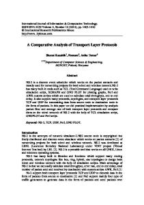
Task 1: Identify TCP Header Fields and Operation using a Wireshark FTP Session Capture. Step 1: Capture a FTP session. TCP sessions are well controlled and managed by information exchanged in the TCP header fields. In this task, a FTP session will be made to Eagle Server. When finished, the session capture will be analyzed. Windows computers use the FTP client, ftp, to connect to the FTP server. A command line window will start the FTP session, and the text configuration file for S1-central from Eagle Server will be downloaded, /pub/eagle_labs/eagle1/chapter4/s1-central, to the host computer. Open a command line window by clicking on Start | Run, type cmd, then press OK.
Figure 1. Command line window. A window similar to Figure 1 should open. Start a Wireshark capture on the interface that has IP address 172.16.Pod#.[1-2]. Start an FTP connection to Eagle Server. Type the command: > ftp eagle-server.example.com When prompted for a user id, type anonymous. When prompted for a password, press . Change the FTP directory to /pub/eagle_labs/eagle1/chapter4/: ftp> cd /pub/eagle_labs/eagle1/chapter4/ Download the file s1-central: ftp> get s1-central When finished, terminate the FTP sessions in each command line window with the FTP quit command: ftp> quit Close the command line window with the command exit: > exit Stop the Wireshark capture.
All contents are Copyright © 1992–2007 Cisco Systems, Inc. All rights reserved. This document is Cisco Public Information.
Page 3 of 10
CCNA Exploration Network Fundamentals: OSI Transport Layer
Lab 4.5.2: TCP/IP Transport Layer Protocols, TCP and UDP
Step 2: Analyze the TCP fields.
Figure 2. FTP capture. Switch to the Wireshark capture windows. The top window contains summary information for each captured record. Student capture should be similar to the capture shown in Figure 2. Before delving into TCP packet details, an explanation of the summary information is needed. When the FTP client is connected to the FTP server, the Transport Layer protocol TCP created a reliable session. TCP is routinely used during a session to control datagram delivery, verify datagram arrival, and manage window size. For each exchange of data between the FTP client and FTP server, a new TCP session is started. At the conclusion of the data transfer, the TCP session is closed. Finally, when the FTP session is finished TCP performs an orderly shutdown and termination.
Figure 3. Wireshark capture of a TCP datagram. In Wireshark, detailed TCP information is available in the middle window. Highlight the first TCP datagram from the host computer, and move the mouse pointer to the middle window. It may be necessary to adjust the middle window and expand the TCP record by clicking on the protocol expand box. The expanded TCP datagram should look similar to Figure 3.
All contents are Copyright © 1992–2007 Cisco Systems, Inc. All rights reserved. This document is Cisco Public Information.
Page 4 of 10
CCNA Exploration Network Fundamentals: OSI Transport Layer
Lab 4.5.2: TCP/IP Transport Layer Protocols, TCP and UDP
How is the first datagram in a TCP session identified? __________________________________________________________________________ __________________________________________________________________________
Figure 4. TCP packet fields. Refer to Figure 4, a TCP datagram diagram. An explanation of each field is provided to refresh the student’s memory: • •
• • •
• • •
TCP Source port number belongs to the TCP session host that opened a connection. The value is normally a random value above 1023. Destination port number is used to identify the upper layer protocol or application on the remote site. The values in the range 0–1023 represent the so called “well known ports” and are associated with popular services and applications (as described in RFC 1700, such as telnet, File Transfer Protocol (FTP), HyperText Transfer Protocol (HTTP), etc). The quadruple field combination (Source IP Address, Source Port, Destination IP Address, Destination Port) uniquely identifies the session to both sender and receiver. Sequence number specifies the number of the last octet in a segment. Acknowledgment number specifies the next octet expected by the receiver. Code Bits have a special meaning in session management and in the treatment of segments. Among interesting values are: • ACK (Acknowledgement of a segment receipt), • SYN (Synchronize, only set when a new TCP session is negotiated during the TCP threeway handshake). • FIN (Finish, request to close the TCP session). Window size is the value of the sliding window - how many octets can be sent before waiting for an acknowledgement. Urgent pointer is only used with an URG (Urgent) flag - when the sender needs to send urgent data to the receiver. Options: The only option currently defined is the maximum TCP segment size (optional value).
All contents are Copyright © 1992–2007 Cisco Systems, Inc. All rights reserved. This document is Cisco Public Information.
Page 5 of 10
CCNA Exploration Network Fundamentals: OSI Transport Layer
Lab 4.5.2: TCP/IP Transport Layer Protocols, TCP and UDP
Using the Wireshark capture of the first TCP session start-up (SYN bit set to 1), fill in information about the TCP header: From pod host computer to Eagle Server (only the SYN bit is set to 1): Source IP Address: 172.16.___.___ Destination IP Address: _______________ Source port number: ______________ Destination port number: ______________ Sequence number: ______________ Acknowledgement number: ___________ Header length: ______________ Window size: _______________ From Eagle Server to pod host computer (only SYN and ACK bits are set to 1): Source IP Address: ________________ Destination IP Address: 172.16.___.___ Source port number: ______________ Destination port number: ______________ Sequence number: ______________ Acknowledgement number: ___________ Header length: ______________ Window size: _______________ From pod host computer to Eagle Server (only ACK bit is set to 1): Source IP Address: 172.16.___.___ Destination IP Address: _______________ Source port number: ______________ Destination port number: ______________ Sequence number: ______________ Acknowledgement number: ___________ Header length: ______________ Window size: _______________ Ignoring the TCP session started when a data transfer occurred, how many other TCP datagrams contained a SYN bit? __________________________________________________________________________ __________________________________________________________________________ Attackers take advantage of the three-way handshake by initiating a “half-open” connection. In this sequence, the opening TCP session sends a TCP datagram with the SYN bit set and the receiver sends a related TCP datagram with the SYN ACK bits set. A final ACK bit is never sent to finish the TCP handshake. Instead, a new TCP connection is started in half-open fashion. With sufficient TCP sessions in the half-open state, the receiving computer may exhaust resources and crash. A crash could involve a loss of networking services, or corrupt the operating system. In either case the attacker has won, networking service has been stopped on the receiver. This is one example of a denial-of-service (DoS) attack.
All contents are Copyright © 1992–2007 Cisco Systems, Inc. All rights reserved. This document is Cisco Public Information.
Page 6 of 10
CCNA Exploration Network Fundamentals: OSI Transport Layer
Lab 4.5.2: TCP/IP Transport Layer Protocols, TCP and UDP
Figure 5. TCP session management. The FTP client and server communicate between each other, unaware and uncaring that TCP has control and management over the session. When the FTP server sends a Response: 220 to the FTP client, the TCP session on the FTP client sends an acknowledgment to the TCP session on Eagle Server. This sequence is shown in Figure 5, and is visible in the Wireshark capture.
Figure 6. Orderly TCP session termination. When the FTP session has finished, the FTP client sends a command to “quit”. The FTP server acknowledges the FTP termination with a Response :221 Goodbye. At this time the FTP server TCP session sends a TCP datagram to the FTP client, announcing the termination of the TCP session. The FTP client TCP session acknowledges receipt of the termination datagram, then sends its own TCP session termination. When the originator of the TCP termination, FTP server, receives a duplicate termination, an ACK datagram is sent to acknowledge the termination and the TCP session is closed. This sequence is shown in Figure 6, and visible in the Wireshark capture. Without an orderly termination, such as when the connection is broken, the TCP sessions will wait a certain period of time until closing. The default timeout value varies, but is normally 5 minutes.
Task 2: Identify UDP header fields and operation using a Wireshark TFTP session capture. Step 1: Capture a TFTP session. Following the procedure in Task 1 above, open a command line window. The TFTP command has a different syntax than FTP. For example, there is no authentication. Also, there are only two commands, get, to retrieve a file, and put, to send a file.
All contents are Copyright © 1992–2007 Cisco Systems, Inc. All rights reserved. This document is Cisco Public Information.
Page 7 of 10
CCNA Exploration Network Fundamentals: OSI Transport Layer
Lab 4.5.2: TCP/IP Transport Layer Protocols, TCP and UDP
>tftp –help Transfers files to and from a remote computer running the TFTP service. TFTP [-i] host [GET | PUT] source [destination] -i
host GET PUT source destination
Specifies binary image transfer mode (also called octet). In binary image mode the file is moved literally, byte by byte. Use this mode when transferring binary files. Specifies the local or remote host. Transfers the file destination on the remote host to the file source on the local host. Transfers the file source on the local host to the file destination on the remote host. Specifies the file to transfer. Specifies where to transfer the file. Table 1. TFTP syntax for a Windows TFTP client.
Table 1 contains Windows TFTP client syntax. The TFTP server has it’s own directory on Eagle Server, /tftpboot, which is different from the directory structure supported by the FTP server. No authentication is supported. Start a Wireshark capture, then download the s1-central configuration file from Eagle Server with the Windows TFTP client. The command and syntax to perform this is shown below: >tftp eagle-server.example.com get s1-central Step 2: Analyze the UDP fields.
Figure 7. Summary capture of a UDP session. Switch to the Wireshark capture windows. Student capture should be similar to the capture shown in Figure 7. A TFTP transfer will be used to analyze Transport Layer UDP operation.
All contents are Copyright © 1992–2007 Cisco Systems, Inc. All rights reserved. This document is Cisco Public Information.
Page 8 of 10
CCNA Exploration Network Fundamentals: OSI Transport Layer
Lab 4.5.2: TCP/IP Transport Layer Protocols, TCP and UDP
Figure 8. Wireshark capture of a UDP datagram. In Wireshark, detailed UDP information is available in the middle window. Highlight the first UDP datagram from the host computer, and move the mouse pointer to the middle window. It may be necessary to adjust the middle window and expand the UDP record by clicking on the protocol expand box. The expanded UDP datagram should look similar to Figure 8.
Figure 9. UDP format. Refer to Figure 9, a UDP datagram diagram. Header information is sparse, compared to the TCP datagram. There are similarities, however. Each UDP datagram is identified by the UDP source port and UDP destination port. Using the Wireshark capture of the first UDP datagram, fill in information about the UDP header. The checksum value is a hexadecimal (base 16) value, denoted by the preceding 0x code: Source IP Address: 172.16.___.___ Destination IP Address: _______________ Source port number: ______________ Destination port number: ______________ UDP message length: _____________ UDP checksum: _____________ How does UDP verify datagram integrity? __________________________________________________________________________ __________________________________________________________________________
All contents are Copyright © 1992–2007 Cisco Systems, Inc. All rights reserved. This document is Cisco Public Information.
Page 9 of 10
CCNA Exploration Network Fundamentals: OSI Transport Layer
Lab 4.5.2: TCP/IP Transport Layer Protocols, TCP and UDP
Examine the first packet returned from Eagle Server. Fill in information about the UDP header: Source IP Address: Destination IP Address: 172.16.___.___ Source port number: ______________ Destination port number: ______________ UDP message length: _____________ UDP checksum: 0x _____________ Notice that the return UDP datagram has a different UDP source port, but this source port is used for the remainder of the TFTP transfer. Since there is no reliable connection, only the original source port used to begin the TFTP session is used to maintain the TFTP transfer.
Task 5: Reflection. This lab provided students with the opportunity to analyze TCP and UDP protocol operations from captured FTP and TFTP sessions. TCP manages communication much differently from UDP, but reliability and guaranteed delivery requires additional control over the communication channel. UDP has less overhead and control, and the upper-layer protocol must provide some type of acknowledgement control. Both protocols, however, transport data between clients and servers using Application Layer protocols and are appropriate for the upper-layer protocol each supports.
Task 6: Challenge. Since neither FTP nor TFTP are secure protocols, all data transferred is sent in clear text. This includes any user ids, passwords, or clear text file contents. Analyzing the upper-layer FTP session will quickly identify the user id, password, and configuration file passwords. Upper-layer TFTP data examination is a bit more complicated, but the data field can be examined and configuration user id and password information extracted.
Task 7: Cleanup During this lab several files were transferred to the host computer, and should be removed. Unless directed otherwise by the instructor, turn off power to the host computers. Remove anything that was brought into the lab, and leave the room ready for the next class.
All contents are Copyright © 1992–2007 Cisco Systems, Inc. All rights reserved. This document is Cisco Public Information. Page 10 of 10